EP0262309B1 - Pneumatischer Messdorn - Google Patents
Pneumatischer Messdorn Download PDFInfo
- Publication number
- EP0262309B1 EP0262309B1 EP87109384A EP87109384A EP0262309B1 EP 0262309 B1 EP0262309 B1 EP 0262309B1 EP 87109384 A EP87109384 A EP 87109384A EP 87109384 A EP87109384 A EP 87109384A EP 0262309 B1 EP0262309 B1 EP 0262309B1
- Authority
- EP
- European Patent Office
- Prior art keywords
- measuring
- pins
- pin
- plug gauge
- bore
- Prior art date
- Legal status (The legal status is an assumption and is not a legal conclusion. Google has not performed a legal analysis and makes no representation as to the accuracy of the status listed.)
- Expired - Lifetime
Links
- 230000006835 compression Effects 0.000 description 1
- 238000007906 compression Methods 0.000 description 1
- 238000010276 construction Methods 0.000 description 1
- 238000005259 measurement Methods 0.000 description 1
Images
Classifications
-
- G—PHYSICS
- G01—MEASURING; TESTING
- G01B—MEASURING LENGTH, THICKNESS OR SIMILAR LINEAR DIMENSIONS; MEASURING ANGLES; MEASURING AREAS; MEASURING IRREGULARITIES OF SURFACES OR CONTOURS
- G01B13/00—Measuring arrangements characterised by the use of fluids
- G01B13/08—Measuring arrangements characterised by the use of fluids for measuring diameters
- G01B13/10—Measuring arrangements characterised by the use of fluids for measuring diameters internal diameters
Definitions
- the invention relates to a pneumatic measuring dome with at least two radially displaceable measuring pins, the outer ends of which act as a valve and come into contact with the inner wall of the recess to be measured, in particular the bore, in order to determine the flow rate of the measuring air in this position.
- Such a measuring dome is known from German Offenlegungsschrift 25 04 169.
- This known measuring dome allows tapered bores to be measured when the diameter of the bore becomes smaller from the outside inwards.
- the measuring dome is designed in a step-like manner.
- the object of the invention is to provide a measuring dome of the type mentioned at the outset, which permits measurement of ring grooves and recesses which have narrower diameters on the outside.
- This object is achieved in that each measuring pin forms the actuator of a separate valve, that each valve has a flow opening controlled by the measuring pin and that the measuring pins only reach the flow opening with their control edge in the extended state.
- the measuring pins of this measuring dome can be pneumatically extended far beyond the outer circumference of the measuring dome, in order then to reach a through-flow opening with an inner edge when in contact with the inner wall to be measured and thereby to control the flow rate of the measuring air exactly, so that the dimension can be specified exactly .
- the construction of the measuring dome is extremely simple, and a high degree of dimensional accuracy is achieved with optimum dirt resistance.
- a measuring air channel opens into the transverse bore receiving the measuring pins, the opening of which can be passed over by the inner end of the measuring pin in its extended position.
- a measuring air channel can open into the transverse bore receiving the measuring pins for each measuring pin, the opening of which can be passed over by a transverse bore in the measuring pin in its extended position.
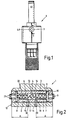
- the measuring dome 1 has a diametrical transverse bore 2, in which a tubular measuring cartridge 3 lies, the length and diameter of which approximately corresponds to the length and diameter of the transverse bore.
- a tubular measuring cartridge 3 in which a tubular measuring cartridge 3 lies, the length and diameter of which approximately corresponds to the length and diameter of the transverse bore.
- the central coaxial inner bore 4 of the cartridge 3 there are two radial pin-shaped measuring pins 5, 6, the outer diameter of which is only slightly smaller than the diameter of the inner bore 4 and which each have a coaxial blind bore 7, 8, each of which opens towards the inside, so that the outer ends of the measuring pins 5, 6 are closed and form curved contact surfaces 9 for the inner diameter to be measured.
- Both measuring pins 5, 6 are transversely penetrated by pins 10 which lie in longitudinal slots 11 of the measuring pin walls and are held in radial bores of the measuring cartridge.
- the length of the slots 11 determines the path by which the measuring pins can be moved outwards via the outer jacket 12 of the measuring mandrel 1.
- the distance A of the openings 15, 16 or the channels 17, 18 to the jacket 12 is thus less than the length of the measuring pins 5, 6, so that in the retracted state of the measuring pins, these completely close the openings 15, 16 with their outer jacket and in the extended position, the ends 14 partially cover the openings and thus form valves at these points, which indicate the exact position of the measuring pins 5, 6 in the measuring position and thus the exact diameter of the bore to be measured.
- the openings 15, 16 can be run over, in particular radial transverse bores of the measuring pins 5, 6 instead of through the inner end ends 14 and thereby determine the measuring air flowing out through the channels 17, 18.
- a spring 22 can lie in the bores 7, 8, which either presses the measuring pins 5, 6 additionally as a helical compression spring or pulls the measuring pins inwards as a tension spring, so that the pneumatic extension pressure must overcome this spring.
Landscapes
- Physics & Mathematics (AREA)
- General Physics & Mathematics (AREA)
- A Measuring Device Byusing Mechanical Method (AREA)
- Measuring Arrangements Characterized By The Use Of Fluids (AREA)
- Discharge Heating (AREA)
- Paper (AREA)
- Length Measuring Devices With Unspecified Measuring Means (AREA)
- Indication Of The Valve Opening Or Closing Status (AREA)
Description
- Die Erfindung betrifft einen pneumatischen Meßdom mit mindesten zwei radialen verschieblichen Meßstiften, deren äußere als Ventil wirkende Enden an der Innenwandung der zu messenden Ausnehmung, insbesondere der Bohrung zur Anlage gelangt, um in dieser Stellung die Durchflußmenge der Meßluft zu bestimmen.
- Ein solcher Meßdom ist aus der deutschen Offenlegungsschrift 25 04 169 bekannt. Dieser bekannte Meßdom läßt es zu, daß stufenförmig sich verjüngende Bohrungen gemessen werden, wenn die Durchmesser der Bohrung von außen nach innen geringer werden. In diesem Fall ist der Meßdom entsprechend stufenförmig gestaltet. Dagegen ist es nicht möglich, stufenförmige Erweiterungen zu messen, wenn äußere Bereiche der Bohrung einen geringeren Durchmesser aufweisen als innere. Damit sind Rücksprünge und Ringnuten nicht meßbar.
- Aufgabe der Erfindung ist es, einen Meßdom der eingangs genannten Art zu schaffen, der ein Messen von Ringnuten und Rücksprüngen erlaubt, die nach außen hin engere Durchmesser besitzen. Diese Aufgabe wird erfindungsgemäß dadurch gelöst, daß jeder Meßstift das Stellglied eines separaten Ventiles bildet, daß jedes Ventil eine vom Meßstift gesteuerte Durchströmöffnung aufweist und daß die Meßstifte mit ihrer Steuerkante die Durchströmöffnung erst im ausgefahrenen Zustand erreichen.
- Die Meßstifte dieses Meßdoms können weit über den Außenumfang des Meßdoms pneumatisch herausgefahren werden, um dann bei Anlage an der zu messenden Innenwandung mit einer inneren Kante eine Durchströmöffnung zu erreichen und hierdurch die Durchflußmenge der Meßluft exakt zu steuern, so daß das Maß exakt angegeben werden kann. Hierbei ist die Bauweise des Meßdoms äu- Berst einfach, und es wird eine hohe Maßgenauigkeit bei optimaler Schmutzunanfälligkeit erreicht.
- Besonders vorteilhaft ist es hierbei, wenn in der die Meßstifte aufnehmenden Querbohrung für jeden Meßstift ein Meßluftkanal mündet, dessen Mündungsöffnung vom inneren Ende des Meßstiftes in seiner ausgefahrenen Lage überfahrbar ist. Alternativ kann aber auch in der die Meßstifte aufnehmenden Querbohrung für jeden Meßstift ein Meßluftkanal münden, dessen Mündungsöffnung von einer Querbohrung im Meßstift in seiner ausgefahrenen Lage überfahrbar ist.
- Ein Ausführungsbeispiel der Erfindung ist in der Zeichnung dargestellt und wird im folgenden näher beschrieben. Es zeigen:
- Fig. 1 eine Seitenansicht des Meßdoms und
- FAig. 2 einen Schnitt nach 11-11 in Figur 1.
- Der Meßdom 1 weist eine diametrale Querbohrung 2 auf, in der eine rohrförmige Meßpatrone 3 einliegt, deren Länge und Durchmesser der Länge und Durchmesser der Querbohrung in etwa entspricht. In der mittigen koaxialen Innenbohrung 4 der Patrone 3 liegen zwei radiale bolzenförmige Meßstifte 5, 6 ein, deren Außendurchmesser nur wenig geringer ist als der Durchmesser der Innenbohrung 4 und die jeweils eine koaxiale Sackbohrung 7, 8 aufweisen, die jeweils zur Innenseite hin mündet, so daß die äußeren Enden der Meßstifte 5, 6 geschlossen sind und gewölbte Anlageflächen 9 für den zu messenden Innendurchmesser bilden.
- Beide Meßstifte 5, 6 sind von Stiften 10 quer durchdrungen, die in Längsschlitzen 11 der Meßstiftwandungen einliegen und in radialen Bohrungen der Meßpatrone gehalten sind. Die Länge der Schlitze 11 bestimmt den Weg, um den die Meßstifte nach außen über den Außenmantel 12 des Meßdorns 1 fahrbar sind.
- Um die beiden Meßstifte radial nach außen fahren zu können, wird über eine in die Innenbohrung 4 mittig mündende Leitung 13 Druckluft zwischen die Innenenden der Meßstifte 5, 6 eingegeben. Dieser pneumatische Druck wird so hoch gewählt, daß nach dem Einstecken des Meßdoms in die zu messende Bohrung die Meßstifte mit Sicherheit nach außen gegen die zu messende Wandung gedrückt werden. In dieser herausgefahrenen Meßstellung erreichen die hinteren Enden 14 der Meßstifte Öffnungen 15, 16 in der Innenwand der Bohrung 4, die von radialen Kanälen 17, 18 in der Meßpatrone gebildet werden. Diese Kanäle 17, 18 stehen in Verbindung mit Kanälen 19, 20 im Meßdom und führen zu Meßeinrichtungen, die den Druck in diesen Kanälen angeben. Hierbei wird nach der Bewegung der Meßstifte 5, 6 in ihren äußeren Stellungen meist ein geringerer Druck, d.h. der eigentliche Meßdruck verwendet.
- Der Abstand A der Öffnungen 15, 16 bzw. der Kanäle 17, 18 zum Mantel 12 ist damit geringer als die Länge der Meßstife 5, 6, so daß im eingefahrenen Zustand der Meßstifte diese die Öffnungen 15, 16 mit ihren Außenmäntein voll verschließen und in der herausgefahrenen Stellung die Enden 14 die Öffnungen teilweise überdecken und damit an diesen Stellen Ventile bilden, die die exakte Lage der Meßstifte 5, 6 in der Meßstellung und damit den genauen Durchmesser der zu messenden Bohrung angeben.
- Alternativ können die Öffnungen 15, 16 statt durch die inneren stirnseitigen Enden 14 auch durch seitliche Öffnung insbesondere radiale Querbohrungen der Meßstifte 5, 6 überfahren werden und hierbei die durch die Kanäle 17, 18 ausströmende Meßluft bestimmen.
- Seitlich der Anlageflächen 9 befinden sich in den äußeren Köpfen der Meßstifte 5, 6 seitliche Bohrungen 21, durch die ein Teil der Luft ausströmt um die zu messende Innenwandung sauber zu halten. Ferner kann eine Feder 22 in den Bohrungen 7, 8 einliegen, die entweder als Schraubendruckfeder die Meßstifte 5, 6 zusätzlich nach außen drückt oder aber die als Zugfeder die Meßstifte nach innen zieht, so daß der pneumatische Ausfahrdruck diese Feder überwinden muß.
Claims (4)
dadurch gekennzeichnet, daß in der die Meßstifte (5, 6) aufnehmenden Querbohrung (4) für jeden Meßstift ein Meßluftkanal (17, 18) mündet, dessen Mündungsöffnung (15, 16) vom inneren Ende (14) des Meßstiftes (5, 6) in seiner ausgefahrenen Lage überfahrbar ist.
dadurch gekennzeichnet, daß in der die Meßstifte (5, 6) aufnehmenden Querbohrung (4) für jeden Meßstift ein Meßluftkanal (17, 18) mündet, dessen Mündungsöffnung (15, 16) von einer Querbohrung im Meßstift (5, 6) in seiner ausgefahrenen Lage überfahrbar ist.
dadurch gekennzeichnet, daß beide Meßstifte (5, 6) in einer diametralen Patrone (3) koaxial verschieblich einliegen.
Priority Applications (1)
| Application Number | Priority Date | Filing Date | Title |
|---|---|---|---|
| AT87109384T ATE50056T1 (de) | 1986-10-03 | 1987-06-30 | Pneumatischer messdorn. |
Applications Claiming Priority (2)
| Application Number | Priority Date | Filing Date | Title |
|---|---|---|---|
| DE3633704 | 1986-10-03 | ||
| DE19863633704 DE3633704A1 (de) | 1986-10-03 | 1986-10-03 | Pneumatischer messdorn |
Publications (2)
| Publication Number | Publication Date |
|---|---|
| EP0262309A1 EP0262309A1 (de) | 1988-04-06 |
| EP0262309B1 true EP0262309B1 (de) | 1990-01-31 |
Family
ID=6310987
Family Applications (1)
| Application Number | Title | Priority Date | Filing Date |
|---|---|---|---|
| EP87109384A Expired - Lifetime EP0262309B1 (de) | 1986-10-03 | 1987-06-30 | Pneumatischer Messdorn |
Country Status (3)
| Country | Link |
|---|---|
| EP (1) | EP0262309B1 (de) |
| AT (1) | ATE50056T1 (de) |
| DE (2) | DE3633704A1 (de) |
Families Citing this family (3)
| Publication number | Priority date | Publication date | Assignee | Title |
|---|---|---|---|---|
| RU2275597C1 (ru) * | 2004-10-05 | 2006-04-27 | Закрытое акционерное общество "РС-Лизинг" | Устройство для контроля диаметра канавки в отверстии |
| RU2315950C1 (ru) * | 2006-07-07 | 2008-01-27 | Закрытое акционерное общество "РС-Лизинг" | Устройство для пневматического измерения отклонения от прямолинейности оси отверстия |
| CN108931175A (zh) * | 2018-09-17 | 2018-12-04 | 湖南联智桥隧技术有限公司 | 数显楔形塞尺、平整度试验方法及缝隙大小试验方法 |
Family Cites Families (7)
| Publication number | Priority date | Publication date | Assignee | Title |
|---|---|---|---|---|
| US2306469A (en) * | 1941-12-29 | 1942-12-29 | Gen Motors Corp | Air gauge |
| US2369319A (en) * | 1943-05-31 | 1945-02-13 | Gen Motors Corp | Gauge |
| US2775117A (en) * | 1952-10-15 | 1956-12-25 | Sheffield Corp | Pneumatic gauging device |
| US3102342A (en) * | 1960-06-02 | 1963-09-03 | Pratt & Whitney Co Inc | Precision gaging systems and apparatus |
| US3069899A (en) * | 1960-09-13 | 1962-12-25 | Gen Motors Corp | Pneumatic gauges for measuring bore diameters of workpieces |
| US3577642A (en) * | 1968-02-12 | 1971-05-04 | Joseph V Tripoli | In-process workpiece gaging apparatus |
| DE2504169A1 (de) * | 1975-02-01 | 1976-08-05 | Nieberding & Co Gmbh | Pneumatischer kontaktdorn |
-
1986
- 1986-10-03 DE DE19863633704 patent/DE3633704A1/de not_active Withdrawn
-
1987
- 1987-06-30 EP EP87109384A patent/EP0262309B1/de not_active Expired - Lifetime
- 1987-06-30 AT AT87109384T patent/ATE50056T1/de not_active IP Right Cessation
- 1987-06-30 DE DE8787109384T patent/DE3761596D1/de not_active Expired - Fee Related
Also Published As
| Publication number | Publication date |
|---|---|
| DE3633704A1 (de) | 1988-04-14 |
| EP0262309A1 (de) | 1988-04-06 |
| ATE50056T1 (de) | 1990-02-15 |
| DE3761596D1 (de) | 1990-03-08 |
Similar Documents
| Publication | Publication Date | Title |
|---|---|---|
| DE3211937C2 (de) | ||
| DE4000210C2 (de) | Kupplung für eine Kälteanlage | |
| DE69320951T2 (de) | Einstellbares ventil für pipettenpistole | |
| DE3814248C2 (de) | Einstellbares Drosselrückschlagventil | |
| DE1450598B1 (de) | Klappenventil | |
| DE69303778T2 (de) | Servogesteuertes Ventil | |
| DE2255278A1 (de) | Wasserhahn mit schieber | |
| EP0262309A1 (de) | Pneumatischer Messdorn | |
| DE3215696A1 (de) | Drosselrueckschlagventil | |
| DE1966571A1 (de) | Druckverminderer fuer wasser | |
| DE1450636C3 (de) | Rückschlagventil mit elastischer Sitzdichtung | |
| DE10064782C2 (de) | Hubventil | |
| DE1949198C3 (de) | Abdichtung und Drehsicherung einer in einer Gewindebohrung eines Gehäuses geführten, einstellbaren Drosselschraube | |
| DE3106507C2 (de) | Anschlußarmatur mit Absperrventil für Mengenzähler mit sogenanntem Einrohranschluß | |
| DE2601350C2 (de) | Druckminderventil | |
| DE2546442C2 (de) | Kupplung für Strömungsmittel-Leitungen | |
| DE1959446C3 (de) | Ventil zum Umwandeln von überhitztem Hochdruckdampf in Dampf niedrigeren Druckes und niedrigerer Temperatur | |
| DE2634721C2 (de) | Hydraulisches Drehschieberventil, insbesondere zum Wasseranschluß von Mund- oder Gesichtsreinigungsduschen | |
| DE1750620A1 (de) | Ventil | |
| DE2163758C2 (de) | Schnellkupplung zum Anschluß von Aparaturen an Leitungs-bzw. Behältersysteme mit unter Druck stehenden Fluiden | |
| DE1600813A1 (de) | Drosselventil | |
| DE851876C (de) | Loesbare Schlauch- oder Rohrkupplung | |
| DE659365C (de) | Durch ein Druckmittel, vorzugsweise Druckluft, beeinflusste, zum Staubsaugen oder fuer sonstige Zwecke verwendbare Saugeinrichtung | |
| DE2101006C3 (de) | Schlauchventil | |
| DE4312067A1 (de) | Ventil |
Legal Events
| Date | Code | Title | Description |
|---|---|---|---|
| PUAI | Public reference made under article 153(3) epc to a published international application that has entered the european phase |
Free format text: ORIGINAL CODE: 0009012 |
|
| AK | Designated contracting states |
Kind code of ref document: A1 Designated state(s): AT BE CH DE ES FR GB GR IT LI NL SE |
|
| 17P | Request for examination filed |
Effective date: 19880323 |
|
| 17Q | First examination report despatched |
Effective date: 19890712 |
|
| GRAA | (expected) grant |
Free format text: ORIGINAL CODE: 0009210 |
|
| AK | Designated contracting states |
Kind code of ref document: B1 Designated state(s): AT BE CH DE ES FR GB GR IT LI NL SE |
|
| PG25 | Lapsed in a contracting state [announced via postgrant information from national office to epo] |
Ref country code: IT Free format text: LAPSE BECAUSE OF FAILURE TO SUBMIT A TRANSLATION OF THE DESCRIPTION OR TO PAY THE FEE WITHIN THE PRE;WARNING: LAPSES OF ITALIAN PATENTS WITH EFFECTIVE DATE BEFORE 2007 MAY HAVE OCCURRED AT ANY TIME BEFORE 2007. THE CORRECT EFFECTIVE DATE MAY BE DIFFERENT FROM THE ONE RECORDED.SCRIBED TIME-LIMIT Effective date: 19900131 Ref country code: SE Effective date: 19900131 Ref country code: NL Effective date: 19900131 Ref country code: BE Effective date: 19900131 Ref country code: FR Effective date: 19900131 Ref country code: GR Free format text: LAPSE BECAUSE OF FAILURE TO SUBMIT A TRANSLATION OF THE DESCRIPTION OR TO PAY THE FEE WITHIN THE PRESCRIBED TIME-LIMIT Effective date: 19900131 Ref country code: GB Effective date: 19900131 |
|
| REF | Corresponds to: |
Ref document number: 50056 Country of ref document: AT Date of ref document: 19900215 Kind code of ref document: T |
|
| REF | Corresponds to: |
Ref document number: 3761596 Country of ref document: DE Date of ref document: 19900308 |
|
| PG25 | Lapsed in a contracting state [announced via postgrant information from national office to epo] |
Ref country code: ES Free format text: LAPSE BECAUSE OF FAILURE TO SUBMIT A TRANSLATION OF THE DESCRIPTION OR TO PAY THE FEE WITHIN THE PRESCRIBED TIME-LIMIT Effective date: 19900512 |
|
| EN | Fr: translation not filed | ||
| NLV1 | Nl: lapsed or annulled due to failure to fulfill the requirements of art. 29p and 29m of the patents act | ||
| GBV | Gb: ep patent (uk) treated as always having been void in accordance with gb section 77(7)/1977 [no translation filed] | ||
| PLBE | No opposition filed within time limit |
Free format text: ORIGINAL CODE: 0009261 |
|
| STAA | Information on the status of an ep patent application or granted ep patent |
Free format text: STATUS: NO OPPOSITION FILED WITHIN TIME LIMIT |
|
| 26N | No opposition filed | ||
| PGFP | Annual fee paid to national office [announced via postgrant information from national office to epo] |
Ref country code: CH Payment date: 19930526 Year of fee payment: 7 |
|
| PGFP | Annual fee paid to national office [announced via postgrant information from national office to epo] |
Ref country code: AT Payment date: 19930601 Year of fee payment: 7 |
|
| PGFP | Annual fee paid to national office [announced via postgrant information from national office to epo] |
Ref country code: DE Payment date: 19930729 Year of fee payment: 7 |
|
| PG25 | Lapsed in a contracting state [announced via postgrant information from national office to epo] |
Ref country code: CH Effective date: 19940630 Ref country code: LI Effective date: 19940630 Ref country code: AT Effective date: 19940630 |
|
| REG | Reference to a national code |
Ref country code: CH Ref legal event code: PL |
|
| PG25 | Lapsed in a contracting state [announced via postgrant information from national office to epo] |
Ref country code: DE Effective date: 19950301 |