EP0262363A2 - Procédé et dispositif pour la fabrication en continu de corps tubulaires à l'aide d'une soudure de joint longitudinal par laser - Google Patents
Procédé et dispositif pour la fabrication en continu de corps tubulaires à l'aide d'une soudure de joint longitudinal par laser Download PDFInfo
- Publication number
- EP0262363A2 EP0262363A2 EP87111872A EP87111872A EP0262363A2 EP 0262363 A2 EP0262363 A2 EP 0262363A2 EP 87111872 A EP87111872 A EP 87111872A EP 87111872 A EP87111872 A EP 87111872A EP 0262363 A2 EP0262363 A2 EP 0262363A2
- Authority
- EP
- European Patent Office
- Prior art keywords
- welding
- laser beam
- compression
- designed
- strip
- Prior art date
- Legal status (The legal status is an assumption and is not a legal conclusion. Google has not performed a legal analysis and makes no representation as to the accuracy of the status listed.)
- Granted
Links
Images



Classifications
-
- C—CHEMISTRY; METALLURGY
- C21—METALLURGY OF IRON
- C21D—MODIFYING THE PHYSICAL STRUCTURE OF FERROUS METALS; GENERAL DEVICES FOR HEAT TREATMENT OF FERROUS OR NON-FERROUS METALS OR ALLOYS; MAKING METAL MALLEABLE, e.g. BY DECARBURISATION OR TEMPERING
- C21D9/00—Heat treatment, e.g. annealing, hardening, quenching or tempering, adapted for particular articles; Furnaces therefor
- C21D9/50—Heat treatment, e.g. annealing, hardening, quenching or tempering, adapted for particular articles; Furnaces therefor for welded joints
- C21D9/505—Cooling thereof
-
- B—PERFORMING OPERATIONS; TRANSPORTING
- B21—MECHANICAL METAL-WORKING WITHOUT ESSENTIALLY REMOVING MATERIAL; PUNCHING METAL
- B21C—MANUFACTURE OF METAL SHEETS, WIRE, RODS, TUBES, PROFILES OR LIKE SEMI-MANUFACTURED PRODUCTS OTHERWISE THAN BY ROLLING; AUXILIARY OPERATIONS USED IN CONNECTION WITH METAL-WORKING WITHOUT ESSENTIALLY REMOVING MATERIAL
- B21C37/00—Manufacture of metal sheets, rods, wire, tubes, profiles or like semi-manufactured products, not otherwise provided for; Manufacture of tubes of special shape
- B21C37/06—Manufacture of metal sheets, rods, wire, tubes, profiles or like semi-manufactured products, not otherwise provided for; Manufacture of tubes of special shape of tubes or metal hoses; Combined procedures for making tubes, e.g. for making multi-wall tubes
- B21C37/08—Making tubes with welded or soldered seams
-
- B—PERFORMING OPERATIONS; TRANSPORTING
- B23—MACHINE TOOLS; METAL-WORKING NOT OTHERWISE PROVIDED FOR
- B23K—SOLDERING OR UNSOLDERING; WELDING; CLADDING OR PLATING BY SOLDERING OR WELDING; CUTTING BY APPLYING HEAT LOCALLY, e.g. FLAME CUTTING; WORKING BY LASER BEAM
- B23K26/00—Working by laser beam, e.g. welding, cutting or boring
- B23K26/02—Positioning or observing the workpiece, e.g. with respect to the point of impact; Aligning, aiming or focusing the laser beam
- B23K26/03—Observing, e.g. monitoring, the workpiece
- B23K26/032—Observing, e.g. monitoring, the workpiece using optical means
-
- B—PERFORMING OPERATIONS; TRANSPORTING
- B23—MACHINE TOOLS; METAL-WORKING NOT OTHERWISE PROVIDED FOR
- B23K—SOLDERING OR UNSOLDERING; WELDING; CLADDING OR PLATING BY SOLDERING OR WELDING; CUTTING BY APPLYING HEAT LOCALLY, e.g. FLAME CUTTING; WORKING BY LASER BEAM
- B23K26/00—Working by laser beam, e.g. welding, cutting or boring
- B23K26/02—Positioning or observing the workpiece, e.g. with respect to the point of impact; Aligning, aiming or focusing the laser beam
- B23K26/03—Observing, e.g. monitoring, the workpiece
- B23K26/034—Observing the temperature of the workpiece
-
- B—PERFORMING OPERATIONS; TRANSPORTING
- B23—MACHINE TOOLS; METAL-WORKING NOT OTHERWISE PROVIDED FOR
- B23K—SOLDERING OR UNSOLDERING; WELDING; CLADDING OR PLATING BY SOLDERING OR WELDING; CUTTING BY APPLYING HEAT LOCALLY, e.g. FLAME CUTTING; WORKING BY LASER BEAM
- B23K26/00—Working by laser beam, e.g. welding, cutting or boring
- B23K26/02—Positioning or observing the workpiece, e.g. with respect to the point of impact; Aligning, aiming or focusing the laser beam
- B23K26/04—Automatically aligning, aiming or focusing the laser beam, e.g. using the back-scattered light
- B23K26/044—Seam tracking
-
- B—PERFORMING OPERATIONS; TRANSPORTING
- B23—MACHINE TOOLS; METAL-WORKING NOT OTHERWISE PROVIDED FOR
- B23K—SOLDERING OR UNSOLDERING; WELDING; CLADDING OR PLATING BY SOLDERING OR WELDING; CUTTING BY APPLYING HEAT LOCALLY, e.g. FLAME CUTTING; WORKING BY LASER BEAM
- B23K26/00—Working by laser beam, e.g. welding, cutting or boring
- B23K26/20—Bonding
- B23K26/21—Bonding by welding
- B23K26/24—Seam welding
- B23K26/26—Seam welding of rectilinear seams
- B23K26/262—Seam welding of rectilinear seams of longitudinal seams of tubes
-
- B—PERFORMING OPERATIONS; TRANSPORTING
- B23—MACHINE TOOLS; METAL-WORKING NOT OTHERWISE PROVIDED FOR
- B23K—SOLDERING OR UNSOLDERING; WELDING; CLADDING OR PLATING BY SOLDERING OR WELDING; CUTTING BY APPLYING HEAT LOCALLY, e.g. FLAME CUTTING; WORKING BY LASER BEAM
- B23K26/00—Working by laser beam, e.g. welding, cutting or boring
- B23K26/60—Preliminary treatment
-
- B—PERFORMING OPERATIONS; TRANSPORTING
- B23—MACHINE TOOLS; METAL-WORKING NOT OTHERWISE PROVIDED FOR
- B23K—SOLDERING OR UNSOLDERING; WELDING; CLADDING OR PLATING BY SOLDERING OR WELDING; CUTTING BY APPLYING HEAT LOCALLY, e.g. FLAME CUTTING; WORKING BY LASER BEAM
- B23K2101/00—Articles made by soldering, welding or cutting
- B23K2101/007—Marks, e.g. trade marks
-
- B—PERFORMING OPERATIONS; TRANSPORTING
- B23—MACHINE TOOLS; METAL-WORKING NOT OTHERWISE PROVIDED FOR
- B23K—SOLDERING OR UNSOLDERING; WELDING; CLADDING OR PLATING BY SOLDERING OR WELDING; CUTTING BY APPLYING HEAT LOCALLY, e.g. FLAME CUTTING; WORKING BY LASER BEAM
- B23K2103/00—Materials to be soldered, welded or cut
- B23K2103/02—Iron or ferrous alloys
- B23K2103/04—Steel or steel alloys
-
- B—PERFORMING OPERATIONS; TRANSPORTING
- B23—MACHINE TOOLS; METAL-WORKING NOT OTHERWISE PROVIDED FOR
- B23K—SOLDERING OR UNSOLDERING; WELDING; CLADDING OR PLATING BY SOLDERING OR WELDING; CUTTING BY APPLYING HEAT LOCALLY, e.g. FLAME CUTTING; WORKING BY LASER BEAM
- B23K2103/00—Materials to be soldered, welded or cut
- B23K2103/02—Iron or ferrous alloys
- B23K2103/04—Steel or steel alloys
- B23K2103/05—Stainless steel
-
- F—MECHANICAL ENGINEERING; LIGHTING; HEATING; WEAPONS; BLASTING
- F28—HEAT EXCHANGE IN GENERAL
- F28F—DETAILS OF HEAT-EXCHANGE AND HEAT-TRANSFER APPARATUS, OF GENERAL APPLICATION
- F28F2275/00—Fastening; Joining
- F28F2275/06—Fastening; Joining by welding
- F28F2275/067—Fastening; Joining by welding by laser welding
Definitions
- the invention relates to a method for producing tubular bodies, in which coated or uncoated steel strip is continuously formed into a slotted tube and the opposite strip edges are longitudinally welded at high speed by a laser beam of high energy density with or without the addition of additional material under protective gas.
- the method for welding the butt surfaces of sheet metal which is shown in DE-33 04 717 A1, includes compression or deformation of the melt and thus the butt surfaces during the welding process.
- This also in pipe production - e.g. B. in inductive welding processes - known as "pressure welding" allows a qualitatively not so complex strip edge preparation, since the part of the melt or strip edge surfaces, which may contain irregularities or imperfections, is pressed out of the seam area and in the form of a bulge on the The inner and outer surface of the seam cooled.
- the melt can only be pressed in the liquid or doughy state depending on the path and not on the force, since the liquid melting phase of the material does not permit measurable compression force transmission. This can be seen in the uncontrolled formation of the bulge on both sides of the seam.
- the invention is therefore based on the object of specifying a method which makes the industrial manufacture of laser-welded metal pipes possible even with increasing wall thicknesses and higher speeds and thereby provides a seam with structural, geometric and material properties designed such that the entire seam area is in all properties necessary for the intended use after manufacture correspond to those of the base material.
- the invention makes available a device that is suitable for carrying out the generic method.
- the disclosed method offers the The advantage that a defined, predictable and controllable seam formation takes place through a swaging of the weld seam following the actual welding and the subsequent controlled cooling.
- Such a process in which the strip edges are advantageously melt-welded perpendicular to the strip edge surface while maintaining a small welding gap without pressure and compressed after defined cooling, eliminates the seam relapse that occurs during fusion welding on both sides of the seam on the inner and outer surface in the transition area to the base material.
- a welding bead which develops in a random and completely uncontrolled manner in terms of shape and volume, on the inside and outside of the seam, as occurs when the principle of pressure welding is applied, i.e. the compression of the melt at the welding point, in which a compressive force is exerted by the extremely low compressive strength of the liquid metal phase cannot be absorbed.
- the deep welding with the help of the laser beam takes place with the formation of a heat cylinder (keyhole) which surrounds the laser beam in the material acted upon by the focus area and consists of two phases, namely the molten material and the vaporized, electrical charge-bearing material, the plasma.
- a heat cylinder keyhole
- the claimed method also realizes the control of the compression path and / or the compression force as a function of the compression bead after the compression has been carried out, since the foreseeable, uniform, always approximately circular segment-shaped configuration of the compression bead on the inside as well as on the outside also allows an assessment of the volume only a measured geometric size of the respective welding bead can take place.
- the claimed device is able to carry out reliable laser welding with good seam geometry and high production speed even for pipes with large wall thickness / diameter ratio by providing all the necessary actuators, shaping devices, observation systems and controls.
- the welding takes place under protective gas, since this advantageously influences the plasma formation and reactions of the material with the atmospheric oxygen can be avoided.
- Special alloys which undergo a change due to the heating of the strip edges to the melting temperature and are to be returned to their original state - also in the area of the weld seam - require the addition of additional material.
- inductive recording devices are often more practical in place of the complex optical recording devices.
- the only geometrical size to be measured, depending on the tube size and recording device, is advantageously the height, the width or the flank angle of the compression bead.
- the simplest alternative for relatively large pipe diameters is to measure the height of the compression bead using mechanical buttons or inductive sensors.
- an optical width measurement is useful, while in the case of small stainless steel tubes, especially if they are to be examined for the formation of the inner bulge, an optical flank angle measurement with measuring light striking the bulge is appropriate.
- the control of the upsetting is realized by actuating the actuators of the respective upsetting devices, whereby advantageously a processing device which compares electrical impulses proportional to the respective geometrical sizes of the upsetting beads and assigns them to a defined volume ratio for a given dimension and gives a control impulse to the delivery members of the upsetting devices.
- the cooling between fusion welding and upsetting advantageously takes place in the case of carbon steels up to a maximum of a temperature corresponding to the stop Ar 3 of the iron-carbon diagram; for stainless steels and austenitic steels up to a maximum temperature corresponding to the solidification and dendrite formation.
- the melt is sufficiently strong and therefore capable of transferring compressive forces, but at the same time it prevents the freezing of tensions or the build-up of microstructures in the seam areas that favor cold work hardening.
- a radiation pyrometer which generates an electrical pulse proportional to the temperature of the seam area, is advantageously used as the temperature device.
- a processing device can provide control pulses for a heating device in the simplest way.
- heat radiators which - as is known to be operated with electricity or gas - can be installed above the seam area.
- the best initial seam geometry of the fusion weld seam is achieved when both strip edges in the laser focus area are exposed to a radiation of approximately the same intensity.
- this distance is usually between 0.04 mm and 0.25 mm.
- This guidance is realized in a simple manner in that the focus point of the laser beam is adapted to the band edges with the aid of a level position control, whereby - The depth coordinate coincides with the optical axis of the focused laser beam - And the transverse coordinate is formed perpendicular to the pipe axis and as an arc segment, the center of which lies in the pipe axis and the radius of which is determined by the distance of the focus point from the pipe axis.
- a control with such coordinates is e.g. B. enabled by a three-coordinate control, the welding gap deviation in the circumferential direction as an input variable for positioning the focus point in the transverse coordinate determined by a non-contact seam tracking system and converted into proportional electrical pulses.
- An optically operating system offers the advantage that a measurement is extremely precise and independent of the outside diameter and, if the deviation in the circumferential direction of a marking parallel to the strip edge is determined, even a measurement synchronous to the welding point is possible.
- the distance of the pipe surface at the band edges relative to the focus point parallel to the optical axis of the focused laser beam can be converted into proportional electrical pulses and used as an input variable for controlling the depth coordinate by measuring the distance.
- a laser measuring device works here with particular precision, which also offers the advantage that the measurement can be carried out in close proximity to the welding point and that a partial beam coupled out of the welding beam can also be used for the measurement.
- a processing unit generates control pulses for the three-coordinate control in a simple manner while working up the electrical pulses of the seam tracking system and the distance measuring system.
- the strip edges are conveniently brought together so closely in the laser welding for the coupling of sufficiently large energy that their distance, ie the gap width, is smaller than the diameter of the focus point. This is done in a simple manner either by guide elements rolling on the tube circumference, in particular in the longitudinal direction of the tube, in the known form of roller rulers or cages, and by guide rollers.
- guide elements which slide on the tube circumference, in particular in the longitudinal direction of the tube, which consist of slide guides for the band edges and / or form funnels and stones, are useful.
- the necessary guide elements at least in the height axis parallel to the offset direction, the edge offset existing between these guide elements and the welding point first being determined by a measuring device and converted into proportional electrical pulses.
- An advantage here is a light section measuring device which, in addition to a fast measuring frequency, also enables the strip edge offset to be interpreted in the correct direction.
- a processing device In combination with position sensors which convert the respective position of the guide elements for guiding the strip edges in the offset direction into proportional electrical pulses, a processing device easily creates the control pulses for these guide elements.
- Appropriate position sensors are advantageously designed as potentiometers.
- the processing device converts the electrical impulses of the welding gap width measurement into control signals for the guide elements which bring the strip edge surfaces towards one another.
- a precise fusion welding is advantageously achieved by a strip edge preparation which leads to an average roughness depth of the strip edge surfaces which is less than half of a beam diameter adjacent to the focus diameter of the laser beam at the welding point.
- This beam diameter depends on the degree of focus of the laser beam, which in turn is set as a function of the wall thickness.
- the preparation of the strip edges is done in a simple manner by machining, that is to say by planing, grinding or milling the strip edge surfaces by means of a strip edge preparation unit equipped with appropriate tools in one work step or in several machining steps which successively refine the surface of the strip edge.
- a band edge preparation can be implemented with little effort by upsetting deformation perpendicular to the band edge surfaces with the aid of an appropriate upsetting device.
- this is advantageously carried out by integrated cutter disc structures.
- the preparation of the strip edges by the laser cutting process which is characterized by particularly low mean roughness depths of the cut surfaces, is also advantageous.
- a partial beam can also be coupled out of this and used to cut the strip edges.
- the schematic diagram (Fig. 1) shows a laser beam 1, which is focused using a lens 2 and has a power density between 0.5 x 10⁶ W / cm2 and 5 x 10⁷ W / cm2 in the welding spot. This enables deep welding of the strip edges 4 and 5 to form a heat cylinder 3 (keyhole) surrounding the laser beam in the material.
- the gap width 6 of the welding gap 7 is smaller than the focus diameter 8 of the laser beam 1 at the welding point 9.
- the drop-shaped weld pool 10 melts at its front edge 11 the strip edges 4 and 5 arriving in the feed direction 12.
- the melt 13 (hatched) solidifies in a rear edge zone 14 of the weld pool 10.
- the further solidifying weld seam 15 then passes through the cooling section 16 to the compression point 17 and the compression represented by the force arrows 18.
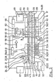
- Fig. 2 shows the schematic representation of a laser welding device for performing the generic method explained by the schematic diagram 1.
- a contactless seam tracking system 20 consists in a known manner of a light source 22 illuminating the slotted tube surface 21 obliquely to the feed direction 12 of a television camera 23 positioned above the welding gap 7, which takes a high-contrast video image based on the light beams 24 reflected by the tube surface 21 or absorbed in the welding gap 7 from the evaluation unit 25.
- a commercial television camera is sufficient here, which shows a binary image as a field transverse to the tube axis 26 of e.g. B. 512 x 256 pixels without shades of gray.
- the evaluation unit 25 processes the amplitudes of the incoming video signals in a known manner with the aid of a threshold which corresponds to an average brightness value and which detects the distinction between reflection and absorption of the light beams 24 with sufficient precision.
- the shift in the contrast limit ie the limit between the reflecting and absorbing surface of the workpiece, is made available for further processing after an electronic determination of the center of gravity of the contrast difference by an analog voltage Ug proportional to the welding gap deviation in the circumferential direction.
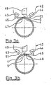
- Each of the band edges 4 and 5 is guided from the outside by roller rulers 27 and 28 (FIG. 3c) with the aid of the rollers 29 - 34 calibrated to the tube circumference.
- the roller rulers 27 and 28 are vertically adjustable perpendicular to the tube axis 26 and receive their supporting force from the supporting roller ruler 35 with the prism rollers 36, 37 and 38.
- the dimension of the set height of the roller rulers 27 and 28 is determined via the respective potentiometers 39 and 40 (FIG. 2) and supplied to the processing unit 41 as a proportional analog voltage Ur.
- the light section measuring device 42 detects the offset of the strip edges 4 and 5 and the welding gap width 6 in front of the welding point 9.
- 3a and 3b show in principle the operation of the light section measuring device 42 with the two lighting elements 43 and 44 positioned to the left and right of the welding gap 7, which alternately with a frequency of greater than or equal to 3 Hz, the welding gap 7 obliquely to the strip edges 4 and 5 and perpendicular to Illuminate the pipe axis.
- the shaded areas 47 and 48 are formed, which are detected by the diode line camera 49 on the basis of the differently reflected light beams 50 and 51.
- the welding gap also provides a shadow or absorption area corresponding to its width.
- the diode line camera 49 equipped with a resolution of up to 3000 pixels per line, converts the length of the shadow areas 47 and 48, which is proportional to the height of the band edge offset 45 and 46, into an analog voltage Ub, which is fed to the processing unit 41.
- a voltage US proportional to the width of the welding gap is fed to the processing unit 41 from the camera 49.
- the processing unit 41 After processing and comparison with the voltage Ur proportional to the height position of the roller rulers 27 and 28, the processing unit 41 generates a control voltage which is fed to the servomotors (not shown here) for the height adjustment of the roller rulers 27 and 28.
- FIG. 2 shows the induction coil 52, which is operated via the medium-frequency generator 53, in the further course of the production device.
- the performance of the medium frequency generator 53 is controlled by a processing device 54 which receives an analog voltage Ut proportional to this temperature from the radiation pyrometer 55, which measures the seam temperature behind the compression point 17 and thus determines the preheating of the strip edges 4 and 5, and into a control voltage formed for the medium frequency generator 53.
- the welding guide rollers 56 and 57 guide the slotted tube 19 at the welding point 9 without, however, exerting pressure on the band edges 4 and 5 perpendicular to the band edge surface (FIG. 4 a) and while maintaining a 0.3 mm wide welding gap 6.
- the infeed of the welding guide rollers 56 and 57 of the processing device 41 is controlled after the proportional tension US has been worked up.
- a measuring laser 58 measures the distance, parallel to the optical axis of the focused laser beam, of the slot tube surface at the strip edges 4 and 5 relative to the welding point 9.
- the distance measurement is carried out using the known triangulation method in which a laser beam is applied obliquely to the Surface of an object is directed, reflected and received again.
- the distance between the starting point of the measuring beam and the receiving point of the reflected beam which is directly proportional to the distance to the surface of the object and is given to the processing unit 59 in the form of an analog voltage U1 as an input signal, is evaluated with the aid of a line camera.
- the processing unit 59 supplies the control voltages from the evaluation unit 25 for the electrical drives (not shown here) of the three-coordinate control 60 of the laser welding head 61.
- the laser welding head 61 has a protective gas supply 62, via which the protective gas is guided to the welding point 9 through an annular space (not shown) surrounding the laser beam in the laser welding head 61.
- the fusion-welded seam 63 passes through the cooling section 16 at the feed rate up to the compression point 17, where it is compressed by the compression rollers 64 and 65 perpendicular to the direction of the weld thickness (FIG. 4b).
- the upsetting rollers 64 and 65 are supplied by servomotors, not shown here, which act on adjusting spindles and which receive their control voltages via the processing device 66.
- the processing device 66 evaluates and compares the analog voltages received as output signals from the television camera units 67 and 68.
- the commercial endoscopes 69 and 70 each have a circular optical fiber package for viewing and a surrounding, circular optical fiber package for illuminating the area to be imaged.
- the strip edge preparation unit 71 shows the strip edge preparation unit 71, in which the strip material 72, which has not yet been formed, is guided through holding rollers 73 and 74 and is processed on both strip edges 4 and 5 by hydraulically operated planing tools 75 and 76.
- the band edges 4 and 5 are slightly beveled at an angle which compensates for the warping of the band edges which occurs due to the tensile and compressive stresses in the outer and inner fibers after the shaping.
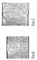
- Fig. 6 shows a cross section of the melt-welded seam 63 of a tube of the dimension DA 63.5 x Wd 5 mm in a corresponding enlargement.
- Ferritic stainless steel was used as the material. The seam relapses on the inside and outside on the left and right of the seam at the transition to the base material are clearly visible.
- the described method for larger wall thicknesses can of course also be used for small wall thicknesses below 3 mm.
Landscapes
- Engineering & Computer Science (AREA)
- Physics & Mathematics (AREA)
- Optics & Photonics (AREA)
- Mechanical Engineering (AREA)
- Plasma & Fusion (AREA)
- Chemical & Material Sciences (AREA)
- Thermal Sciences (AREA)
- Crystallography & Structural Chemistry (AREA)
- Materials Engineering (AREA)
- Metallurgy (AREA)
- Organic Chemistry (AREA)
- Laser Beam Processing (AREA)
Priority Applications (1)
| Application Number | Priority Date | Filing Date | Title |
|---|---|---|---|
| AT87111872T ATE46287T1 (de) | 1986-09-27 | 1987-08-17 | Verfahren und vorrichtung zur kontinuierlichen herstellung rohrfoermiger koerper mittels laserl|ngsnahtschweissung. |
Applications Claiming Priority (2)
| Application Number | Priority Date | Filing Date | Title |
|---|---|---|---|
| DE19863632952 DE3632952A1 (de) | 1986-09-27 | 1986-09-27 | Verfahren und vorrichtung zur kontinuierlichen herstellung rohrfoermiger koerper mittels laser-laengsnahtschweissung |
| DE3632952 | 1986-09-27 |
Publications (3)
| Publication Number | Publication Date |
|---|---|
| EP0262363A2 true EP0262363A2 (fr) | 1988-04-06 |
| EP0262363A3 EP0262363A3 (en) | 1988-09-28 |
| EP0262363B1 EP0262363B1 (fr) | 1989-09-13 |
Family
ID=6310540
Family Applications (1)
| Application Number | Title | Priority Date | Filing Date |
|---|---|---|---|
| EP87111872A Expired EP0262363B1 (fr) | 1986-09-27 | 1987-08-17 | Procédé et dispositif pour la fabrication en continu de corps tubulaires à l'aide d'une soudure de joint longitudinal par laser |
Country Status (12)
| Country | Link |
|---|---|
| US (1) | US4827099A (fr) |
| EP (1) | EP0262363B1 (fr) |
| JP (1) | JPS6390383A (fr) |
| AR (1) | AR243106A1 (fr) |
| AT (1) | ATE46287T1 (fr) |
| BR (1) | BR8704959A (fr) |
| CA (1) | CA1288824C (fr) |
| DE (2) | DE3632952A1 (fr) |
| ES (1) | ES2002093B3 (fr) |
| GR (2) | GR880300082T1 (fr) |
| MX (1) | MX171291B (fr) |
| SU (1) | SU1718714A3 (fr) |
Cited By (15)
| Publication number | Priority date | Publication date | Assignee | Title |
|---|---|---|---|---|
| FR2660225A1 (fr) * | 1990-03-28 | 1991-10-04 | Alcatel Nv | Procede et appareil de soudage longitudinal des bords d'un tube metallique de faible diametre. |
| FR2690095A1 (fr) * | 1992-04-17 | 1993-10-22 | Kertscher Sa E | Procédé de fabrication d'une enveloppe tubulaire métallique et enveloppe obtenue selon ce procédé. |
| EP0688878A1 (fr) * | 1994-06-23 | 1995-12-27 | Elpatronic Ag | Procédé et dispositif pour le post-traitement de tÔles soudées |
| EP0823295A1 (fr) * | 1996-08-08 | 1998-02-11 | Hewing GmbH | Procédé pour revêtir un tube en matière synthétiquer avec une bande métallique et poste de soudage pour souder les bords se chevauchant de la bande métallique |
| RU2139159C1 (ru) * | 1994-09-24 | 1999-10-10 | Алькатель Кабель АГ унд Ко. | Способ изготовления металлической трубки со сварным продольным швом |
| WO2008014740A1 (fr) * | 2006-08-01 | 2008-02-07 | Eroform Edelstahl Gmbh | Suspension pour un appareil de soudure laser |
| EP2062674A1 (fr) * | 2007-11-20 | 2009-05-27 | Trumpf Werkzeugmaschinen GmbH + Co. KG | Procédé de préparation et de réalisation d'un processus de soudure laser |
| DE102012204207A1 (de) | 2012-03-16 | 2013-09-19 | Trumpf Werkzeugmaschinen Gmbh + Co. Kg | Verfahren zum Laserstrahlschweißen |
| FR2989295A1 (fr) * | 2012-04-16 | 2013-10-18 | Air Liquide | Procede de fabrication de fil fourre par soudage laser avec preparation prealable des bords du feuillard |
| EP1818581B1 (fr) * | 2006-02-10 | 2014-08-13 | Carl Freudenberg KG | Méthode de fabrication pour un anneau d'étanchéité |
| EP2322312A4 (fr) * | 2008-06-23 | 2015-05-27 | Jfe Steel Corp | Procédé de fabrication d'un tuyau d'acier soudé au laser |
| CN104668783A (zh) * | 2015-02-06 | 2015-06-03 | 武汉华工激光工程有限责任公司 | 人字形筛缝管激光加工工艺 |
| CN109523548A (zh) * | 2018-12-21 | 2019-03-26 | 哈尔滨工业大学 | 一种基于临界阈值的窄间隙焊缝特征点提取方法 |
| DE102019205461A1 (de) * | 2019-04-16 | 2020-10-22 | BSH Hausgeräte GmbH | Verfahren zum Herstellen eines Hohlzylinder ähnlicher Körpers einer Trommel eines Haushaltsgeräts sowie für ein Haushaltsgerät |
| EP4060272B1 (fr) | 2021-03-19 | 2023-08-02 | Steinmüller Engineering GmbH | Paroi de tube/membrane contenant des tubes à soudure longitudinale |
Families Citing this family (59)
| Publication number | Priority date | Publication date | Assignee | Title |
|---|---|---|---|---|
| DE3842865A1 (de) * | 1987-12-24 | 1989-07-06 | Franz Anton Schroeder | Verfahren zur herstellung eines laengsnahtrohres |
| US5045668A (en) † | 1990-04-12 | 1991-09-03 | Armco Inc. | Apparatus and method for automatically aligning a welding device for butt welding workpieces |
| RU2150362C1 (ru) * | 1992-04-12 | 2000-06-10 | Эльпатроник АГ | Способ и устройство для сварки листов в сварную листовую заготовку посредством лазера |
| DE4339661C2 (de) * | 1993-11-22 | 1996-09-26 | Fraunhofer Ges Forschung | Verfahren zum Herstellen von röhrenförmigen Rohlingen aus Fein- oder Feinstblech |
| JPH0847716A (ja) * | 1994-08-05 | 1996-02-20 | Nkk Corp | 耐hicおよび耐sscc特性に優れた電縫鋼管の製造方法 |
| JP3233542B2 (ja) * | 1995-02-14 | 2001-11-26 | 株式会社オーシーシー | 金属管被覆光ファイバケーブルの製造方法及び製造装置 |
| DE19515853C2 (de) * | 1995-04-29 | 2001-01-18 | Hewing Gmbh | Verfahren zum Ummanteln eines Kunststoffrohres mit einer Metallummantelung |
| US5961748A (en) * | 1995-08-09 | 1999-10-05 | Nkk Corporation | Laser-welded steel pipe |
| DE59608130D1 (de) * | 1995-10-06 | 2001-12-13 | Elpatronic Ag Bergdietikon | Verfahren zum Kontrollieren und Positionieren eines Strahls zum Bearbeiten von Werkstücken |
| DE19545713C2 (de) * | 1995-12-07 | 1999-05-12 | Thyssen Stahl Ag | Verfahren und Vorrichtung zum Stumpfschweißen zweier Bleche oder Bänder |
| JP3767047B2 (ja) | 1996-04-26 | 2006-04-19 | セイコーエプソン株式会社 | 投写型表示装置 |
| RU2120365C1 (ru) * | 1996-12-10 | 1998-10-20 | Юрий Степанович Комиссарчук | Способ изготовления продольношовных труб сваркой лазером и устройство для его осуществления |
| GB9626065D0 (en) * | 1996-12-16 | 1997-02-05 | Metal Box Plc | Measurement of welds |
| USRE38194E1 (en) * | 1996-12-18 | 2003-07-22 | Seiko Epson Corporation | Projection display device |
| DE19758001C2 (de) * | 1997-04-30 | 2001-08-30 | Rohrwerke Muldenstein Gmbh | Verfahren und Gerätesystem zur schweißtechnischen Fertigung von Großrohren |
| JP3743145B2 (ja) * | 1997-12-01 | 2006-02-08 | セイコーエプソン株式会社 | 投写型表示装置 |
| DE10042538A1 (de) * | 2000-08-30 | 2002-03-14 | Volkswagen Ag | Verfahren zum Laserschweißen mit definierter Spaltweite |
| US6913056B2 (en) * | 2002-01-31 | 2005-07-05 | Baxter International Inc. | Apparatus and method for connecting and disconnecting flexible tubing |
| MY137246A (en) * | 2002-04-30 | 2009-01-30 | Jfe Steel Corp | Method and instrument for measuring bead cutting shape of electric welded tube |
| US7275543B2 (en) | 2002-09-20 | 2007-10-02 | Baxter International Inc. | Coupler member for joining dissimilar materials |
| FI117426B (fi) * | 2003-06-12 | 2006-10-13 | Aker Yards Oy | Menetelmä kolmidimensionaalisen rakenteen hitsauksen ohjaamiseksi |
| US7722733B2 (en) * | 2004-03-29 | 2010-05-25 | Baxter International Inc. | Method for sterile connection of tubing |
| KR100489692B1 (ko) * | 2004-06-16 | 2005-05-17 | 엘에스전선 주식회사 | 플라즈마와 레이저를 이용한 연속적인 맞대기 용접방법 및이를 이용한 금속관 제조방법 |
| GB0419059D0 (en) * | 2004-08-26 | 2004-09-29 | Ici Plc | Sediment assessment |
| US7094988B1 (en) * | 2005-04-18 | 2006-08-22 | Honeywell International, Inc. | Laser welding heat treat process |
| DE102007030395B4 (de) | 2007-06-29 | 2010-09-30 | Trumpf Werkzeugmaschinen Gmbh + Co. Kg | Verfahren und Vorrichtung zum Laserstrahlschweißen eines Werkstücks |
| DE502007002627D1 (de) * | 2007-08-01 | 2010-03-04 | Freudenberg Carl Kg | Verfahren zur Herstellung eines Dichtrings |
| FR2923295B1 (fr) * | 2007-11-06 | 2009-12-11 | Areva Np | Procede et dispositif de visualisation et de controle du profil d'un cordon de soudure a l'interieur d'un chanfrein menage entre deux pieces metalliques |
| KR101257360B1 (ko) * | 2008-03-31 | 2013-04-23 | 제이에프이 스틸 가부시키가이샤 | 고밀도 에너지 빔으로 접합한 용접 강관 및 그의 제조 방법 |
| DE102008032509A1 (de) * | 2008-07-10 | 2010-01-14 | Epcos Ag | Heizungsvorrichtung und Verfahren zur Herstellung der Heizungsvorrichtung |
| DE102009020146B3 (de) * | 2009-04-08 | 2010-06-10 | V & M Deutschland Gmbh | Verfahren und Vorrichtung zum Verbinden der Enden von Rohren aus Stahl mittels Orbitalschweißen in Hybridtechnik |
| JP5523045B2 (ja) * | 2009-10-02 | 2014-06-18 | 日立造船株式会社 | コイルの製造装置及び製造方法 |
| DE102009050784B4 (de) * | 2009-10-27 | 2012-02-16 | Lessmüller Lasertechnik GmbH | Verfahren zur bildgestützten Kontrolle von Bearbeitungsprozessen und Verfahren zur Reparatur von Defekten an Werkstücken |
| DE102010063113A1 (de) * | 2010-12-15 | 2012-06-21 | Endress + Hauser Gmbh + Co. Kg | Werkstück |
| WO2012147213A1 (fr) * | 2011-04-28 | 2012-11-01 | Jfeスチール株式会社 | Procédé pour la production de tuyau en acier soudé au laser |
| CN102327921A (zh) * | 2011-06-10 | 2012-01-25 | 苏州九方焊割科技有限公司 | 一种预焊机的主压轮机构 |
| US20130119040A1 (en) * | 2011-11-11 | 2013-05-16 | Lincoln Global, Inc. | System and method for adaptive fill welding using image capture |
| RU2488457C1 (ru) * | 2012-01-17 | 2013-07-27 | Открытое акционерное общество "Электростальский завод тяжелого машиностроения" | Устройство для формовки и сварки продольных швов труб |
| RU2633123C2 (ru) * | 2013-05-20 | 2017-10-11 | ДжФЕ СТИЛ КОРПОРЕЙШН | Контроллер коррекции смещения и способ управления коррекцией смещения в агрегате непрерывной сварки прихваточным швом |
| CN105246613B (zh) * | 2013-05-24 | 2017-03-08 | 杰富意钢铁株式会社 | 钢管的制造方法 |
| JP5967042B2 (ja) * | 2013-09-12 | 2016-08-10 | Jfeスチール株式会社 | レーザ溶接良否判定装置及びレーザ溶接良否判定方法 |
| US10166635B2 (en) | 2013-09-17 | 2019-01-01 | Stiwa Holding Gmbh | Welding device comprising an active heating device for heating the workpiece |
| JP6262166B2 (ja) * | 2014-03-31 | 2018-01-17 | Jfeスチール株式会社 | ベンディングプレス成形用金型 |
| JP6015997B1 (ja) * | 2014-11-25 | 2016-10-26 | Jfeスチール株式会社 | 鋼管の製造方法及びその方法に使用するプレス金型 |
| DE102016103571A1 (de) * | 2016-02-29 | 2017-08-31 | Oetiker Schweiz Ag | Verfahren zum Herstellen eine geschweißten Rings |
| AU2017304971B2 (en) | 2016-07-27 | 2019-05-16 | Dai-Ichi High Frequency Co., Ltd. | Post-heat treatment device and post-heat treatment method |
| CN110177629B (zh) | 2017-01-16 | 2021-05-14 | 车里阿宾斯克轧管装置公共联合股份公司 | 用于生产管道的装焊机 |
| RU2637038C1 (ru) * | 2017-01-30 | 2017-11-29 | Публичное акционерное общество "Челябинский трубопрокатный завод" (ПАО "ЧТПЗ") | Способ сварки труб методом лазерной сварки |
| CN111093887B (zh) * | 2018-02-16 | 2022-06-28 | 松下知识产权经营株式会社 | 激光焊接装置及激光焊接方法 |
| WO2019198443A1 (fr) * | 2018-04-13 | 2019-10-17 | パナソニックIpマネジメント株式会社 | Dispositif de soudage au laser |
| JP6791397B2 (ja) * | 2018-09-14 | 2020-11-25 | Jfeスチール株式会社 | 鋼管の製造方法及びプレス金型 |
| EP3685954B1 (fr) * | 2019-01-22 | 2024-01-24 | Synova S.A. | Procédé de découpe de pièce à l'aide d'un faisceau laser complex guidé par jet de fluide |
| RU2723493C1 (ru) * | 2019-07-15 | 2020-06-11 | федеральное государственное бюджетное образовательное учреждение высшего образования "Пермский национальный исследовательский политехнический университет" | Способ лазерной сварки с контролем процесса формирования сварного шва |
| EP3797891B1 (fr) * | 2019-09-30 | 2023-08-02 | Nexans | Procédé de fabrication en continu de profilés creux, ondulés par sections, minces, de petit diamètre en metal non ferreux |
| CN111889878A (zh) * | 2020-08-13 | 2020-11-06 | 隋国刚 | 一种薄板激光焊接装置及其焊接操作方法 |
| DE102020215088A1 (de) | 2020-12-01 | 2022-06-02 | Sms Group Gmbh | Verfahren zur Herstellung von Schlitzrohren |
| DE102021109787A1 (de) * | 2021-04-19 | 2022-10-20 | Precitec Gmbh & Co. Kg | Verfahren zum Vergleichen von Laserbearbeitungssystemen und Verfahren zum Überwachen eines Laserbearbeitungsprozesses sowie dazugehöriges Laserbearbeitungssystem |
| JP7713186B2 (ja) * | 2021-08-18 | 2025-07-25 | エンシュウ株式会社 | レーザ加工装置 |
| CN116689963B (zh) * | 2023-06-25 | 2023-12-01 | 浙江摩多巴克斯科技股份有限公司 | 一种高强度钢管的激光焊接工艺 |
Family Cites Families (7)
| Publication number | Priority date | Publication date | Assignee | Title |
|---|---|---|---|---|
| FR2338766A1 (fr) * | 1976-01-20 | 1977-08-19 | Saurin Emmanuel | Procede de fabrication d'une boite de conserve et dispositif pour l'execution de ce procede |
| US4341943A (en) * | 1979-10-23 | 1982-07-27 | Sws Incorporated | Method of butt welding sheet metal |
| US4436979A (en) * | 1982-05-06 | 1984-03-13 | Sws, Incorporated | Apparatus for continuous laser welding |
| DE3304717A1 (de) * | 1983-02-11 | 1984-08-16 | BIAS Forschungs- und Entwicklungs-Labor für angewandte Strahltechnik GmbH, 2820 Bremen | Verfahren und vorrichtung zum schweissen plastisch verformbarer werkstoffe |
| US4577088A (en) * | 1984-06-27 | 1986-03-18 | Sws Inc. | Method of laser butt welding |
| DE3502368A1 (de) * | 1985-01-25 | 1986-07-31 | Thyssen Stahl AG, 4100 Duisburg | Verfahren zum stumpfschweissen von mindestens einseitig verzinkten, insbesondere tiefziehfaehigen stahlblechen oder stahlbaender |
| JPS6316887A (ja) * | 1986-07-07 | 1988-01-23 | Toyo Seikan Kaisha Ltd | 溶接缶胴体 |
-
1986
- 1986-09-27 DE DE19863632952 patent/DE3632952A1/de active Granted
-
1987
- 1987-08-17 ES ES87111872T patent/ES2002093B3/es not_active Expired - Lifetime
- 1987-08-17 AT AT87111872T patent/ATE46287T1/de not_active IP Right Cessation
- 1987-08-17 DE DE8787111872T patent/DE3760548D1/de not_active Expired
- 1987-08-17 EP EP87111872A patent/EP0262363B1/fr not_active Expired
- 1987-09-10 AR AR87308677A patent/AR243106A1/es active
- 1987-09-18 US US07/098,280 patent/US4827099A/en not_active Expired - Fee Related
- 1987-09-25 BR BR8704959A patent/BR8704959A/pt not_active Application Discontinuation
- 1987-09-25 SU SU874203352A patent/SU1718714A3/ru active
- 1987-09-25 MX MX008532A patent/MX171291B/es unknown
- 1987-09-28 JP JP62241030A patent/JPS6390383A/ja active Pending
- 1987-09-28 CA CA000548541A patent/CA1288824C/fr not_active Expired - Fee Related
-
1988
- 1988-10-21 GR GR88300082T patent/GR880300082T1/el unknown
-
1989
- 1989-12-12 GR GR89400294T patent/GR3000250T3/el unknown
Cited By (19)
| Publication number | Priority date | Publication date | Assignee | Title |
|---|---|---|---|---|
| FR2660225A1 (fr) * | 1990-03-28 | 1991-10-04 | Alcatel Nv | Procede et appareil de soudage longitudinal des bords d'un tube metallique de faible diametre. |
| FR2690095A1 (fr) * | 1992-04-17 | 1993-10-22 | Kertscher Sa E | Procédé de fabrication d'une enveloppe tubulaire métallique et enveloppe obtenue selon ce procédé. |
| EP0688878A1 (fr) * | 1994-06-23 | 1995-12-27 | Elpatronic Ag | Procédé et dispositif pour le post-traitement de tÔles soudées |
| US5639012A (en) * | 1994-06-23 | 1997-06-17 | Elpatronic Ag | Process and device for the posttreatment of welded compound panels |
| RU2139159C1 (ru) * | 1994-09-24 | 1999-10-10 | Алькатель Кабель АГ унд Ко. | Способ изготовления металлической трубки со сварным продольным швом |
| EP0823295A1 (fr) * | 1996-08-08 | 1998-02-11 | Hewing GmbH | Procédé pour revêtir un tube en matière synthétiquer avec une bande métallique et poste de soudage pour souder les bords se chevauchant de la bande métallique |
| EP1818581B1 (fr) * | 2006-02-10 | 2014-08-13 | Carl Freudenberg KG | Méthode de fabrication pour un anneau d'étanchéité |
| WO2008014740A1 (fr) * | 2006-08-01 | 2008-02-07 | Eroform Edelstahl Gmbh | Suspension pour un appareil de soudure laser |
| EP2062674A1 (fr) * | 2007-11-20 | 2009-05-27 | Trumpf Werkzeugmaschinen GmbH + Co. KG | Procédé de préparation et de réalisation d'un processus de soudure laser |
| EP2322312A4 (fr) * | 2008-06-23 | 2015-05-27 | Jfe Steel Corp | Procédé de fabrication d'un tuyau d'acier soudé au laser |
| DE102012204207A1 (de) | 2012-03-16 | 2013-09-19 | Trumpf Werkzeugmaschinen Gmbh + Co. Kg | Verfahren zum Laserstrahlschweißen |
| DE102012204207B4 (de) * | 2012-03-16 | 2015-02-19 | Trumpf Werkzeugmaschinen Gmbh + Co. Kg | Verfahren zum Laserstrahlschweißen |
| EP2653260A1 (fr) * | 2012-04-16 | 2013-10-23 | L'air Liquide, Societe Anonyme Pour L'etude Et L'exploitation Des Procedes Georges Claude | Procédé de fabrication de fil fourré par soudage laser avec préparation préalable des bords du feuillard |
| FR2989295A1 (fr) * | 2012-04-16 | 2013-10-18 | Air Liquide | Procede de fabrication de fil fourre par soudage laser avec preparation prealable des bords du feuillard |
| CN104668783A (zh) * | 2015-02-06 | 2015-06-03 | 武汉华工激光工程有限责任公司 | 人字形筛缝管激光加工工艺 |
| CN109523548A (zh) * | 2018-12-21 | 2019-03-26 | 哈尔滨工业大学 | 一种基于临界阈值的窄间隙焊缝特征点提取方法 |
| CN109523548B (zh) * | 2018-12-21 | 2023-05-05 | 哈尔滨工业大学 | 一种基于临界阈值的窄间隙焊缝特征点提取方法 |
| DE102019205461A1 (de) * | 2019-04-16 | 2020-10-22 | BSH Hausgeräte GmbH | Verfahren zum Herstellen eines Hohlzylinder ähnlicher Körpers einer Trommel eines Haushaltsgeräts sowie für ein Haushaltsgerät |
| EP4060272B1 (fr) | 2021-03-19 | 2023-08-02 | Steinmüller Engineering GmbH | Paroi de tube/membrane contenant des tubes à soudure longitudinale |
Also Published As
| Publication number | Publication date |
|---|---|
| EP0262363B1 (fr) | 1989-09-13 |
| CA1288824C (fr) | 1991-09-10 |
| SU1718714A3 (ru) | 1992-03-07 |
| ES2002093A4 (es) | 1988-07-16 |
| AR243106A1 (es) | 1993-07-30 |
| DE3632952A1 (de) | 1988-04-07 |
| DE3760548D1 (en) | 1989-10-19 |
| US4827099A (en) | 1989-05-02 |
| GR880300082T1 (en) | 1988-10-21 |
| JPS6390383A (ja) | 1988-04-21 |
| GR3000250T3 (en) | 1991-03-15 |
| MX171291B (es) | 1993-10-18 |
| DE3632952C2 (fr) | 1988-08-25 |
| BR8704959A (pt) | 1988-05-17 |
| EP0262363A3 (en) | 1988-09-28 |
| ES2002093B3 (es) | 1990-01-01 |
| ATE46287T1 (de) | 1989-09-15 |
Similar Documents
| Publication | Publication Date | Title |
|---|---|---|
| EP0262363B1 (fr) | Procédé et dispositif pour la fabrication en continu de corps tubulaires à l'aide d'une soudure de joint longitudinal par laser | |
| EP2310163B1 (fr) | Procédé d'orientation excentrée d'un faisceau laser par rapport à un axe de buse et de découpage oblique, tête d'usinage laser et machine d'usinage laser correspondantes | |
| EP0313594B1 (fr) | Dispositif et procede d'assemblage par rayonnement laser | |
| DE69127121T2 (de) | Vorrichtung und Verfahren zum automatischen Ausrichten einer Schweissvorrichtung zum Stumpfschweissen von Werkstücken | |
| DE102007038502B4 (de) | Verfahren zum Fügen von mindestens zwei Werkstücken mittels eines Laserstrahls | |
| DE102010018686B4 (de) | Vorrichtung und Verfahren zum Laser-Auftragschweißen mit pulverförmigem Zusatzwerkstoff | |
| WO2018059901A1 (fr) | Procédé et machine d'usinage laser destinés au soudage laser d'une première et d'une deuxième sections d'une pièce à usiner | |
| DE102014203025A1 (de) | Verfahren zum Laserstrahlschweißen und Schweißkopf | |
| DE10126871C1 (de) | Verfahren und Vorrichtung zum robotergesteuerten Schneiden von zu fügenden Werkstücken mit Laserstrahlung | |
| DE102011001710A1 (de) | Verfahren und Vorrichtung zur Laserstrahlbearbeitung eines Werkstücks | |
| DE102014015094A1 (de) | Verfahren zum Laserstrahlschweißen | |
| DE102013008085B4 (de) | Verfahren und Vorrichtung zum Fügen von Werkstücken mit einem Bearbeitungsstrahl | |
| DE102005004787A1 (de) | Laserschweißnaht mit verkleinertem Endkrater und Verfahren zu deren Herstellung | |
| DE8900556U1 (de) | Vorrichtung zum Spannen und anschließenden Verbinden von Blechen mittels Laser-Naht-Schweißen im Karosseriebau | |
| EP3186031B1 (fr) | Procédé de saignage dans des pièces métalliques au moyen d'un faisceau laser ainsi que machine d'usinage à laser et produit de programme informatique associés | |
| WO2008077537A1 (fr) | Dispositif de dressage à la flamme | |
| WO2006024465A1 (fr) | Procede et dispositif d'usinage au laser de surfaces interieures cylindriques comprenant un systeme de balayage par faisceau commandable | |
| EP4031319B1 (fr) | Dispositif d'alimentation en matière | |
| DE10355051B4 (de) | Verfahren und Vorrichtung zum Laserstrahlschweißen mit verringerter Abzeichnung | |
| DE19758001C2 (de) | Verfahren und Gerätesystem zur schweißtechnischen Fertigung von Großrohren | |
| DE102015115183A1 (de) | Verfahren und eine Vorrichtung zum Herstellen einer Fügeverbindung | |
| DE2552401B2 (de) | Verfahren und Vorrichtung zur kontinuierlichen Wärmebehandlung geschweißter Rohre mit verstärkter Schweißnaht | |
| DE19635843C2 (de) | Rohrschweißanlage zur Herstellung eines geschweißten Rundrohres aus einem flachen Materialband | |
| DE102008054040A1 (de) | Verfahren zur Herstellung von Blechverbindungen durch Nahtschweißen | |
| EP1629931B1 (fr) | Procédé et dispositif de soudage laser pour assembler des tôles métalliques avec un jeu entre les tôles controllé par un capteur mesurant le plasma généré par le laser |
Legal Events
| Date | Code | Title | Description |
|---|---|---|---|
| PUAI | Public reference made under article 153(3) epc to a published international application that has entered the european phase |
Free format text: ORIGINAL CODE: 0009012 |
|
| AK | Designated contracting states |
Kind code of ref document: A2 Designated state(s): AT BE CH DE ES FR GB GR IT LI LU NL SE |
|
| ITCL | It: translation for ep claims filed |
Representative=s name: RICCARDI SERGIO & CO. |
|
| TCNL | Nl: translation of patent claims filed | ||
| GBC | Gb: translation of claims filed (gb section 78(7)/1977) | ||
| EL | Fr: translation of claims filed | ||
| PUAL | Search report despatched |
Free format text: ORIGINAL CODE: 0009013 |
|
| AK | Designated contracting states |
Kind code of ref document: A3 Designated state(s): AT BE CH DE ES FR GB GR IT LI LU NL SE |
|
| 17P | Request for examination filed |
Effective date: 19880916 |
|
| 17Q | First examination report despatched |
Effective date: 19890215 |
|
| GRAA | (expected) grant |
Free format text: ORIGINAL CODE: 0009210 |
|
| AK | Designated contracting states |
Kind code of ref document: B1 Designated state(s): AT BE CH DE ES FR GB GR IT LI LU NL SE |
|
| REF | Corresponds to: |
Ref document number: 46287 Country of ref document: AT Date of ref document: 19890915 Kind code of ref document: T |
|
| GBT | Gb: translation of ep patent filed (gb section 77(6)(a)/1977) | ||
| REF | Corresponds to: |
Ref document number: 3760548 Country of ref document: DE Date of ref document: 19891019 |
|
| ET | Fr: translation filed | ||
| ITF | It: translation for a ep patent filed | ||
| PLBE | No opposition filed within time limit |
Free format text: ORIGINAL CODE: 0009261 |
|
| STAA | Information on the status of an ep patent application or granted ep patent |
Free format text: STATUS: NO OPPOSITION FILED WITHIN TIME LIMIT |
|
| REG | Reference to a national code |
Ref country code: GR Ref legal event code: FG4A Free format text: 3000250 |
|
| 26N | No opposition filed | ||
| ITTA | It: last paid annual fee | ||
| PGFP | Annual fee paid to national office [announced via postgrant information from national office to epo] |
Ref country code: GB Payment date: 19930714 Year of fee payment: 7 Ref country code: CH Payment date: 19930714 Year of fee payment: 7 |
|
| PGFP | Annual fee paid to national office [announced via postgrant information from national office to epo] |
Ref country code: LU Payment date: 19930719 Year of fee payment: 7 |
|
| PGFP | Annual fee paid to national office [announced via postgrant information from national office to epo] |
Ref country code: FR Payment date: 19930720 Year of fee payment: 7 Ref country code: AT Payment date: 19930720 Year of fee payment: 7 |
|
| PGFP | Annual fee paid to national office [announced via postgrant information from national office to epo] |
Ref country code: SE Payment date: 19930723 Year of fee payment: 7 |
|
| PGFP | Annual fee paid to national office [announced via postgrant information from national office to epo] |
Ref country code: GR Payment date: 19930727 Year of fee payment: 7 |
|
| PGFP | Annual fee paid to national office [announced via postgrant information from national office to epo] |
Ref country code: ES Payment date: 19930730 Year of fee payment: 7 |
|
| PGFP | Annual fee paid to national office [announced via postgrant information from national office to epo] |
Ref country code: NL Payment date: 19930831 Year of fee payment: 7 |
|
| PGFP | Annual fee paid to national office [announced via postgrant information from national office to epo] |
Ref country code: BE Payment date: 19930903 Year of fee payment: 7 |
|
| PGFP | Annual fee paid to national office [announced via postgrant information from national office to epo] |
Ref country code: DE Payment date: 19930924 Year of fee payment: 7 |
|
| EPTA | Lu: last paid annual fee | ||
| PG25 | Lapsed in a contracting state [announced via postgrant information from national office to epo] |
Ref country code: LU Free format text: LAPSE BECAUSE OF NON-PAYMENT OF DUE FEES Effective date: 19940817 Ref country code: GB Effective date: 19940817 Ref country code: AT Effective date: 19940817 |
|
| PG25 | Lapsed in a contracting state [announced via postgrant information from national office to epo] |
Ref country code: SE Effective date: 19940818 Ref country code: ES Free format text: LAPSE BECAUSE OF EXPIRATION OF PROTECTION Effective date: 19940818 |
|
| PG25 | Lapsed in a contracting state [announced via postgrant information from national office to epo] |
Ref country code: LI Effective date: 19940831 Ref country code: CH Effective date: 19940831 Ref country code: BE Effective date: 19940831 |
|
| EAL | Se: european patent in force in sweden |
Ref document number: 87111872.5 |
|
| BERE | Be: lapsed |
Owner name: HOESCH A.G. Effective date: 19940831 |
|
| PG25 | Lapsed in a contracting state [announced via postgrant information from national office to epo] |
Ref country code: GR Free format text: THE PATENT HAS BEEN ANNULLED BY A DECISION OF A NATIONAL AUTHORITY Effective date: 19950228 |
|
| PG25 | Lapsed in a contracting state [announced via postgrant information from national office to epo] |
Ref country code: NL Effective date: 19950301 |
|
| NLV4 | Nl: lapsed or anulled due to non-payment of the annual fee | ||
| GBPC | Gb: european patent ceased through non-payment of renewal fee |
Effective date: 19940817 |
|
| PG25 | Lapsed in a contracting state [announced via postgrant information from national office to epo] |
Ref country code: FR Effective date: 19950428 |
|
| REG | Reference to a national code |
Ref country code: CH Ref legal event code: PL Ref country code: GR Ref legal event code: MM2A Free format text: 3000250 |
|
| PG25 | Lapsed in a contracting state [announced via postgrant information from national office to epo] |
Ref country code: DE Effective date: 19950503 |
|
| EUG | Se: european patent has lapsed |
Ref document number: 87111872.5 |
|
| REG | Reference to a national code |
Ref country code: FR Ref legal event code: ST |
|
| REG | Reference to a national code |
Ref country code: ES Ref legal event code: FD2A Effective date: 19990601 |
|
| PG25 | Lapsed in a contracting state [announced via postgrant information from national office to epo] |
Ref country code: IT Free format text: LAPSE BECAUSE OF NON-PAYMENT OF DUE FEES;WARNING: LAPSES OF ITALIAN PATENTS WITH EFFECTIVE DATE BEFORE 2007 MAY HAVE OCCURRED AT ANY TIME BEFORE 2007. THE CORRECT EFFECTIVE DATE MAY BE DIFFERENT FROM THE ONE RECORDED. Effective date: 20050817 |