EP0262438A2 - Lasersender mit einem Halbleiterlaser und einem externen optischen Resonator in Form eines frequenzselektiven Faserrichtkopplers - Google Patents
Lasersender mit einem Halbleiterlaser und einem externen optischen Resonator in Form eines frequenzselektiven Faserrichtkopplers Download PDFInfo
- Publication number
- EP0262438A2 EP0262438A2 EP87112825A EP87112825A EP0262438A2 EP 0262438 A2 EP0262438 A2 EP 0262438A2 EP 87112825 A EP87112825 A EP 87112825A EP 87112825 A EP87112825 A EP 87112825A EP 0262438 A2 EP0262438 A2 EP 0262438A2
- Authority
- EP
- European Patent Office
- Prior art keywords
- waveguide
- transmitter
- semiconductor laser
- rke
- feedback device
- Prior art date
- Legal status (The legal status is an assumption and is not a legal conclusion. Google has not performed a legal analysis and makes no representation as to the accuracy of the status listed.)
- Granted
Links
- 239000000835 fiber Substances 0.000 title claims abstract description 45
- 239000004065 semiconductor Substances 0.000 title claims abstract description 17
- 230000005855 radiation Effects 0.000 claims abstract description 18
- 230000003287 optical effect Effects 0.000 claims abstract description 12
- 230000008878 coupling Effects 0.000 claims description 19
- 238000010168 coupling process Methods 0.000 claims description 19
- 238000005859 coupling reaction Methods 0.000 claims description 19
- 239000004020 conductor Substances 0.000 description 1
- 230000007423 decrease Effects 0.000 description 1
- 230000003071 parasitic effect Effects 0.000 description 1
- 230000035945 sensitivity Effects 0.000 description 1
- 238000001228 spectrum Methods 0.000 description 1
Images
Classifications
-
- H—ELECTRICITY
- H01—ELECTRIC ELEMENTS
- H01S—DEVICES USING THE PROCESS OF LIGHT AMPLIFICATION BY STIMULATED EMISSION OF RADIATION [LASER] TO AMPLIFY OR GENERATE LIGHT; DEVICES USING STIMULATED EMISSION OF ELECTROMAGNETIC RADIATION IN WAVE RANGES OTHER THAN OPTICAL
- H01S5/00—Semiconductor lasers
- H01S5/10—Construction or shape of the optical resonator, e.g. extended or external cavity, coupled cavities, bent-guide, varying width, thickness or composition of the active region
- H01S5/14—External cavity lasers
- H01S5/146—External cavity lasers using a fiber as external cavity
-
- G—PHYSICS
- G02—OPTICS
- G02B—OPTICAL ELEMENTS, SYSTEMS OR APPARATUS
- G02B6/00—Light guides; Structural details of arrangements comprising light guides and other optical elements, e.g. couplings
- G02B6/24—Coupling light guides
- G02B6/26—Optical coupling means
- G02B6/262—Optical details of coupling light into, or out of, or between fibre ends, e.g. special fibre end shapes or associated optical elements
-
- G—PHYSICS
- G02—OPTICS
- G02B—OPTICAL ELEMENTS, SYSTEMS OR APPARATUS
- G02B6/00—Light guides; Structural details of arrangements comprising light guides and other optical elements, e.g. couplings
- G02B6/24—Coupling light guides
- G02B6/26—Optical coupling means
- G02B6/28—Optical coupling means having data bus means, i.e. plural waveguides interconnected and providing an inherently bidirectional system by mixing and splitting signals
- G02B6/2804—Optical coupling means having data bus means, i.e. plural waveguides interconnected and providing an inherently bidirectional system by mixing and splitting signals forming multipart couplers without wavelength selective elements, e.g. "T" couplers, star couplers
- G02B6/2821—Optical coupling means having data bus means, i.e. plural waveguides interconnected and providing an inherently bidirectional system by mixing and splitting signals forming multipart couplers without wavelength selective elements, e.g. "T" couplers, star couplers using lateral coupling between contiguous fibres to split or combine optical signals
-
- G—PHYSICS
- G02—OPTICS
- G02B—OPTICAL ELEMENTS, SYSTEMS OR APPARATUS
- G02B6/00—Light guides; Structural details of arrangements comprising light guides and other optical elements, e.g. couplings
- G02B6/24—Coupling light guides
- G02B6/42—Coupling light guides with opto-electronic elements
- G02B6/4201—Packages, e.g. shape, construction, internal or external details
- G02B6/4202—Packages, e.g. shape, construction, internal or external details for coupling an active element with fibres without intermediate optical elements, e.g. fibres with plane ends, fibres with shaped ends, bundles
- G02B6/4203—Optical features
Definitions
- the present invention relates to a laser transmitter with a semiconductor laser and an external resonator in the form of a frequency-selective fiber directional coupler according to the preamble of claim 1, in which the output power is thus taken from the resonator, which causes a wavelength selectivity of the transmitter.
- the radiation power coupled into the one waveguide by the semiconductor laser is fed to the partially transparent feedback device, and the part of the radiation power transmitted by the feedback device is fed via a loop-shaped optical waveguide to the other optical waveguide, from which the output power of the transmitter containing this part is taken becomes.
- Such a laser transmitter has the advantage that the coupling of the resonator and a system fiber to the half
- the conductor laser takes place on only one side of the semiconductor laser, in which the system fiber is coupled to the semiconductor laser on one side and the resonator on the opposite side. Adjustment problems are considerably reduced by the one-sided coupling and the requirement of a high mechanical stability when coupling the system fiber and the external resonator can be better met.
- the object of the invention is to provide a particularly compact narrow-band transmitter of the type mentioned with one-sided coupling, which does not require a loop-shaped optical waveguide.
- Fibers such as those described in DE-OS 34 35 172 (VPA 84 P 1752 DE) are suitable, for example, as the dispersive double-core fibers mentioned there. Such fibers act as a highly dispersive resonator.
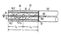
- the figure shows the exemplary laser transmitter with the double core fiber and a system fiber coupled to it, the double core fiber being shown in axial longitudinal section.
- the wavelength-selective fiber directional coupler RK of the external resonator ER consists of a dispersive double-core fiber with a rotationally symmetrical structure.
- the optical waveguide WL1 coupled to the semiconductor laser HL forms the central core of this fiber, which runs along the axis A of this fiber.
- the other optical waveguide WL2 is provided by a coaxial core which surrounds the core WL1 at a distance.
- any dispersive double-core fiber for example any double-core fiber known from DE-OS 34 35 172, is suitable.
- the length of the double core fiber corresponding to the coupling path L of the fiber directional coupler RK is selected to be an integer multiple, in particular the double coupling length L, in which a radiation power St coupled into one of the two waveguides WL1 or WL2 at one end of the waveguide W is completely in the other waveguide WL2 or WL1 is coupled. Accordingly, a radiation power St coupled into one waveguide WL1 at one end of the double core fiber is completely coupled into the other waveguide WL2 in the longitudinal axial center of the double core fiber, while at the other end of the fiber this radiation power is again completely coupled over to one waveguide WL1.
- the partially transparent feedback device RKE is provided in the region of the one waveguide WL1, for example in the form of a partially transparent mirror layer.
- the part of the radiation power with the wavelength ⁇ 0 that has passed through the feedback device RKE is coupled into the core of a system fiber SyF, for example butt-coupled to the double core fiber, and passed on.
- the feedback device must be provided on the end of the double core fiber remote from the semiconductor laser in the region of the waveguide not coupled to the semiconductor laser and the system fiber must be coupled to this waveguide, an optical sump is generally not necessary here, but could be provided, for example, on the end of the fiber remote from the semiconductor laser in the region of the waveguide coupled to this laser.
- the coupling length L0 the wavelength ⁇ 0 of the reflected radiation, the bandwidth and thus the selectivity of the resonator are only determined by the structural parameters of the double core fiber.
- the feedback of part of the power emitted by the semiconductor laser HL forces the laser transmitter to operate in a single mode with a narrow line width. Since the line width of the resulting single-mode spectrum is inversely proportional to the length of the external resonator (see IEEE Journ. Of Quant. Electronics QE-20 (1984) pp. 486ff), a double core fiber with a length that can be used to achieve a smaller line width is a multiple of the coupling length L0.
Landscapes
- Physics & Mathematics (AREA)
- General Physics & Mathematics (AREA)
- Optics & Photonics (AREA)
- Condensed Matter Physics & Semiconductors (AREA)
- Electromagnetism (AREA)
- Semiconductor Lasers (AREA)
- Optical Integrated Circuits (AREA)
- Optical Couplings Of Light Guides (AREA)
- Gyroscopes (AREA)
- Optical Fibers, Optical Fiber Cores, And Optical Fiber Bundles (AREA)
- Light Guides In General And Applications Therefor (AREA)
Abstract
Description
- Die vorliegende Erfindung betrifft einen Lasersender mit einem Halbleiterlaser und einem externen Resonator in Form eines frequenzselektiven Faserrichtkopplers nach dem Oberbegriff des Patentanspruchs 1, bei dem also die Ausgangsleistung aus dem Resonator entnommen wird, der eine Wellenlängenselektivität des Senders bewirkt.
- Ein Sender der genannten Art ist in der älteren deutschen Patentanmeldung P 36 00 726.9 (VPA 86 P 1006 DE) vorgeschlagen (siehe dort Figur 2 und dazugehörigen Beschreibungsteil).
- Bei diesem vorgeschlagenen Sender wird die von dem Halbleiterlaser in den einen Wellenleiter eingekoppelte Strahlungsleistung der teildurchlässigen Rückkopplungseinrichtung zugeleitet und der von der Rückkopplungseinrichtung durchgelassene Teil der Strahlungsleistung wird über einen schleifenförmigen optischen Wellenleiter dem anderen optischen Wellenleiter zugeleitet, an dem die diesen Teil enthaltende Ausgangsleistung des Senders entnommen wird.
- Mit einem derartigen Lasersender kann ein extrem schmalbandiger, einmodiger Betriebszustand erreicht werden, wie er für zukünftige faseroptische Nachrichtenssysteme, insbesondere mit Heterodyn- und Homodynempfang erforderlich ist.
- Ein derartiger Lasersender weist den Vorteil auf, daß die Ankopplung des Resonators und einer Systemfaser an den Halb leiterlaser auf nur einer Seite des Halbleiterlasers erfolgt, in Gegensatz zu anderen Ausführungsform solcher Lasersender, bei denen die Systemfaser auf einer Seite und der Resonator auf der gegenüberliegenden Seite an den Halbleiterlaser angekoppelt sind. Durch die einseitige Ankopplung werden Justierprobleme erheblich vermindert und es kann dem Erfordernis einer hohen mechanischen Stabilität bei der Ankopplung der Systemfaser und des externen Resonators besser entsprochen werden.
- Aufgabe der Erfindung ist es, einen besonders kompakt gestalteten schmalbandigen Sender der eingangs genannten Art mit einseitiger Ankopplung anzugeben, der keinen schleifenförmigen optischen Wellenleiter benötigt.
- Diese Aufgabe wird durch die im kennzeichnenden Teil des Patentanspruchs 1 angegebenen Merkmale gelöst.
- Als dort genannte dispersive Doppelkernfasern sind beispielsweise Fasern geeignet, wie sie in der DE-OS 34 35 172 (VPA 84 P 1752 DE) beschrieben sind. Solche Fasern wirken als stark dispersiver Resonator.
- Besonders hervorzuheben sind bei einem derartigen Resonator die Unempfindlichkeit des Resonators bzw. seiner dispersiven Eigenschaften gegen thermische und mechanische Einflüsse, die nur durch Strukturparameter der Doppelkernfaser bestimmt werden, sowie die einfache Einkopplung in eine anschließende Systemfaser.
- Bevorzugte Ausgestaltungen des erfindungsgemäßen Lasersenders gehen aus den Ansprüchen 2 und 3 hervor.
- Die Erfindung wird anhand der Figur in der folgenden Beschreibung beispielhaft beschrieben.
- Die Figur zeigt den beispielhaften Lasersender mit der Doppelkernfaser und einer daran angekoppelten Systemfaser, wobei die Doppelkernfaser im axialen Längsschnitt dargestellt ist.
- Bei dem dargestellten Beispiel des Lasersenders LS besteht der wellenlängenselektive Faserrichtkoppler RK des externen Resonators ER aus einer dispersiven Doppelkernfaser mit rotationssymmetrischem Aufbau. Den an den Halbleiterlaser HL angekoppelten optischen Wellenleiter WL1 bildet der zentrale Kern dieser Faser, der längs der Achse A dieser Faser verläuft. Der andere optische Wellenleiter WL2 ist durch einen koaxialen, den einen Kern WL1 mit Abstand ummantelnden Kern gegeben.
- Prinzipiell ist jedoch jede dispersive Doppelkernfaser, beispielsweise jede aus der DE-OS 34 35 172 bekannte Doppelkernfaser geeignet.
- Die der Koppelstrecke L des Faserrichtkopplers RK entsprechende Länge der Doppelkernfaser ist gleich einem ganzzahligen Vielfachen, speziell der doppelten Überkopplungslänge L₀ gewählt, bei der eine an einem Ende der Doppelkernfaser in einen der beiden Wellenleiter WL1 oder WL2 eingekoppelte Strahlungsleistung St vollständig in den anderen Wellenleiter WL2 bzw. WL1 übergekoppelt ist. Demnach ist eine an einem Ende der Doppelkernfaser in den einen Wellenleiter WL1 eingekoppelte Strahlungsleistung St in der längsaxialen Mitte der Doppelkernfaser vollständig in den anderen Wellenleiter WL2 übergekoppelt, während am anderen Ende der Faser diese Strahlungsleistung wieder vollständig auf den einen Wellenleiter WL1 übergekoppelt ist.
- Übergekoppelt wird dabei wird dabei nur eine Strahlungsleistung einer gewünschten Wellenlänge λ₀. Strahlungsleistung mit einer von der gewünschten Wellenlänge λ₀ verschiedenen Wellenlänge λ wird ohne Überkopplung längs des einen Wellenleiters WL1 vom einen zum anderen Ende der Doppelkernfaser überführt. Dieser eine Wellenleiter WL1 wird nach der einfachen Überkopplungslänge L₀, also in der längsaxialen Mitte der Doppelkernfaser, bei welcher Strahlungsleistung der Wellenlänge λ₀ von dem einen Wellenleiter WL1 vollständig in den anderen Wellenleiter WL2 übergekoppelt ist, durch einen optischen Sumpf OS unterbrochen, so daß Strahlungsleistung mit einer von der Wellenlänge λ₀ verschiedenen Wellenlänge λ nicht zu dem von dem Halbleiterlaser HL abgekehrten Ende EF der Doppelkernfaser gelangen kann, sondern im wesentlichen nur Strahlungsleistung der Wellenlänge λ₀.
- An diesem anderen Ende EF der Doppelkernfaser ist die teildurchlässige Rückkopplungseinrichtung RKE im Bereich des einen Wellenleiters WL1 beispielsweise in Form einer teildurchlässigen Spiegelschicht vorgesehen.
- Der durch die Rückkopplungseinrichtung RKE hindurchgegangene teil der Strahlungsleistung mit der Wellenlänge λ₀ wird in den Kern einer an die Doppelkernfaser beispielsweise stoßgekoppelte Systemfaser SyF eingekoppelt und fortgeleitet.
- Wird eine Doppelkernfaser mit nur der einfachen Überkopplungslänge L₀ oder einem ungeradzahligen Vielfachen davon verwendet, ist die Rückkopplungseinrichtung an dem von dem Halbleiterlaser abgekehrten Ende der Doppelkernfaser im Bereich des nicht an den Halbleiterlaser angekoppelten Wellenleiters vorzusehen und die Systemfaser ist an diesen Wellenleiter anzukoppeln, Ein optischer Sumpf ist hier im allgemeinen nicht erforderlich, könnte aber beispielsweise an dem von dem Halbleiterlaser abgekehrten Ende der Faser im Bereich des an diesen Laser angekoppelten Wellenleiters vorgesehen sein.
- Generell gilt, daß die Überkopplungslänge L₀ die Wellenlänge λ₀ der reflektierten Strahlung, die Bandbreite und damit die Selektivität des Resonators nur von den Strukturparametern der Doppelkernfaser bestimmt werden.
- Durch die Rückkopplung eines Teils der vom Halbleiterlaser HL ausgestrahlten Leistung wird ein einmodiger Betrieb des Lasersenders mit schmaler Linienbreite erzwungen. Da die Linienbreite des sich ergebenden Einmodenspektrums der Länge des externen Resonators umgekehrt proportional ist (siehe dazu IEEE Journ. of Quant. Electronics QE-20 (1984) S. 486ff) kann zur Erzielung einer kleineren Linienbreite eine Doppelkernfaser mit einer Länge verwendet werden, die ein Vielfaches der Überkopplungslänge L₀ beträgt.
- Es ist zweckmäßig, die von dem externen Resonator ER abgekehrte Seite des Halbleiterkörpers zu verspiegel. Dadurch steigt die optische Leistung bei gleichem Pumpsystem aufgrund der Schwellstromerniedrigung und die Empfindlichkeit bezüglich parasitärer Reflexionen sinkt. Dies gilt für alle Lasersender mit externem Resonator und einseitiger Ankopplung, d.h. bei denen die Ausgangsleistung des Senders auf der Seite des Resonators entnommen wird.
Claims (3)
dadurch gekennzeichnet,
daß der frequenzselektive Faserrichtkoppler (RK) aus einer dispersiven Doppelkernfaser besteht, wobei ein Kern den einen an den Halbleiterlaser (HL) angekoppelten Wellenleiter (WL1) und der andere Kern den anderen Wellenleiter (WL2) bildet,
daß der Rückkopplungseinrichtung (RKE) eine in der Koppelstrecke (L) von dem einen Wellenleiter (WL1) in den anderen Wellenleiter (WL2) übergekoppelte Strahlungsleistung zugeleitet ist, und
daß der von der Rückkopllungseinrichtung (RKE) durchgelassene Teil dieser übergekoppelten Strahlungsleistung die Ausgangsleistung (ASt) des Senders (LS) bildet.
Priority Applications (1)
| Application Number | Priority Date | Filing Date | Title |
|---|---|---|---|
| AT87112825T ATE83090T1 (de) | 1986-09-29 | 1987-09-02 | Lasersender mit einem halbleiterlaser und einem externen optischen resonator in form eines frequenzselektiven faserrichtkopplers. |
Applications Claiming Priority (2)
| Application Number | Priority Date | Filing Date | Title |
|---|---|---|---|
| DE3633077 | 1986-09-29 | ||
| DE3633077 | 1986-09-29 |
Publications (3)
| Publication Number | Publication Date |
|---|---|
| EP0262438A2 true EP0262438A2 (de) | 1988-04-06 |
| EP0262438A3 EP0262438A3 (en) | 1989-10-11 |
| EP0262438B1 EP0262438B1 (de) | 1992-12-02 |
Family
ID=6310608
Family Applications (1)
| Application Number | Title | Priority Date | Filing Date |
|---|---|---|---|
| EP87112825A Expired - Lifetime EP0262438B1 (de) | 1986-09-29 | 1987-09-02 | Lasersender mit einem Halbleiterlaser und einem externen optischen Resonator in Form eines frequenzselektiven Faserrichtkopplers |
Country Status (5)
| Country | Link |
|---|---|
| US (1) | US4799234A (de) |
| EP (1) | EP0262438B1 (de) |
| JP (1) | JPS6394202A (de) |
| AT (1) | ATE83090T1 (de) |
| DE (1) | DE3782909D1 (de) |
Cited By (2)
| Publication number | Priority date | Publication date | Assignee | Title |
|---|---|---|---|---|
| FR2684454A1 (fr) * | 1991-12-03 | 1993-06-04 | Alsthom Cge Alcatel | Composant optique monolithique ayant au moins une fonction de derivation de l'energie incidente. |
| WO1995032451A1 (en) * | 1994-05-19 | 1995-11-30 | University Of Southampton | Optical devices |
Families Citing this family (8)
| Publication number | Priority date | Publication date | Assignee | Title |
|---|---|---|---|---|
| US5023885A (en) * | 1988-09-20 | 1991-06-11 | Siemens Aktiengesellschaft | External optical resonator for a semiconductor laser |
| WO1991001056A1 (en) * | 1989-07-06 | 1991-01-24 | Australian Electro Optics Pty. Ltd. | Segmented, fibre coupled diode laser arrays |
| US5309542A (en) * | 1991-09-18 | 1994-05-03 | International Business Machines Corporation | Fiber optic transmitter modification for improved extinction ratio |
| US5319652A (en) * | 1993-01-29 | 1994-06-07 | The United States Of America As Represented By The Secretary Of The Navy | Super luminescent light source |
| US5493127A (en) * | 1994-12-20 | 1996-02-20 | Michigan State University | Feedback control of electrorheological fluid response |
| AU691783B3 (en) * | 1996-08-01 | 1998-05-21 | Kingfisher International Pty. Ltd. | An optical source |
| FR2809212B1 (fr) | 2000-05-18 | 2002-08-30 | Inrets | Systeme de comptage d'etres vivants |
| US20040028336A1 (en) * | 2001-09-04 | 2004-02-12 | Feuer Mark D. | Method for fabricating optical devices by assembling multiple wafers containing planar optical waveguides |
Family Cites Families (4)
| Publication number | Priority date | Publication date | Assignee | Title |
|---|---|---|---|---|
| US4363533A (en) * | 1979-12-26 | 1982-12-14 | Gould Inc. | Concentric fiber optical transducer |
| US4372643A (en) * | 1980-06-23 | 1983-02-08 | Bell Telephone Laboratories, Incorporated | Standing-wave, velocity-matched gate |
| DE3138968A1 (de) * | 1981-09-30 | 1983-04-14 | Siemens AG, 1000 Berlin und 8000 München | Optische steuervorrichtung zum steuern der in einem optischen wellenleiter gefuehrten strahlung, insbesondere optischer schalter |
| US4748687A (en) * | 1984-09-25 | 1988-05-31 | Siemens Aktiengesellschaft | Narrow band laser transmitter |
-
1987
- 1987-09-02 DE DE8787112825T patent/DE3782909D1/de not_active Expired - Fee Related
- 1987-09-02 AT AT87112825T patent/ATE83090T1/de not_active IP Right Cessation
- 1987-09-02 EP EP87112825A patent/EP0262438B1/de not_active Expired - Lifetime
- 1987-09-14 US US07/095,886 patent/US4799234A/en not_active Expired - Fee Related
- 1987-09-24 JP JP62242407A patent/JPS6394202A/ja active Pending
Cited By (3)
| Publication number | Priority date | Publication date | Assignee | Title |
|---|---|---|---|---|
| FR2684454A1 (fr) * | 1991-12-03 | 1993-06-04 | Alsthom Cge Alcatel | Composant optique monolithique ayant au moins une fonction de derivation de l'energie incidente. |
| WO1995032451A1 (en) * | 1994-05-19 | 1995-11-30 | University Of Southampton | Optical devices |
| US5930435A (en) * | 1994-05-19 | 1999-07-27 | University Of Southampton | Optical filter device |
Also Published As
| Publication number | Publication date |
|---|---|
| EP0262438B1 (de) | 1992-12-02 |
| JPS6394202A (ja) | 1988-04-25 |
| ATE83090T1 (de) | 1992-12-15 |
| US4799234A (en) | 1989-01-17 |
| EP0262438A3 (en) | 1989-10-11 |
| DE3782909D1 (de) | 1993-01-14 |
Similar Documents
| Publication | Publication Date | Title |
|---|---|---|
| DE3688687T2 (de) | Zusatzresonator. | |
| DE69005794T2 (de) | Optische Verstärkungseinrichtung mit niedrigem Rauschen und Reflexion der Pumpleistung. | |
| DE69414139T2 (de) | Kopplungsanordnung zwischen einer multimodalen lichtquelle und einer optischen faser mittels eines faserzwischenstücks | |
| DE3750149T2 (de) | Filterabzweigung in optischen Kommunikationssystemen. | |
| DE69800007T2 (de) | Vorrichtung mit kaskadiertem Ramanfaserlaser | |
| DE69729832T2 (de) | Vorrichtung mit durch die Umhüllung gepumptem faseroptischen Laser | |
| DE69900082T2 (de) | Vorrichtung mit einem verbesserten kaskadiertem Ramanfaserlaser | |
| DE69027378T2 (de) | Optisches Übertragungssystem | |
| DE69022129T2 (de) | Lichtverstärker mit optischer Faser. | |
| EP0012189B1 (de) | Koppelelement zum Auskoppeln eines Lichtanteils aus einem einen Kern und einen Mantel aufweisenden Glasfaser-Lichtwellenleiter | |
| DE69013003T2 (de) | Interferometer unter benutzung superfluoreszierender optischer quellen. | |
| DE2745940A1 (de) | Optisches schaltkreiselement | |
| DE69412472T2 (de) | Laser | |
| DE69026815T2 (de) | Optischer verstärker | |
| DE2842276A1 (de) | Ein-/auskoppelelement | |
| DE3135875A1 (de) | Optisches uebertragungssystem | |
| DE69913928T2 (de) | Mehrwellenlängen-Quelle | |
| EP0262438B1 (de) | Lasersender mit einem Halbleiterlaser und einem externen optischen Resonator in Form eines frequenzselektiven Faserrichtkopplers | |
| EP2478400B1 (de) | Transversalmodenfilter für wellenleiter | |
| DE69122766T2 (de) | Optisches netzwerk | |
| EP0101078A2 (de) | Sende- und Empfangseinrichtung für ein faseroptisches Sensorsystem | |
| DE3232212A1 (de) | Optisches multiplex-nachrichtenuebertragungssystem | |
| DE3785811T2 (de) | Kurzschlitz-hybridkoppler grosser bandbreite. | |
| EP0262435A2 (de) | Schmalbandiger Lasersender mit einem externen Resonator, bei dem die Ausgangsleistung dem Resonator entnehmbar ist | |
| EP0216212A2 (de) | Externer optischer Resonator für einen Halbleiterlaser |
Legal Events
| Date | Code | Title | Description |
|---|---|---|---|
| PUAI | Public reference made under article 153(3) epc to a published international application that has entered the european phase |
Free format text: ORIGINAL CODE: 0009012 |
|
| AK | Designated contracting states |
Kind code of ref document: A2 Designated state(s): AT BE CH DE ES FR GB GR IT LI NL SE |
|
| PUAL | Search report despatched |
Free format text: ORIGINAL CODE: 0009013 |
|
| AK | Designated contracting states |
Kind code of ref document: A3 Designated state(s): AT BE CH DE ES FR GB GR IT LI NL SE |
|
| 17P | Request for examination filed |
Effective date: 19900328 |
|
| 17Q | First examination report despatched |
Effective date: 19911024 |
|
| GRAA | (expected) grant |
Free format text: ORIGINAL CODE: 0009210 |
|
| AK | Designated contracting states |
Kind code of ref document: B1 Designated state(s): AT BE CH DE ES FR GB GR IT LI NL SE |
|
| PG25 | Lapsed in a contracting state [announced via postgrant information from national office to epo] |
Ref country code: IT Free format text: LAPSE BECAUSE OF FAILURE TO SUBMIT A TRANSLATION OF THE DESCRIPTION OR TO PAY THE FEE WITHIN THE PRE;WARNING: LAPSES OF ITALIAN PATENTS WITH EFFECTIVE DATE BEFORE 2007 MAY HAVE OCCURRED AT ANY TIME BEFORE 2007. THE CORRECT EFFECTIVE DATE MAY BE DIFFERENT FROM THE ONE RECORDED.SCRIBED TIME-LIMIT Effective date: 19921202 Ref country code: GR Free format text: LAPSE BECAUSE OF FAILURE TO SUBMIT A TRANSLATION OF THE DESCRIPTION OR TO PAY THE FEE WITHIN THE PRESCRIBED TIME-LIMIT Effective date: 19921202 Ref country code: BE Effective date: 19921202 Ref country code: GB Effective date: 19921202 Ref country code: FR Effective date: 19921202 Ref country code: NL Effective date: 19921202 Ref country code: SE Effective date: 19921202 |
|
| REF | Corresponds to: |
Ref document number: 83090 Country of ref document: AT Date of ref document: 19921215 Kind code of ref document: T |
|
| REF | Corresponds to: |
Ref document number: 3782909 Country of ref document: DE Date of ref document: 19930114 |
|
| PG25 | Lapsed in a contracting state [announced via postgrant information from national office to epo] |
Ref country code: ES Free format text: LAPSE BECAUSE OF FAILURE TO SUBMIT A TRANSLATION OF THE DESCRIPTION OR TO PAY THE FEE WITHIN THE PRESCRIBED TIME-LIMIT Effective date: 19930313 |
|
| EN | Fr: translation not filed | ||
| NLV1 | Nl: lapsed or annulled due to failure to fulfill the requirements of art. 29p and 29m of the patents act | ||
| GBV | Gb: ep patent (uk) treated as always having been void in accordance with gb section 77(7)/1977 [no translation filed] |
Effective date: 19921202 |
|
| PG25 | Lapsed in a contracting state [announced via postgrant information from national office to epo] |
Ref country code: AT Effective date: 19930902 |
|
| PG25 | Lapsed in a contracting state [announced via postgrant information from national office to epo] |
Ref country code: CH Effective date: 19930930 Ref country code: LI Effective date: 19930930 |
|
| PLBE | No opposition filed within time limit |
Free format text: ORIGINAL CODE: 0009261 |
|
| STAA | Information on the status of an ep patent application or granted ep patent |
Free format text: STATUS: NO OPPOSITION FILED WITHIN TIME LIMIT |
|
| PGFP | Annual fee paid to national office [announced via postgrant information from national office to epo] |
Ref country code: DE Payment date: 19931119 Year of fee payment: 7 |
|
| 26N | No opposition filed | ||
| REG | Reference to a national code |
Ref country code: CH Ref legal event code: PL |
|
| PG25 | Lapsed in a contracting state [announced via postgrant information from national office to epo] |
Ref country code: DE Effective date: 19950601 |