EP0262460A2 - Dispositif d'attribution optimale de poids à des coefficients de transformation transmis auprès de codeurs par transformation dans le but de minimaliser les distorsions de repliement - Google Patents
Dispositif d'attribution optimale de poids à des coefficients de transformation transmis auprès de codeurs par transformation dans le but de minimaliser les distorsions de repliement Download PDFInfo
- Publication number
- EP0262460A2 EP0262460A2 EP87112981A EP87112981A EP0262460A2 EP 0262460 A2 EP0262460 A2 EP 0262460A2 EP 87112981 A EP87112981 A EP 87112981A EP 87112981 A EP87112981 A EP 87112981A EP 0262460 A2 EP0262460 A2 EP 0262460A2
- Authority
- EP
- European Patent Office
- Prior art keywords
- transmitted
- coefficients
- transformation
- output
- input
- Prior art date
- Legal status (The legal status is an assumption and is not a legal conclusion. Google has not performed a legal analysis and makes no representation as to the accuracy of the status listed.)
- Withdrawn
Links
Images


Classifications
-
- H—ELECTRICITY
- H04—ELECTRIC COMMUNICATION TECHNIQUE
- H04N—PICTORIAL COMMUNICATION, e.g. TELEVISION
- H04N19/00—Methods or arrangements for coding, decoding, compressing or decompressing digital video signals
- H04N19/10—Methods or arrangements for coding, decoding, compressing or decompressing digital video signals using adaptive coding
- H04N19/102—Methods or arrangements for coding, decoding, compressing or decompressing digital video signals using adaptive coding characterised by the element, parameter or selection affected or controlled by the adaptive coding
- H04N19/124—Quantisation
- H04N19/126—Details of normalisation or weighting functions, e.g. normalisation matrices or variable uniform quantisers
-
- H—ELECTRICITY
- H04—ELECTRIC COMMUNICATION TECHNIQUE
- H04N—PICTORIAL COMMUNICATION, e.g. TELEVISION
- H04N19/00—Methods or arrangements for coding, decoding, compressing or decompressing digital video signals
- H04N19/60—Methods or arrangements for coding, decoding, compressing or decompressing digital video signals using transform coding
- H04N19/61—Methods or arrangements for coding, decoding, compressing or decompressing digital video signals using transform coding in combination with predictive coding
- H04N19/619—Methods or arrangements for coding, decoding, compressing or decompressing digital video signals using transform coding in combination with predictive coding the transform being operated outside the prediction loop
-
- H—ELECTRICITY
- H04—ELECTRIC COMMUNICATION TECHNIQUE
- H04N—PICTORIAL COMMUNICATION, e.g. TELEVISION
- H04N19/00—Methods or arrangements for coding, decoding, compressing or decompressing digital video signals
- H04N19/10—Methods or arrangements for coding, decoding, compressing or decompressing digital video signals using adaptive coding
- H04N19/102—Methods or arrangements for coding, decoding, compressing or decompressing digital video signals using adaptive coding characterised by the element, parameter or selection affected or controlled by the adaptive coding
- H04N19/124—Quantisation
-
- H—ELECTRICITY
- H04—ELECTRIC COMMUNICATION TECHNIQUE
- H04N—PICTORIAL COMMUNICATION, e.g. TELEVISION
- H04N19/00—Methods or arrangements for coding, decoding, compressing or decompressing digital video signals
- H04N19/60—Methods or arrangements for coding, decoding, compressing or decompressing digital video signals using transform coding
Definitions
- the present invention relates to an arrangement for the optimized weighting of transmitted transformation coefficients in transformation encoders for the purpose of minimizing convolution coefficients.
- the buffer controller can influence the transmission rate by specifying the number of transformation coefficients to be transmitted, cf. B. German patent application P 35 13 877.7 ("Method for image data reduction for digital television signals"). This limitation of the number of coefficients to be transmitted can lead to convolution distortions in the reconstructed signal at the output of the receiver, which distortions are particularly noticeable at the edges of objects.
- the present invention has for its object a To create arrangement of the type mentioned, which can eliminate the problem described.
- the convolution distortions can be avoided if, according to the invention, the coefficients to be transmitted are additionally subjected to a weighting ("windowing").
- the selection of the suitable weighting factors which minimize the convolution distortions in the reconstructed image takes place as a function of the number of the coefficients to be transmitted.
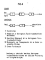
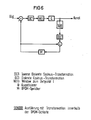
- FIG. 1 shows a schematic illustration, specifically in the form of a block diagram, of such an arrangement for the optimized weighting of transmitted transformation coefficients.
- a transmitter to which an image signal is fed has a structure with a series circuit consisting of a transformation stage T, a selector stage S for selecting the transformation coefficients to be transmitted and a weighting stage W for weighting (windowing) the ones to be transmitted Transformation coefficients, and a matching receiver on the other side of the channel has a structure with a series connection, consisting of a compensation stage IW for compensation or partial compensation of the "Windows" used in the transmitter and a transformation stage IT for inverse transformation for the restoration the image signal.
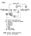
- FIG. 2 shows a first exemplary embodiment for a transmitter with "window compensation" after the DPCM memory.
- the image signal is first fed to a discrete cosine transformation DCT.
- This transformation is followed by a stage W (t) for forming a "window” for image scenes at time t.
- the output of this stage W (t) is led to a first input of a subtraction element, the output of which is connected to a quantizer Q.
- the output of the quantizer Q is connected to an analysis stage A, a coder C and a first input of a summing element.
- the output of the summing element is connected to the input of a DPCM memory M, to which an output signal of analysis stage A, namely a class signal, is fed via a side input, which is also fed to a so-called window manager WM.
- the output of the DPCM memory M is connected to an input of a processing stage W (t) / W (t-1), to which an output signal of the window manager WM is fed via a further input.
- An output of the processing stage is connected to the second input of the subtraction element and also to the further input of the summing element.
- the output of the encoder C is connected to the input of a buffer B, the output of which leads to the channel.
- Another output of buffer B is connected to an input of a buffer controller BC, the output of which is connected to a second input of analysis stage A, another input of window manager WM and another input of processing stage W (t) / W (t-1) connected is.
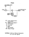
- FIG. 3 shows a block diagram of a first exemplary embodiment for a receiver with "window compensation" after the DPCM memory.
- the channel is connected at the input to the input of a buffer B, an output of which has a first input of a summing element and a further output of which Input of a buffer controller BC is connected.
- the output of the summing element is connected to an IDCT stage for inverse discrete cosine transformation, the output of which emits a reconstructed image signal.
- the output of the summing element is connected to the input of a DPCM memory M, the output of which is connected to a processing stage W (t) / W (t-1), where W (t) stands for a "window" at time t.
- An output of this processing stage is connected to the further input of the summing element.
- the output of the buffer regulator BC which emits a window selection signal, is connected to an input of a window manager WM and a further input of the processing stage, and an output of the window manager WM is connected to a third input of the processing stage.
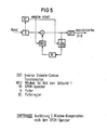
- Fig. 4 u. 5 show, in the manner shown therein, different embodiments of the transmitter or of the receiver.
- FIGS. 2 to 5 are such that they enable an optimized weighting in cooperation with the already proposed DCT hybrid encoder according to German patent application P 35 13 877.7.
- FIG. 6 shows the block diagram of a transmitter according to a further exemplary embodiment of the invention.
- the transformation within the DPCM loop is carried out in this transmitter.
- This circuit arrangement is particularly cost-effective because it contains significantly fewer elements than the circuit arrangements explained above, which also applies to the Circuit arrangement shown in Fig. 7 applies to the receiver.
Landscapes
- Engineering & Computer Science (AREA)
- Multimedia (AREA)
- Signal Processing (AREA)
- Compression Or Coding Systems Of Tv Signals (AREA)
- Compression, Expansion, Code Conversion, And Decoders (AREA)
Applications Claiming Priority (2)
| Application Number | Priority Date | Filing Date | Title |
|---|---|---|---|
| DE3633185 | 1986-09-30 | ||
| DE3633185 | 1986-09-30 |
Publications (2)
| Publication Number | Publication Date |
|---|---|
| EP0262460A2 true EP0262460A2 (fr) | 1988-04-06 |
| EP0262460A3 EP0262460A3 (fr) | 1989-10-25 |
Family
ID=6310665
Family Applications (1)
| Application Number | Title | Priority Date | Filing Date |
|---|---|---|---|
| EP87112981A Withdrawn EP0262460A3 (fr) | 1986-09-30 | 1987-09-04 | Dispositif d'attribution optimale de poids à des coefficients de transformation transmis auprès de codeurs par transformation dans le but de minimaliser les distorsions de repliement |
Country Status (3)
| Country | Link |
|---|---|
| US (1) | US4862263A (fr) |
| EP (1) | EP0262460A3 (fr) |
| JP (1) | JPS6390982A (fr) |
Cited By (1)
| Publication number | Priority date | Publication date | Assignee | Title |
|---|---|---|---|---|
| EP0382892A1 (fr) * | 1989-02-14 | 1990-08-22 | Mitsubishi Denki Kabushiki Kaisha | Dispositif pour coder et décoder des signaux d'image |
Families Citing this family (11)
| Publication number | Priority date | Publication date | Assignee | Title |
|---|---|---|---|---|
| US5691777A (en) * | 1988-10-17 | 1997-11-25 | Kassatly; Lord Samuel Anthony | Method and apparatus for simultaneous compression of video, audio and data signals |
| JPH02295278A (ja) * | 1989-05-09 | 1990-12-06 | Nec Corp | 濃淡画像信号の変換符号化復号化方法とその装置 |
| US4994927A (en) * | 1989-06-19 | 1991-02-19 | Gte Laboratories Inc | Self-adaptive neural net based vector quantizer for image compression |
| EP0514663A3 (en) * | 1991-05-24 | 1993-07-14 | International Business Machines Corporation | An apparatus and method for motion video encoding employing an adaptive quantizer |
| EP0535272A1 (fr) * | 1991-10-02 | 1993-04-07 | Alcatel N.V. | Codeur hybride pour un système de traitement d'images |
| US5636295A (en) * | 1992-10-07 | 1997-06-03 | Daewoo Electronics Co., Ltd. | Apparatus for reducing quantization noise in image signals |
| JP3058028B2 (ja) * | 1994-10-31 | 2000-07-04 | 三菱電機株式会社 | 画像符号化データ再符号化装置 |
| FI97495C (fi) * | 1995-02-06 | 1996-12-27 | Nokia Technology Gmbh | Menetelmä kuvan terävöittämiseksi |
| JP2914226B2 (ja) * | 1995-06-16 | 1999-06-28 | 日本電気株式会社 | 可逆変換を可能にするディジタル信号の変換符号化方式 |
| US5706216A (en) * | 1995-07-28 | 1998-01-06 | Reisch; Michael L. | System for data compression of an image using a JPEG compression circuit modified for filtering in the frequency domain |
| JP3274593B2 (ja) | 1995-09-27 | 2002-04-15 | 日本電気株式会社 | 可逆変換可能な変換装置及び逆変換装置 |
Family Cites Families (5)
| Publication number | Priority date | Publication date | Assignee | Title |
|---|---|---|---|---|
| IT1155557B (it) * | 1982-07-19 | 1987-01-28 | Cselt Centro Studi Lab Telecom | Metdodo e dispositivo per la codifica del segnale d immagine con riduzione di ridondanza a distorsione localmente uniforme |
| GB8429879D0 (en) * | 1984-11-27 | 1985-01-03 | Rca Corp | Signal processing apparatus |
| ATE61703T1 (de) * | 1985-04-17 | 1991-03-15 | Siemens Ag | Verfahren zur bilddatenreduktion fuer digitale fernsehsignale. |
| US4709394A (en) * | 1985-08-23 | 1987-11-24 | Rca Corporation | Multiplexed real-time pyramid signal processing system |
| US4698689A (en) * | 1986-03-28 | 1987-10-06 | Gte Laboratories Incorporated | Progressive image transmission |
-
1987
- 1987-09-04 EP EP87112981A patent/EP0262460A3/fr not_active Withdrawn
- 1987-09-28 JP JP62245742A patent/JPS6390982A/ja active Pending
- 1987-09-30 US US07/103,111 patent/US4862263A/en not_active Expired - Fee Related
Cited By (3)
| Publication number | Priority date | Publication date | Assignee | Title |
|---|---|---|---|---|
| EP0382892A1 (fr) * | 1989-02-14 | 1990-08-22 | Mitsubishi Denki Kabushiki Kaisha | Dispositif pour coder et décoder des signaux d'image |
| US5111294A (en) * | 1989-02-14 | 1992-05-05 | Mitsubishi Denki Kabushiki Kaisha | Motion compensated interframe encoding system with adaptive quantization |
| EP0534504A3 (en) * | 1989-02-14 | 1993-06-09 | Mitsubishi Denki Kabushiki Kaisha | Picture signal encoding and decoding apparatus |
Also Published As
| Publication number | Publication date |
|---|---|
| US4862263A (en) | 1989-08-29 |
| JPS6390982A (ja) | 1988-04-21 |
| EP0262460A3 (fr) | 1989-10-25 |
Similar Documents
| Publication | Publication Date | Title |
|---|---|---|
| DE69015695T2 (de) | Einrichtung zur Transformationskodierung. | |
| DE3884802T3 (de) | Verfahren und vorrichtung zur adaptiven blocktransformationscodierung von bildern. | |
| DE69806580T2 (de) | Adaptives filter | |
| DE68914330T2 (de) | Vorrichtung zum Wiedergeben von digitalisierten Bildern mittels einer Fehlerwiederherstellung mit einer geneigten Ebene. | |
| DE2124754C3 (de) | Verfahren und Vorrichtung zur differentiellen Pulscodemodulation | |
| DE69212124T2 (de) | Verfahren und Einrichtung zur Bildkodierung | |
| EP0421186A2 (fr) | Procédé pour coder des segments d'image de forme arbitraire | |
| DE68916480T2 (de) | Fernsehübertragungssystem mit hybrider Kodierschaltung. | |
| DE3426939A1 (de) | Einbettungsquantisierungsvorrichtung fuer ein vektorsignal | |
| DE3038953C2 (de) | Verfahren zur Bandkompression | |
| DE68910552T2 (de) | Verfahren zur Wiederzuordnung der Wahl eines Unterabtastungsverfahrens nach dem Kriterium einer Datenraten-Reduktion einer Folge von Hilfsdaten, die zur Rekonstruktion eines unterabgetasteten, elektronischen Bildes dienen. | |
| DE3626916A1 (de) | Verfahren zur uebertragung eines videosignales | |
| DE69230047T2 (de) | Fernsehsystem zum Übertragen von Bildsignalen in einem digitalen Format | |
| DE2460654A1 (de) | Verfahren und einrichtung zum codieren eines gegebenen informationssignals | |
| DE2432399A1 (de) | Anordnung zur bilduebertragung nach dem dpcm-verfahren | |
| DE3726601C2 (fr) | ||
| EP0336510B1 (fr) | Codeur predictif d'image immobile | |
| DE3545106A1 (de) | Schaltung zur bilddatenreduktion, mustererkennung, etc. | |
| EP0442096A2 (fr) | Dispositif de codage réduisant la largeur de bande pour signaux vidéo | |
| DE3311898C2 (de) | Verfahren zur Störsignalreduktion von digitalen datenreduzierten Fernsehsignalen | |
| EP0200038A2 (fr) | Méthode et dispositif pour déterminer des valeurs de tensions analogiques qui se produisent à des lignes d'abonné d'un système de commutation téléphonique numérique | |
| DE4143204C2 (de) | Quantisierungsverfahren zur Verwendung bei der Bildkompression | |
| WO1992003889A1 (fr) | Procede et dispositif de transformation de donnees video | |
| EP0081223B1 (fr) | Procédé pour la transmission de signaux d'image couleur numériques | |
| DE68919132T2 (de) | Einrichtung zur Videosignalkorrektur. |
Legal Events
| Date | Code | Title | Description |
|---|---|---|---|
| PUAI | Public reference made under article 153(3) epc to a published international application that has entered the european phase |
Free format text: ORIGINAL CODE: 0009012 |
|
| AK | Designated contracting states |
Kind code of ref document: A2 Designated state(s): DE FR GB IT NL SE |
|
| PUAL | Search report despatched |
Free format text: ORIGINAL CODE: 0009013 |
|
| AK | Designated contracting states |
Kind code of ref document: A3 Designated state(s): DE FR GB IT NL SE |
|
| 17P | Request for examination filed |
Effective date: 19891108 |
|
| 17Q | First examination report despatched |
Effective date: 19920407 |
|
| STAA | Information on the status of an ep patent application or granted ep patent |
Free format text: STATUS: THE APPLICATION HAS BEEN WITHDRAWN |
|
| 18W | Application withdrawn |
Withdrawal date: 19920703 |
|
| RIN1 | Information on inventor provided before grant (corrected) |
Inventor name: STROBACH, PETER, DR. Inventor name: HOELZLWIMMER, HERBERT, DIPL.-ING. Inventor name: TENGLER, WALTER, DIPL.-ING. |