EP0262519A2 - Procédé et dispositif pour l'amortissement de la pointe de pression à la fin de la phase de remplissage du moule des machines à couler sous pression - Google Patents
Procédé et dispositif pour l'amortissement de la pointe de pression à la fin de la phase de remplissage du moule des machines à couler sous pression Download PDFInfo
- Publication number
- EP0262519A2 EP0262519A2 EP87113613A EP87113613A EP0262519A2 EP 0262519 A2 EP0262519 A2 EP 0262519A2 EP 87113613 A EP87113613 A EP 87113613A EP 87113613 A EP87113613 A EP 87113613A EP 0262519 A2 EP0262519 A2 EP 0262519A2
- Authority
- EP
- European Patent Office
- Prior art keywords
- piston
- damping
- control
- pressure
- chamber
- Prior art date
- Legal status (The legal status is an assumption and is not a legal conclusion. Google has not performed a legal analysis and makes no representation as to the accuracy of the status listed.)
- Granted
Links
Images



Classifications
-
- B—PERFORMING OPERATIONS; TRANSPORTING
- B22—CASTING; POWDER METALLURGY
- B22D—CASTING OF METALS; CASTING OF OTHER SUBSTANCES BY THE SAME PROCESSES OR DEVICES
- B22D17/00—Pressure die casting or injection die casting, i.e. casting in which the metal is forced into a mould under high pressure
- B22D17/20—Accessories: Details
- B22D17/32—Controlling equipment
Definitions
- the invention relates to a method for damping the pressure peak occurring at the end of the mold filling phase in die casting machines, a hydraulic damping device having a damping chamber being arranged between the piston rod of the drive piston and that of the casting piston, the inflow of which can be locked or released by a control piston with a control edge , wherein the inertia of the control piston which becomes effective when the casting piston is braked is used to open the inlet to the damping space of the damping device, and it also relates to devices for carrying out such a method.
- a first working phase the actual plunger initiates the pressing process at a relatively slow speed, the air still in the press-in cylinder being able to escape therefrom.
- the second working phase in which the plunger continues to move at increased speed, the liquid metal is pressed into the mold.
- the metal is compressed in the mold by a so-called reprint.
- the present invention is essentially concerned with conditions in the second phase of work, at the end of which the plunger with Piston rod is suddenly braked to a complete standstill. As a result, a pressure spike occurs in the metal, which can lead to the fact that the actual mold closing force is overcome and an (undesired) brief opening of the mold cannot be ruled out.
- the pressure peak is measured with appropriate measuring devices, it can be determined that there are actually two pressure peaks.
- the first pressure peak is formed immediately at the end of the rapid mold filling only by the sudden braking of the moving masses of the casting piston rod, coupling and plunger rod. After about one to two milliseconds, the hydraulic pressure peaks due to the braking of the moving oil column.
- the intensity of the first pressure peak can only be measured in the form or by a comparable measuring device, while the second pressure peak can be measured as usual in the drive chamber of the press-in system.
- the casting piston is braked to its standstill within 1 to 2 milliseconds, depending on the volume to be cast and the condition of the die.
- the switching process for connecting a damping device must run as quickly as possible and may only be a fraction of a millisecond. The greater the switching delays that occur here, the greater the reduction in speed that has occurred in the meantime, and thus also the pressure peak height that is formed.
- a damping device of this type is described in DE-A-28 18 061.
- a liquid-filled damping chamber is controlled by a spring-loaded control piston, which is arranged in the direction of movement of the casting piston rod.
- the control is designed so that the control valve works as a pressure valve and the mass of the control valve is deliberately kept small.
- the opening forces of the control valve must be greater than the maximum transmission force of the piston rod in the mold filling phase, which is unfavorable.
- the control valve is flowed through by the hydraulic fluid that fills the damping space, i. H.
- the hydraulic medium present on the spring side of the control valve must be displaced, which has a lengthening and thus undesirable influence on the switching time of the control valve.
- the storage space of the damping is smaller than the volume displaced during the damping, which makes it necessary for an additional storage space to be used via an external connection.
- the control piston responsible for the duration of the switching time of the damping must also be accelerated in the case of damping in this known damping device against its direction of motion during the mold filling process and against the spring force coordinated in accordance with the maximum working pressure in the damping chamber and be moved over a relatively long distance.
- the object of the invention is to improve the method known from this generic prior art in such a way that the switching time of the control valve is shortened even further, and the pressure peaks which occur when braking at the end of the mold filling phase are thereby further reduced.
- this is achieved in a method of the type mentioned at the outset in that the end face of the control piston facing the casting piston is acted upon by a gas with (atmospheric) ambient pressure, but when the plunger returns, until the control edge of the control piston leads to the damping chamber has closed again, the pressure of the gas is increased and / or the pressure in the damping chamber is reduced.
- a gas with (atmospheric) ambient pressure but when the plunger returns, until the control edge of the control piston leads to the damping chamber has closed again, the pressure of the gas is increased and / or the pressure in the damping chamber is reduced.
- the control piston moves due to its inertia at a speed that corresponds to the mold filling speed, wherein here no biasing force opposing this movement has to be overcome by a spring.
- a gaseous medium expediently air
- the front face of the piston in the direction of movement of the piston, which is approximately at ambient pressure (which can be achieved, for example, by the fact that the chamber in the control piston is constantly vented to the outside), that even in the case of the piston movement caused by the inertia of the piston, the opposite force exerted by the gas present there via the front end face of the piston remains approximately the same and does not increase with continuous movement (such as with a spring preload) because the pressure of the gaseous medium is applied Even when moving the control piston forward, it should always be kept as close to ambient pressure as possible.
- the pressure drop in the pressure in the damping chamber of the hydraulic damping fluid which is alternatively provided in the method according to the invention when the plunger returns, is preferably achieved by increasing the volume of the damping chamber for this purpose.
- This increase in volume means that the hydraulic fluid can be sucked back into the damping space as long as the inlet to the damping space is open and the desired pressure reduction can be achieved on the corresponding side of the control piston.
- a device for carrying out this method according to the invention is based on a damping device which has a housing which cooperates with the piston rod of the drive piston and into which a damping piston which cooperates with the piston rod of the casting piston protrudes, between which and the housing a damping space filled with liquid is formed, wherein an inner chamber is provided within the damping piston, in which a control piston is slidably received, which delimits a storage space on its end face facing the inserted end of the damping piston and has a control edge with which an inlet radially from the inner chamber in the damping piston connects the storage space can be closed or released with the damping space.
- either the damping piston is biased by springs against the housing against its direction of insertion and the space in the damping piston opposite the storage space on the other side of the control piston is constantly connected to the environment via an (open) line
- the springs being particularly preferred are arranged between the housing and a stop plate of the damping piston, or that the space in the damping piston opposite the storage space on the other side of the control piston is connected by means of a line to a control valve via which it can be vented to the outside and when the drive piston returns until the valve closes Inlet through the control edge of the control piston to a compressed gas line (preferably compressed air line) can be connected, in which case preferably the vent connection of the control valve to a gas accumulator preselectable pressure levels, which preferably corresponds to the ambient pressure ht, can be connected, for example by directly connecting to the environment is vented.
- a compressed gas line preferably compressed air line
- a line connecting the storage space to the damping space is preferably provided in the end wall of the damping piston, in which line a non-return valve is attached, which blocks in a flow direction towards the storage space.
- the springs press the damping insert, i. H. the damping piston and the housing apart and the resulting negative pressure in the damping space and storage space sucks the control piston into its basic position as a starting position for a new use.
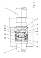
- the control edge 11 formed by a damping piston 3 and a control piston 4 blocks the connection or the opening of the inlet 30 between the damping space 9, which is formed between the housing 6 and the damping piston 3, to the storage space 10 between the damping piston 3 and the control piston 4.
- the the storage space 10 on the control piston 4 opposite space 25 is continuously connected via a vent line 26 to the environment (atmosphere), so that an ongoing pressure equalization between the environment and this space 25 can take place and it is ensured that the pressure in the space 25 is always about corresponds to the ambient pressure.
- the inertia of the control piston 4 reinforces the locking effect of the control edge 11 at the high acceleration which occurs during the rapid mold filling movement, as a result of which the force of the piston rod 2 from Drive piston 15 can be transferred to the piston rod 1 of the casting piston 14 via the intermediate hydraulic medium in the storage space 9.
- compression springs 31 are arranged in corresponding receptacles in the housing 6 in the radial, annular outer region of the housing 6, which encloses the receiving opening for the damping piston 3, in such a way that they can be seen in FIG 3 shown position of the damping device at the end of the damping process are compressed with a sufficiently strong force, which makes it possible for these springs 31 to push the housing 6 away from the stop plate 13 when the piston rod 2 of the drive piston 15 is relieved of pressure and the same is initiated when it is retracted.
- FIGS. 4 and 5 corresponding parts are again designated with corresponding reference numerals as in FIGS. 2 and 3.
- the structure of the embodiment according to FIGS. 4 and 5 differs from that according to FIGS. 2 and 3 only in that no springs are provided between the housing 6 and a support plate here, rather the connecting line 26, which starts from the space 25 , is connected to a control valve 27 which on the one hand has a vent connection 28 and on the other hand a connection to a compressed air line 29 which is connected to a pressure level (not shown) adjustable pressure level.
- the valve 27 is connected to the environment at the connection 28, i. H. In the venting position of the valve 27, the space 25 is vented into the environment via the connecting line 26.
Landscapes
- Engineering & Computer Science (AREA)
- Mechanical Engineering (AREA)
- Fluid-Damping Devices (AREA)
Applications Claiming Priority (4)
| Application Number | Priority Date | Filing Date | Title |
|---|---|---|---|
| DE3632925 | 1986-09-27 | ||
| DE19863632926 DE3632926A1 (de) | 1986-09-27 | 1986-09-27 | Verfahren und vorrichtung zur daempfung der am ende der formfuellphase auftretenden druckspitze bei druckgiessmaschinen |
| DE19863632925 DE3632925A1 (de) | 1986-09-27 | 1986-09-27 | Verfahren und vorrichtung zur daempfung der am ende der formfuellphase auftretenden druckspitze bei druckgiessmaschinen |
| DE3632926 | 1986-09-27 |
Publications (3)
| Publication Number | Publication Date |
|---|---|
| EP0262519A2 true EP0262519A2 (fr) | 1988-04-06 |
| EP0262519A3 EP0262519A3 (en) | 1989-02-01 |
| EP0262519B1 EP0262519B1 (fr) | 1990-07-18 |
Family
ID=25847920
Family Applications (1)
| Application Number | Title | Priority Date | Filing Date |
|---|---|---|---|
| EP87113613A Expired - Lifetime EP0262519B1 (fr) | 1986-09-27 | 1987-09-17 | Procédé et dispositif pour l'amortissement de la pointe de pression à la fin de la phase de remplissage du moule des machines à couler sous pression |
Country Status (2)
| Country | Link |
|---|---|
| EP (1) | EP0262519B1 (fr) |
| DE (1) | DE3763790D1 (fr) |
Cited By (4)
| Publication number | Priority date | Publication date | Assignee | Title |
|---|---|---|---|---|
| AU632711B2 (en) * | 1990-10-15 | 1993-01-07 | Nippondenso Co. Ltd. | Method of discriminating quality of die-cast article and die-casting process using same |
| WO2007034002A1 (fr) * | 2005-09-16 | 2007-03-29 | Urpemak, S.L. | Mecanisme d'injection d'un materiau dans un moule servant a une machine a injection |
| CN111644593A (zh) * | 2020-06-30 | 2020-09-11 | 辽宁天海津城装备制造有限公司 | 一种降低压射冲击的压射缓冲装置 |
| WO2023046891A1 (fr) | 2021-09-24 | 2023-03-30 | Entec-Stracon Gmbh | Dispositif et procédé pour remplir un moule d'une machine de moulage sous pression |
Family Cites Families (3)
| Publication number | Priority date | Publication date | Assignee | Title |
|---|---|---|---|---|
| DE2818061A1 (de) * | 1978-04-25 | 1979-11-08 | Lucas Industries Ltd | Spritzgussmaschine |
| DE3433121C1 (de) * | 1984-09-08 | 1985-12-05 | Maschinenfabrik Müller-Weingarten AG, 7987 Weingarten | Verfahren und Vorrichtung zur Dämpfung der am Ende der Formfüllphase auftretenden Druckspitze bei Druckgießmaschinen |
| DE3446836A1 (de) * | 1984-12-21 | 1986-07-03 | Mahle Gmbh, 7000 Stuttgart | Einrichtung zur druckspitzenverhinderung in dem pressaggregat einer druckgiessmaschine |
-
1987
- 1987-09-17 EP EP87113613A patent/EP0262519B1/fr not_active Expired - Lifetime
- 1987-09-17 DE DE8787113613T patent/DE3763790D1/de not_active Expired - Lifetime
Cited By (6)
| Publication number | Priority date | Publication date | Assignee | Title |
|---|---|---|---|---|
| AU632711B2 (en) * | 1990-10-15 | 1993-01-07 | Nippondenso Co. Ltd. | Method of discriminating quality of die-cast article and die-casting process using same |
| US5363899A (en) * | 1990-10-15 | 1994-11-15 | Nippondenso Co., Ltd. | Method of discriminating quality of die-cast article and die-casting process using same |
| WO2007034002A1 (fr) * | 2005-09-16 | 2007-03-29 | Urpemak, S.L. | Mecanisme d'injection d'un materiau dans un moule servant a une machine a injection |
| CN111644593A (zh) * | 2020-06-30 | 2020-09-11 | 辽宁天海津城装备制造有限公司 | 一种降低压射冲击的压射缓冲装置 |
| WO2023046891A1 (fr) | 2021-09-24 | 2023-03-30 | Entec-Stracon Gmbh | Dispositif et procédé pour remplir un moule d'une machine de moulage sous pression |
| DE102021124780A1 (de) | 2021-09-24 | 2023-03-30 | Entec-Stracon Gmbh | Vorrichtung und Verfahren zur Füllung einer Gießform einer Druckgießmaschine |
Also Published As
| Publication number | Publication date |
|---|---|
| EP0262519B1 (fr) | 1990-07-18 |
| EP0262519A3 (en) | 1989-02-01 |
| DE3763790D1 (de) | 1990-08-23 |
Similar Documents
| Publication | Publication Date | Title |
|---|---|---|
| DE102009031904B4 (de) | Hydraulischer Antrieb | |
| DE2600948B2 (de) | Krafteinheit als Arbeitsorgan, z.B. für Pressen zum Formgeben, Verdichten usw | |
| DE102005043367B4 (de) | Steuervorrichtung und Steuerverfahren für eine Kolben-Zylinder-Anordnung | |
| EP0262519B1 (fr) | Procédé et dispositif pour l'amortissement de la pointe de pression à la fin de la phase de remplissage du moule des machines à couler sous pression | |
| DE4128623A1 (de) | Kolben- und zylinderanordnung | |
| DE3433121C1 (de) | Verfahren und Vorrichtung zur Dämpfung der am Ende der Formfüllphase auftretenden Druckspitze bei Druckgießmaschinen | |
| DE2325882C3 (de) | Einrichtung zur Endlagenbremsung in pneumatischen Arbeitszylindern | |
| DD235197A5 (de) | Verfahren und vorrichtung zum verdichten von giessereiformstoff | |
| DE1957401A1 (de) | Vorrichtung zum Vermindern der Druckschwankungen des Blechhalters von Ziehpressen | |
| DE29609485U1 (de) | Vorrichtung zur Verzögerung einer bewegten Masse | |
| DE3625664C2 (fr) | ||
| DE3019630C2 (de) | Verzögerungsempfindliche, lastabhängige Bremsdrucksteuervorrichtung für Fahrzeuge | |
| DE3632925A1 (de) | Verfahren und vorrichtung zur daempfung der am ende der formfuellphase auftretenden druckspitze bei druckgiessmaschinen | |
| DE3226468C2 (fr) | ||
| DE3602236C2 (fr) | ||
| EP0152573B1 (fr) | Dispositif pour compacter du matériau de moulage de fonderie à l'aide d'un gaz de compression | |
| WO2010057559A1 (fr) | Dispositif amortisseur destiné à amortir la course de retour d'un piston de travail actionné par le coulisseau d'une presse | |
| DD247161A5 (de) | Vorrichtung zum verdichten von giesserei-formstoff mittels druckgas | |
| DE3632926A1 (de) | Verfahren und vorrichtung zur daempfung der am ende der formfuellphase auftretenden druckspitze bei druckgiessmaschinen | |
| DE3320643C1 (de) | Verfahren zur Beeinflussung der Formfüllphase einer Druckgiessmaschine | |
| DE20303812U1 (de) | Druckgießvorrichtung | |
| DE8426619U1 (de) | Vorrichtung zur Dämpfung der am Ende der Formfüllphase auftretenden Druckspitze bei Druckgießmaschinen | |
| WO2023046891A1 (fr) | Dispositif et procédé pour remplir un moule d'une machine de moulage sous pression | |
| DE2801829B2 (de) | Verfahren und Vorrichtung zum Steuern einer Druckgießmaschine | |
| DD156623A1 (de) | Hydraulikpuffer |
Legal Events
| Date | Code | Title | Description |
|---|---|---|---|
| PUAI | Public reference made under article 153(3) epc to a published international application that has entered the european phase |
Free format text: ORIGINAL CODE: 0009012 |
|
| AK | Designated contracting states |
Kind code of ref document: A2 Designated state(s): CH DE FR GB IT LI SE |
|
| PUAL | Search report despatched |
Free format text: ORIGINAL CODE: 0009013 |
|
| AK | Designated contracting states |
Kind code of ref document: A3 Designated state(s): CH DE FR GB IT LI SE |
|
| 17P | Request for examination filed |
Effective date: 19890314 |
|
| 17Q | First examination report despatched |
Effective date: 19891129 |
|
| GRAA | (expected) grant |
Free format text: ORIGINAL CODE: 0009210 |
|
| AK | Designated contracting states |
Kind code of ref document: B1 Designated state(s): CH DE FR GB IT LI SE |
|
| PG25 | Lapsed in a contracting state [announced via postgrant information from national office to epo] |
Ref country code: SE Effective date: 19900718 |
|
| ITF | It: translation for a ep patent filed | ||
| GBT | Gb: translation of ep patent filed (gb section 77(6)(a)/1977) | ||
| REF | Corresponds to: |
Ref document number: 3763790 Country of ref document: DE Date of ref document: 19900823 |
|
| ET | Fr: translation filed | ||
| PLBE | No opposition filed within time limit |
Free format text: ORIGINAL CODE: 0009261 |
|
| STAA | Information on the status of an ep patent application or granted ep patent |
Free format text: STATUS: NO OPPOSITION FILED WITHIN TIME LIMIT |
|
| 26N | No opposition filed | ||
| ITTA | It: last paid annual fee | ||
| PGFP | Annual fee paid to national office [announced via postgrant information from national office to epo] |
Ref country code: FR Payment date: 19970730 Year of fee payment: 11 |
|
| PGFP | Annual fee paid to national office [announced via postgrant information from national office to epo] |
Ref country code: DE Payment date: 19970901 Year of fee payment: 11 |
|
| PGFP | Annual fee paid to national office [announced via postgrant information from national office to epo] |
Ref country code: GB Payment date: 19970908 Year of fee payment: 11 |
|
| PGFP | Annual fee paid to national office [announced via postgrant information from national office to epo] |
Ref country code: CH Payment date: 19970910 Year of fee payment: 11 |
|
| PG25 | Lapsed in a contracting state [announced via postgrant information from national office to epo] |
Ref country code: GB Free format text: LAPSE BECAUSE OF NON-PAYMENT OF DUE FEES Effective date: 19980917 |
|
| PG25 | Lapsed in a contracting state [announced via postgrant information from national office to epo] |
Ref country code: LI Free format text: LAPSE BECAUSE OF NON-PAYMENT OF DUE FEES Effective date: 19980930 Ref country code: CH Free format text: LAPSE BECAUSE OF NON-PAYMENT OF DUE FEES Effective date: 19980930 |
|
| GBPC | Gb: european patent ceased through non-payment of renewal fee |
Effective date: 19980917 |
|
| REG | Reference to a national code |
Ref country code: CH Ref legal event code: PL |
|
| PG25 | Lapsed in a contracting state [announced via postgrant information from national office to epo] |
Ref country code: FR Free format text: LAPSE BECAUSE OF NON-PAYMENT OF DUE FEES Effective date: 19990531 |
|
| PG25 | Lapsed in a contracting state [announced via postgrant information from national office to epo] |
Ref country code: DE Free format text: LAPSE BECAUSE OF NON-PAYMENT OF DUE FEES Effective date: 19990701 |
|
| REG | Reference to a national code |
Ref country code: FR Ref legal event code: ST |
|
| PG25 | Lapsed in a contracting state [announced via postgrant information from national office to epo] |
Ref country code: IT Free format text: LAPSE BECAUSE OF NON-PAYMENT OF DUE FEES;WARNING: LAPSES OF ITALIAN PATENTS WITH EFFECTIVE DATE BEFORE 2007 MAY HAVE OCCURRED AT ANY TIME BEFORE 2007. THE CORRECT EFFECTIVE DATE MAY BE DIFFERENT FROM THE ONE RECORDED. Effective date: 20050917 |