EP0262535A2 - Dispensateur pour la distribution dosée de substances pâteuses - Google Patents
Dispensateur pour la distribution dosée de substances pâteuses Download PDFInfo
- Publication number
- EP0262535A2 EP0262535A2 EP87113738A EP87113738A EP0262535A2 EP 0262535 A2 EP0262535 A2 EP 0262535A2 EP 87113738 A EP87113738 A EP 87113738A EP 87113738 A EP87113738 A EP 87113738A EP 0262535 A2 EP0262535 A2 EP 0262535A2
- Authority
- EP
- European Patent Office
- Prior art keywords
- piston
- dispenser according
- dispenser
- ceiling
- edge
- Prior art date
- Legal status (The legal status is an assumption and is not a legal conclusion. Google has not performed a legal analysis and makes no representation as to the accuracy of the status listed.)
- Withdrawn
Links
- 235000011837 pasties Nutrition 0.000 title claims abstract description 12
- 239000000126 substance Substances 0.000 title description 2
- 238000005086 pumping Methods 0.000 claims abstract description 9
- 238000003780 insertion Methods 0.000 claims description 18
- 230000037431 insertion Effects 0.000 claims description 18
- 230000001681 protective effect Effects 0.000 claims description 18
- 238000007789 sealing Methods 0.000 claims description 13
- 238000006073 displacement reaction Methods 0.000 claims description 8
- 239000011521 glass Substances 0.000 claims description 8
- 239000011324 bead Substances 0.000 claims description 7
- 239000013013 elastic material Substances 0.000 claims description 5
- 230000007704 transition Effects 0.000 claims description 4
- 230000007423 decrease Effects 0.000 claims description 3
- 244000174111 Brassica adpressa Species 0.000 claims description 2
- 238000013461 design Methods 0.000 abstract description 9
- 241000219198 Brassica Species 0.000 abstract description 2
- 235000003351 Brassica cretica Nutrition 0.000 abstract description 2
- 235000003343 Brassica rupestris Nutrition 0.000 abstract description 2
- QKSKPIVNLNLAAV-UHFFFAOYSA-N bis(2-chloroethyl) sulfide Chemical compound ClCCSCCCl QKSKPIVNLNLAAV-UHFFFAOYSA-N 0.000 abstract description 2
- 235000010460 mustard Nutrition 0.000 abstract description 2
- 230000000875 corresponding effect Effects 0.000 description 25
- 230000002349 favourable effect Effects 0.000 description 6
- 239000000463 material Substances 0.000 description 5
- 238000000465 moulding Methods 0.000 description 5
- 230000002093 peripheral effect Effects 0.000 description 4
- 238000011161 development Methods 0.000 description 3
- 230000018109 developmental process Effects 0.000 description 3
- 238000005452 bending Methods 0.000 description 2
- 238000012549 training Methods 0.000 description 2
- 230000006978 adaptation Effects 0.000 description 1
- 230000003750 conditioning effect Effects 0.000 description 1
- 230000001419 dependent effect Effects 0.000 description 1
- 238000001035 drying Methods 0.000 description 1
- 230000000694 effects Effects 0.000 description 1
- 229920002457 flexible plastic Polymers 0.000 description 1
- 239000007788 liquid Substances 0.000 description 1
- 210000004072 lung Anatomy 0.000 description 1
- 239000002184 metal Substances 0.000 description 1
- 230000000149 penetrating effect Effects 0.000 description 1
- 230000002441 reversible effect Effects 0.000 description 1
- 230000000630 rising effect Effects 0.000 description 1
- 238000000926 separation method Methods 0.000 description 1
- 239000007858 starting material Substances 0.000 description 1
- 230000008719 thickening Effects 0.000 description 1
- 238000012546 transfer Methods 0.000 description 1
- 238000011144 upstream manufacturing Methods 0.000 description 1
- 238000004804 winding Methods 0.000 description 1
Images




Classifications
-
- G—PHYSICS
- G01—MEASURING; TESTING
- G01F—MEASURING VOLUME, VOLUME FLOW, MASS FLOW OR LIQUID LEVEL; METERING BY VOLUME
- G01F11/00—Apparatus requiring external operation adapted at each repeated and identical operation to measure and separate a predetermined volume of fluid or fluent solid material from a supply or container, without regard to weight, and to deliver it
- G01F11/02—Apparatus requiring external operation adapted at each repeated and identical operation to measure and separate a predetermined volume of fluid or fluent solid material from a supply or container, without regard to weight, and to deliver it with measuring chambers which expand or contract during measurement
- G01F11/08—Apparatus requiring external operation adapted at each repeated and identical operation to measure and separate a predetermined volume of fluid or fluent solid material from a supply or container, without regard to weight, and to deliver it with measuring chambers which expand or contract during measurement of the diaphragm or bellows type
-
- B—PERFORMING OPERATIONS; TRANSPORTING
- B05—SPRAYING OR ATOMISING IN GENERAL; APPLYING FLUENT MATERIALS TO SURFACES, IN GENERAL
- B05B—SPRAYING APPARATUS; ATOMISING APPARATUS; NOZZLES
- B05B11/00—Single-unit hand-held apparatus in which flow of contents is produced by the muscular force of the operator at the moment of use
- B05B11/01—Single-unit hand-held apparatus in which flow of contents is produced by the muscular force of the operator at the moment of use characterised by the means producing the flow
- B05B11/02—Membranes or pistons acting on the contents inside the container, e.g. follower pistons
- B05B11/028—Pistons separating the content remaining in the container from the atmospheric air to compensate underpressure inside the container
- B05B11/029—Pistons separating the content remaining in the container from the atmospheric air to compensate underpressure inside the container located on top of the remaining content
-
- B—PERFORMING OPERATIONS; TRANSPORTING
- B05—SPRAYING OR ATOMISING IN GENERAL; APPLYING FLUENT MATERIALS TO SURFACES, IN GENERAL
- B05B—SPRAYING APPARATUS; ATOMISING APPARATUS; NOZZLES
- B05B11/00—Single-unit hand-held apparatus in which flow of contents is produced by the muscular force of the operator at the moment of use
- B05B11/01—Single-unit hand-held apparatus in which flow of contents is produced by the muscular force of the operator at the moment of use characterised by the means producing the flow
- B05B11/10—Pump arrangements for transferring the contents from the container to a pump chamber by a sucking effect and forcing the contents out through the dispensing nozzle
- B05B11/1028—Pumps having a pumping chamber with a deformable wall
- B05B11/1032—Pumps having a pumping chamber with a deformable wall actuated without substantial movement of the nozzle in the direction of the pressure stroke
Definitions
- the invention relates to dispensers for portioned dispensing of pasty masses, e.g. Mustard or the like, with a dispenser housing, on the upper edge of which there is a blanket, which is the carrier of a pumping device, and in which dispenser housing there is a piston which migrates gradually downwards towards the housing base and which is penetrated by a stationary riser tube reaching to the housing base, the the upper end communicates with an outlet nozzle, which outlet nozzle is adjacent to the actuating surface of the pump device, at the return of which the piston is sucked downwards.
- a dispenser housing on the upper edge of which there is a blanket, which is the carrier of a pumping device, and in which dispenser housing there is a piston which migrates gradually downwards towards the housing base and which is penetrated by a stationary riser tube reaching to the housing base, the the upper end communicates with an outlet nozzle, which outlet nozzle is adjacent to the actuating surface of the pump device, at the return of which the piston is sucked downwards.
- a donor of this type is known from CH-PS 276 364.
- the pumping device is housed in the riser pipe protruding through the ceiling of the dispenser.
- the inverse end of the same contains a ball inlet valve.
- the piston then extends, the shaft of which finally merges into the exposed actuation button.
- the piston has edge-side openings through which the pasty mass swells on the outward stroke, in order to then be dragged up further by the closed edge parts on the spring-induced return stroke.
- the related one more Pumping device comparable to the pumping system works extremely dependent on viscosity.
- this end also has an outlet valve which is also designed in the form of a ball valve.
- the mass is covered on the upper side by a relatively thick-walled, metal piston, which moves with increasing discharge in the direction of the bottom of the dispenser housing.
- the object of the invention is to design a generic dispenser in a technically simple, convenient manner in such a way that with the assignment of the pump device, conditioning which enables immediate use is achieved.
- a generic dispenser of increased utility value is achieved: This lies above all in the simplest way of achieving and then remaining ready for use. It does not need to be initiated in many initial pumping movements or even by shaking the mass flow. Rather, the readiness for use results spontaneously when the pump device is assigned to the dispenser housing.
- the corresponding structural means consist in the fact that the riser pipe, which is open at the bottom, sits below the inlet valve of an elastically reducing pump chamber due to the displacement of the actuating surface, and the piston sits in the initial basic position at a distance below the ceiling in such a way that that between the piston and the top
- the remaining volume on the edge of the dispenser housing corresponds approximately to the internal volume of the pump chamber.
- a corresponding embodiment can be implemented in such a way that the stop is formed by a widening on the lateral surface of the riser pipe.
- the stop is formed by a widening on the lateral surface of the riser pipe.
- an intermediate chamber upstream of the inlet valve with a larger cross-section than that of the expediently cylindrical riser pipe or in such a way that the widening is designed as an insertion sleeve for the riser pipe starting from the ceiling.
- Such an insertion sleeve allows the advantageous possibility of pre-assembling the entire pump device: First the riser pipe is pressed into the insertion sleeve and then the piston is pushed onto the riser pipe. The latter, usually equipped with sealing lips, holds the riser pipe frictionally.
- the riser pipe is arranged below a bottom of a pot-shaped attachment which carries the inlet valve and above which the pump chamber extends.
- the lid-like attachment can be used in a favorable way as a connecting element to the dispenser housing. Taking into account different shapes of the glass rim, it also has an adapter function. The corresponding adaptation to the respective customary container becomes quite simple. Also with regard to the piston adjustment and the piston transfer over a narrowed neck of the container, an inexpensive solution has been found by simple means in that the plate-shaped piston is made of elastic material and has an edge section bent in the direction of the ceiling. The piston, which acts like a "skin" that compares the lowering level, evades without damage.
- the invention proposes that the dispensing nozzle has a kink on its flank opposite the actuating surface and that the actuating surface includes a toggle lever with its foot wall. Including the attachment points, this leads to an articulated polygon which exposes the dispensing spout; the spout mouth can up to swivel into the edge plane of the container housing, which enables a very targeted discharge with the simplest of means.
- the piston has a collar which projects over its peripheral sealing edge in the direction of the ceiling and which overlaps with the insertion sleeve extending from the ceiling. The corresponding overlap can be frictional.
- the piston and the body forming the ceiling can be connected to one another by means of pre-assembly.
- a corresponding separation point proves to be advantageous insofar as displacement volumes adapted by varying the collar length can be achieved, depending on the shape of the dispenser housing in the neck area.
- clamping collars are formed on the collar. The latter increase the pressing force of the collar in relation to the guide surface of the piston formed by the riser pipe. In order to obtain an eye design in the clamping bead-side section, it is advisable to cross-slit this area, for example.
- an advantageous further development can consist in that an outlet valve is assigned to the pump chamber in the area of the attachment of the outlet nozzle.
- the ceiling is designed as the bottom of a pot-shaped attachment, which continues through an intermediate step into a cross-section attachment ring.
- the corresponding wall offset not only increases the stability of the attachment, but also creates favorable conditions for further training hend that the intermediate stage is equipped with a sealing lip that sits on the upper edge of the dispenser housing.
- a particularly stable design of the inlet valve results from a dome-shaped valve flap in the ceiling concentric with the riser pipe.
- the corresponding spherical crown gives the valve flap a high degree of internal stability, ie stiffening of the surface. If it extends in the manner of a dome to the output material rising in the riser pipe, there is a particularly favorable introduction of force for the folding movement due to the increase in area which is the basis of such a dome-shaped configuration. It also proves to be advantageous for the function that the edge section of the piston merges into the central, somewhat thicker piston ring surface via a V-shaped ring groove. As a result, a compromise has been found between the need for a particularly deformable periphery and a more rigid middle section.
- an elastic head piece forming the pump chamber, which is sealingly bounced onto the pot wall of the attachment and continues into an outward-facing ring collar, on the top of which the mouth edge of a protective cap is seated.
- Such an elastic head piece also advantageously opens up the possibility of integrally molding the outlet valve, for example also in the form of a valve flap.
- the ring collar is further developed in such a way that it is designed as a movable sealing lip, wherein the protective cap has an internal thread which engages in a counter thread of the attachment. At the end of the unscrewing movement, the rim of the mouth of the protective cap exerts a pressing force on the ring collar, which thereby acts against the intermediate step of the cup-shaped attachment.
- the glass dispenser housing has a cylindrical inner wall surface, a longitudinally crowned outer surface and a neck with a smaller cross section, the latter carrying the attachment.
- the cylindrical inner surface ensures perfect piston movement.
- the neck-like retraction has the advantage that the piston rim occupies a larger clamping system with the inner wall there when assigned. This leads to a particularly safe displacement of the pasty content into the pump chamber.
- a defined initial basic position of the piston results in a simple manner in that the outer edge of the edge portion of the piston bent in the direction of the ceiling is in the initial basic position directly below the transition stage of the neck with a smaller cross section. Neither tilting nor shaking can cause the pasty mass to escape or overflow behind the pistons. Finally, it proves to be advantageous that the thickness of the plate-shaped piston decreases towards the outside. This can be done, for example, in such a way that the peripheral V-leg tips out like a lip.
- a particularly sensitive design of the input valve results with structurally simple means in that the input valve is formed by an elastic tab attached to a support pin arranged on the side of the valve seat surface, the edge of which is surrounded by an annular wall which is only open in the direction of the support pin, and that Valve seat surface is formed by an annular rib on the top of the ceiling.
- the dispenser can therefore be used for almost liquid substances, at least also for high ones rer viscosity.
- the valve seat surface formed by a blade-shaped ring rib on the top of the ceiling combined with the elasticity of the rag optimizes the desired safe closing and opening function. It also proves to be advantageous that the ridge of the ring rib is level with a ring shoulder of the trunnion that supports the rag.
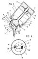
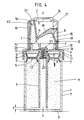
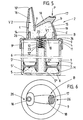
- the dispenser for dispensing paste-like mass M in portions comprises a dispenser housing 1 receiving it and a pump device 2.
- the dispenser housing 2 is a glass with a threaded neck 3 that contains, for example, mustard (see FIGS. 1 and 7) or a glass having a bead 4 (see FIG. 4).
- At least the inner wall surface 1 ⁇ of the dispenser housing 1 or the glass is cylindrical in the longitudinal direction and circular in cross section.
- the outer surface 1 ⁇ of the dispenser housing 1 there is designed slightly spherical, that is to say there is an external elliptical cross section in the direction explained, ie the outer dimension of the glass is larger in diameter in the central region than in the two end regions.
- the pump device 2 which can be assigned to the glasses by means of corresponding counter-holding means, has a piston 5. Its lip 5 ⁇ or lip 5 ⁇ , which tips out towards the free end, leads to the cylindrical inner wall surface 1 ⁇ of the dispenser housing 1.
- the piston sits on the outer surface of a riser tube 6 with a circular cross section stationary and extends in the longitudinal center axis xx of the cylindrical dispenser housing 1.
- the corresponding central opening of the piston 5 is designated by 7. It also forms lips 5 ⁇ in the area of the opening, which rest sealingly on the lateral surface of the riser pipe and wipe off the mass cleanly.
- the system pressure is such that there is a frictional allocation or management.
- the piston 5 is further made of elastic material. It is plate-shaped. Its thickness in the central ring area is chosen to be larger than the periphery forming one or more ring lips. Projected into the plane, the diameter of the piston 5 is larger than the largest clear diameter of the Dispenser housing 1. In all cases, the piston has a rounded edge facing away from the direction of assignment z (see FIG. 1) or a bend (see FIG. 7). There the edge portion of the piston 5 passes over a V-shaped groove 5k into the central, thick-walled piston ring surface. The peripheral V-leg is longer than the other V-leg. Its length corresponds to half of the former; the divergence angle is approximately 90 degrees. The mass-side projection of the V-apex Sch is essentially flush with the lip end of the inner wiper lip 5 ⁇ leading on the outer surface of the riser pipe.
- the riser pipe 6 ends at a short distance y from the bottom 8 of the dispenser housing 1. The distance is clearly below the clear diameter dimension of the riser pipe. This and the high degree of elasticity of deflection of the piston 5 leads to an almost completely free discharge of the pasty mass M.
- the plate shape shown in FIG. 7 (the apex Sch corresponds to the ring standing edge of the plate) could also optimize the residual output, at least in the central region of the plate 7, slight retraction of the floor can be adapted.
- the riser is also cut obliquely on the bottom. The highest point is on the floor at 8.
- the riser pipe 6 sits below a cover 10 which closes the opening of the cup-like dispenser housing and at the same time has the fastening means for the pump device 2.
- the cover 10 is formed by an attachment 9 realized as a screw cover. Be Internal thread interacts with the corresponding external thread of the neck 3.
- the ceiling 10 is realized from the bottom of an attachment 9 designed as a clip cap.
- the clip cap has in the vicinity of the ceiling 10 in the essentially parallel to the housing wall 9 ⁇ a clip groove 11, which cooperates with the section of the dispenser housing also projecting section of the bead rim 4, which thus acts transversely outwardly projecting section as a clip projection.
- the inside of the ceiling is funnel-shaped. Both types of assignment described are therefore reversible.
- the attachment 9 thus functioning as an adapter merges according to FIG. 7 via an intermediate stage St into an attachment ring 9 ⁇ which is larger in cross section than the attachment wall 9 ⁇ .
- Whose outer surface can be roughened or grooved to increase the grip.
- the inside of the cross-sectional attachment ring 9 ⁇ carries the counter thread for the neck-side thread. It lies with its outer surface level with the outer surface of the dispenser housing 1.
- the correspondingly conforming arrangement results from the neck-forming inward displacement of the wall of the dispenser housing (this applies to FIG. 1).
- the realized as a horizontal wall offset intermediate stage St extends above the upper edge 3 ⁇ of the dispenser housing neck 3.
- the relevant zone can therefore be used in an advantageous manner to form sealing measures, which consist in that of the bottom of the intermediate stage St an inclined sealing lip 9 ⁇ goes out.
- the riser pipe 6 To connect the riser pipe 6 to the attachment 9, the latter forms a socket-like insertion sleeve 12 which is open towards the interior of the dispenser housing 1.
- the plug connection is preferably frictional.
- the insertion sleeve 12 brings a widening of the riser pipe. This widening is used for the distance-defining assignment of the piston 5, namely in its initial basic position.
- the ceiling-side widening of section 13 of the riser pipe 6, which is widened from the foot section of a funnel-shaped section, is realized. On the ceiling side, it corresponds to three to four times the inside diameter of the riser pipe.
- the section 13 still extends within the neck zone of the dispenser housing 1.
- the funnel-shaped section 13 then merges upwards into a cylindrical one. This creates a kind of prechamber.
- the piston 5 itself is also included in the distance-forming measure in that it has a collar K projecting over its peripheral sealing edge in the direction of the ceiling 10.
- the latter partially overlaps the insertion sleeve 12.
- the cylindrical insertion sleeve 12 forms a stepped projection which enters a corresponding ring recess at the corresponding end of the collar K, so that an S-joint is formed. Both parts can thus enter into a connection that corresponds to friction.
- a snap connection is also conceivable.
- the variant shown in FIG. 11 forms an annular clamping bead 5 ⁇ in the end region of the collar K on the ceiling. The latter can be take into account in the way of the molding.
- the inside is funneled on the ceiling side of the bead and cut back on the inside, so that practically only the crest of the clamping bead 5 ⁇ and the wiping lip 5 ⁇ formed on the other end of the collar K come into leading contact with the outer wall of the riser tube 6.
- Cross-slitting of the region of the collar K forming the clamping bead 5 ⁇ , in combination with the funnel there, facilitates “threading” of the piston onto the riser pipe.
- the collar K extends in the same axial overhang on both sides of the piston ring surface.
- the riser tube 6 is not inserted into the insertion sleeve 12, but rather onto the latter.
- a cylindrical plug-in projection 14 of the attachment 9 for a bellows B, which extends concentrically to the insertion sleeve 12.
- the latter is made of rubber or correspondingly elastic or flexible plastic and, after approval, always takes the one from FIGS. 1, 4 and 7 apparent basic position again; the restoring force is measured accordingly.
- this bellows forms the headpiece of the dispenser.
- the interior of the bellows forms a pump chamber 15 in conjunction with the ceiling 10.
- the plug-in projection is formed by the pot wall of the attachment 9.
- the head piece is sealingly bumped onto it.
- the section of the bellows B or head piece comprising the largest proportion of space is connected to an outlet nozzle 16.
- An actuating surface 17 is located adjacent to the decentralized dispensing nozzle 16 near the edge. This is roughened or corrugated to increase the grip and continues into a wall section 18 falling towards the inner end of the tube. The thickness of the same decreases in this direction either continuously (see FIG. 5) or abruptly (see FIG.
- a second kink is located below the zone of the actuating surface 17 of the wall section 18 which has the maximum wall thickness. From there, the wall section 18 continues into a foot wall 19 which slopes more steeply in the opposite direction and which is rooted in the plug-in projection 14 of the head piece. Wall section 18 and foot wall 19 act like a toggle lever.
- the included angle carries about 90 degrees in the basic position ( Figures 1.4). When pressed, this angle increases continuously up to the extended position.
- the dispensing spout 16 On the outer flank opposite the dispensing spout 16 of the actuation button 17, the dispensing spout 16 forms a bending point c slightly below the height of the kink a.
- a last kink d is taken into account at the lower end of the foot wall 19, and indeed at the level of the upper end of the plug-in projection 14. All of the kinks together bring together a polygon which, when loaded on the actuating surface 17, brings the folding position shown in FIG. 2, for example, which leads to a slight radial outward pivoting of the dispensing spout 16.
- said kink c is defined by a wall-side wall gap, the open end of which points in the direction of the ceiling 10.
- the pump chamber 15 also has an inlet valve V1 on the housing side and an outlet valve V2 on the nozzle side.
- the inlet valve V1 is implemented as a folding valve, this by cutting a flap 20 out of the ceiling 10 of the plug-in projection 14 of the attachment 9 made of correspondingly flexible material.
- the thickness of the remaining connection zone to the plug-in projection 14 is significantly reduced, so that a lateral film hinge 21 is present.
- the tab 20 lies on the side opposite the film hinge 21 on the cut edge of the hole forming a valve seat, in addition the film hinge lies in the region of the upper side of the plug-in projection 14, so that a passage in the opposite direction, i.e. edge system is prevented in the direction of the riser pipe 6.
- the third exemplary embodiment is an input valve V1 of the same design.
- the only difference is a dome-shaped curvature of the valve flap 20 there.
- this basically bowl-shaped flap is held in the base region in the plane of the ceiling 10.
- the shell cavity points towards the interior of the riser pipe.
- the support here takes place on the ceiling-side end edge of the riser pipe 6.
- the entire edge of the cap-shaped valve flap 20 does not lie on it, but only the outer partial area of the end wall. Rather, the inner area is designed in the manner of an annular rib, with an outer conical surface which bears against the inner edge of the cylindrical tube.
- the outlet valve V2 on which the first two exemplary embodiments are based deviates from the classic design. There, the outlet valve is practically formed by the paste-like mass itself, which behaves like a frictional "plug", which is displaced more slowly than under vacuum in the pump chamber 15 due to the corresponding cross-sectional dimensioning of the tube than the mass feeding the pump chamber supply.
- the same configuration is present with regard to the dispensing spout 16; only the input valve V1 is of a slightly different design. It is a centrally perforated ceiling 10 of the attachment 9 overlapping plates. The resilient contact on its corresponding valve seat surface is effected by a tension coil spring 23. Their upper terminal spring turn can be molded onto the plate 22 in the same way. The helix passes through the insertion sleeve 12 over its entire length, in order finally to be supported on the end face 12 'of the insertion sleeve 12 there with the lower terminal winding having a larger helix diameter.
- the outlet valve V2 is again designed as a valve flap 20. This is in the attachment area of the dispensing spout 16. It arises from a hinge 16 ⁇ -forming, cutting-like projection.
- the corresponding valve seat surface of the valve flap 20 is formed by the inner wall of the dispensing spout and is simply supported by slightly tilting the valve flap in the dispensing direction.
- the head piece is covered by a protective cap 24.
- Their cap base forms a section course in a rotationally symmetrical manner, which is used in such a way that the mouth edge 16 ⁇ of the dispensing nozzle 16 lies sealingly against the corresponding inner surface 24 ⁇ of this cover cap 24.
- the ceiling-side end region of the protective cap 24 carries on its inside the thread 28, which interacts with a corresponding counter thread 29 of the bellows B or head piece. It is a multi-start steep thread.
- the front end 24 ⁇ of the protective cap 24 is screw-limiting against an outwardly directed annular collar 30 formed in the lower edge region of the attachment 9. Below the annular collar 30, there is also the annular intermediate step St of the attachment 9.
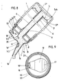
- the annular collar 30 is designed as a movable sealing lip. Reference is made to FIG. 10. As can be seen, the annular collar 30 lifts off the corresponding annular surface of the intermediate stage St when the protective cap 24 is not firmly screwed on. Only when the protective cap 24 is tightened more tightly is the annular collar 30 pressed against said surface. The pasty mass is hermetically sealed.
- annular groove 30 ⁇ formed from above increases the mobility of the annular collar 30; it is aligned with the protective cover wall.
- the holes 26 are realized in the form of transverse bores in the plug-in projection 14.
- the closed position is identified in FIG. 10 by the dash-dotted line type.
- the load-bearing gap bears the reference number 31. It consists of a vertical channel section 32 and a horizontal channel section 33 which adjoins via a slope. The latter is connected to the hole 26.
- the dispenser housing 1 containing the pasty mass M With the pump device 2, the latter is supplied from above via the neck 3.
- the flexibility of the piston strips the inner wall of the housing 1 ⁇ cleanly and without loss.
- the outer edge of the edge portion of the piston 5 which is bent in the direction of the ceiling 10 is then in the initial basic position immediately below the transition stage U between the neck 3 of smaller cross section and the area of the dispenser housing which has a larger inside diameter. In the said basic starting position (compare FIG.
- Pasty mass is drawn in via the riser pipe 6.
- the corresponding effect continues on the mass M surrounding the riser 6 in the manner of a ring, with the consequence that the piston 5 is sucked in via the latter in the direction of the base 8, and this at every dispensing step.
- the output is not against the load on the rest of the material.
- the corresponding reset takes place in a return stroke that is independent of the actuation stroke.
- the space behind the piston 5 experiences a pressure equalization according to holes 26 penetrating the ceiling or the wall of the attachment 9.
- the refilling of the pump chamber 15 is completed in each case before the mass in the dispensing nozzle 16 can suck into the pump chamber. In the third exemplary embodiment, this prevents the outlet valve V2 having a valve flap 20.
- the relatively slight shifting back of the stopper-shaped portion is also advantageous in that any protruding from the dispensing portion is withdrawn via the mouth opening 16ö réelle of the dispensing spout 16 becomes.
- FIGS. 14 and 15 A modified embodiment of the input valve V1 is also illustrated in FIGS. 14 and 15.
- the inlet valve V1 consists of a stamped part made of elastic material.
- the thickness of the starting material is about 1 mm. It can be rubber or a comparable elastic or flexible material.
- the shape of the elastic flap is comparable to that of a sound body, for example a guitar.
- the elastic flap forming the inlet valve V1 is placed with its smaller contour on a support pin 34. The latter is molded onto the cover 10 of the attachment 9 in the same way. It is a cylindrical stud.
- the slip opening of the flap 20 is chosen to be somewhat smaller, so that there is a tensing wrap, which causes a certain rotation lock.
- a further measure of preventing the flap from pivoting on the trunnion is an annular wall 35 surrounding the edge 20 ⁇ of the circular flap 20 with some play.
- the edge 20 ⁇ is cut slightly conically, the taper lies in the direction of the riser pipe 6.
- the ring wall 35 is left open in the direction of the trunnion 34.
- the opening is smaller than the circle round diameter of the flap 20.
- the ends of the annular wall 35 point contactlessly in the direction of a gusset area 37 between the attachment molding and the actual valve body.
- the gussets 37 result from the approximately tangential attachment of two geometrically circular sections of the diecut.
- the height of the annular wall 35 is selected so that it ends at the top with the top of the tab 20.
- the valve seat surface is formed by a cutting-shaped, also upwardly directed annular rib 36.
- the latter starts from the top of the blanket 10 and is molded onto it immediately.
- the cross section of this ring rib 38 is triangular, with one side of the triangle rooted in the top of the ceiling 10.
- the cutting edge is around 30 to 60 degrees.
- the ridge of the ring rib 38 is aligned at the same height with an annular shoulder 39 of the trunnion 34 supporting the tab 20 in the fastening region.
- the annular rib 38 extends approximately in the vertical plane of the insertion sleeve 12 formed on the underside of the ceiling.
Landscapes
- Physics & Mathematics (AREA)
- Fluid Mechanics (AREA)
- General Physics & Mathematics (AREA)
- Closures For Containers (AREA)
- Reciprocating Pumps (AREA)
Applications Claiming Priority (4)
| Application Number | Priority Date | Filing Date | Title |
|---|---|---|---|
| DE8626411U | 1986-10-03 | ||
| DE8626411 | 1986-10-03 | ||
| DE19873716110 DE3716110A1 (de) | 1986-10-03 | 1987-05-14 | Spender fuer portionierten ausgabe pastoeser massen |
| DE3716110 | 1987-05-14 |
Publications (2)
| Publication Number | Publication Date |
|---|---|
| EP0262535A2 true EP0262535A2 (fr) | 1988-04-06 |
| EP0262535A3 EP0262535A3 (fr) | 1989-02-01 |
Family
ID=25855581
Family Applications (1)
| Application Number | Title | Priority Date | Filing Date |
|---|---|---|---|
| EP87113738A Withdrawn EP0262535A3 (fr) | 1986-10-03 | 1987-09-19 | Dispensateur pour la distribution dosée de substances pâteuses |
Country Status (4)
| Country | Link |
|---|---|
| EP (1) | EP0262535A3 (fr) |
| AU (1) | AU7909787A (fr) |
| BR (1) | BR8705251A (fr) |
| DE (1) | DE3716110A1 (fr) |
Cited By (10)
| Publication number | Priority date | Publication date | Assignee | Title |
|---|---|---|---|---|
| FR2635473A1 (fr) * | 1988-08-19 | 1990-02-23 | Oreal | Dispositif pour distribuer des doses d'un produit pateux |
| EP0330928A3 (en) * | 1988-02-29 | 1990-11-14 | Colgate-Palmolive Company | Dispensing device |
| EP0499538A1 (fr) * | 1991-02-13 | 1992-08-19 | S O F A B | Conditionnement de produits semi-consistants |
| WO1993009408A1 (fr) * | 1991-11-08 | 1993-05-13 | Novapharm Research (Australia) Pty Limited | Pompe de distribution a pression |
| EP0782963A1 (fr) * | 1995-12-18 | 1997-07-09 | Guala Dispensing S.P.A. | Distributeur de produits pâteux tels crèmes cosmétiques et similaires |
| US6302304B1 (en) | 1995-09-22 | 2001-10-16 | Rieke Packaging Systems Limited | Dispensing systems |
| GB2367865A (en) * | 2000-03-21 | 2002-04-17 | English Glass Company Ltd | Dispensing system with follower plate |
| WO2013025771A1 (fr) * | 2011-08-15 | 2013-02-21 | The Procter & Gamble Company | Applicateurs cosmétiques |
| WO2018192888A3 (fr) * | 2017-04-19 | 2018-12-13 | Asept International Aktiebolag | Agencement pour dosage d'un fluide |
| CN115057079A (zh) * | 2022-06-01 | 2022-09-16 | 湖南继兴科技有限公司 | 一种具有密封混合功能的双组份环氧树脂包装罐 |
Families Citing this family (2)
| Publication number | Priority date | Publication date | Assignee | Title |
|---|---|---|---|---|
| NL1023670C1 (nl) | 2002-07-03 | 2004-01-06 | Keltub B V | Samenstel van balg en afroldeel, pomp en werkwijze voor het gebruik daarvan. |
| CN103803183B (zh) * | 2014-02-23 | 2016-01-27 | 北京金恒博远冶金技术发展有限公司 | 一种抽压式液体容器 |
Family Cites Families (2)
| Publication number | Priority date | Publication date | Assignee | Title |
|---|---|---|---|---|
| DE3006680A1 (de) * | 1980-02-22 | 1981-08-27 | Hans Schwarzkopf Gmbh, 2000 Hamburg | Behaelter fuer pastoese und fluessige produkte mit einer vorrichtung zum ausbringen nahezu gleicher oder verscheidener volumenmengen und seine verwendung |
| DE3521580A1 (de) * | 1985-02-21 | 1986-08-21 | Bayer Ag, 5090 Leverkusen | Ausgabeeinrichtung fuer fliessfaehige medien |
-
1987
- 1987-05-14 DE DE19873716110 patent/DE3716110A1/de not_active Withdrawn
- 1987-09-19 EP EP87113738A patent/EP0262535A3/fr not_active Withdrawn
- 1987-09-30 AU AU79097/87A patent/AU7909787A/en not_active Abandoned
- 1987-10-02 BR BR8705251A patent/BR8705251A/pt unknown
Cited By (12)
| Publication number | Priority date | Publication date | Assignee | Title |
|---|---|---|---|---|
| EP0330928A3 (en) * | 1988-02-29 | 1990-11-14 | Colgate-Palmolive Company | Dispensing device |
| FR2635473A1 (fr) * | 1988-08-19 | 1990-02-23 | Oreal | Dispositif pour distribuer des doses d'un produit pateux |
| EP0499538A1 (fr) * | 1991-02-13 | 1992-08-19 | S O F A B | Conditionnement de produits semi-consistants |
| WO1993009408A1 (fr) * | 1991-11-08 | 1993-05-13 | Novapharm Research (Australia) Pty Limited | Pompe de distribution a pression |
| US6302304B1 (en) | 1995-09-22 | 2001-10-16 | Rieke Packaging Systems Limited | Dispensing systems |
| EP0782963A1 (fr) * | 1995-12-18 | 1997-07-09 | Guala Dispensing S.P.A. | Distributeur de produits pâteux tels crèmes cosmétiques et similaires |
| GB2367865A (en) * | 2000-03-21 | 2002-04-17 | English Glass Company Ltd | Dispensing system with follower plate |
| WO2013025771A1 (fr) * | 2011-08-15 | 2013-02-21 | The Procter & Gamble Company | Applicateurs cosmétiques |
| US9167880B2 (en) | 2011-08-15 | 2015-10-27 | The Procter & Gamble Company | Cosmetic applicators |
| EP2744365B1 (fr) * | 2011-08-15 | 2021-12-08 | Noxell Corporation | Appareil cosmétique |
| WO2018192888A3 (fr) * | 2017-04-19 | 2018-12-13 | Asept International Aktiebolag | Agencement pour dosage d'un fluide |
| CN115057079A (zh) * | 2022-06-01 | 2022-09-16 | 湖南继兴科技有限公司 | 一种具有密封混合功能的双组份环氧树脂包装罐 |
Also Published As
| Publication number | Publication date |
|---|---|
| EP0262535A3 (fr) | 1989-02-01 |
| AU7909787A (en) | 1988-04-14 |
| DE3716110A1 (de) | 1988-04-14 |
| BR8705251A (pt) | 1988-05-24 |
Similar Documents
| Publication | Publication Date | Title |
|---|---|---|
| EP0144879B1 (fr) | Distributeur pour matériaux pâteux, notamment distributeur de pâtes dentifrices | |
| EP0036491B1 (fr) | Distributeur pour produits pâteux | |
| EP0230252B2 (fr) | Distributeur pour produits pâteux | |
| DE2623964C3 (de) | Drucktasten-Sprüheinrichtung | |
| EP0312722B1 (fr) | Pompe de dosage et d'atomisation pour matières liquides ou visqueuses | |
| DE69517058T2 (de) | Spender für Flüssigkeiten | |
| EP0316759B1 (fr) | Distributeur pour produits pâteux | |
| DE3033392A1 (de) | Vorrichtung zur ausgabe von pasteusen oder breiigen medien | |
| DE3928524A1 (de) | Spender | |
| DE3716110A1 (de) | Spender fuer portionierten ausgabe pastoeser massen | |
| DE8713197U1 (de) | Spender zur portionierten Ausgabe pastöser Massen | |
| EP0226777A2 (fr) | Distributeur pour matières pâteuses | |
| EP0394750A2 (fr) | Pompe de dosage pour bouteilles ou autres récipients | |
| EP0179342A2 (fr) | Distributeur pour produits pâteux | |
| EP0250965A1 (fr) | Distributeur | |
| DE69415663T2 (de) | Verschluss mit einer zweiteiligen verschiebbaren spenderkappe | |
| EP0376097A2 (fr) | Distributeur-doseur d'un produit pâteux | |
| EP0385077A2 (fr) | Dispositif pour la pulvérisation d'un fluide à usage médical, cosmétique ou similaire | |
| EP0282791B1 (fr) | Distributeur pour produits pâteux | |
| EP1344570B1 (fr) | Distributeur des produits fluides | |
| EP3953053B1 (fr) | Distributeur de produits pâteux | |
| DE3343680A1 (de) | Spender fuer pastoese massen, insbesondere zahncremespender | |
| EP1170062B1 (fr) | Pompe de distribution | |
| DE3214868A1 (de) | Spendebehaelter zur portionsweisen abgabe eines insbesondere pastoesen gutes, wie z.b. zahncreme | |
| EP0221362B1 (fr) | Distributeur pour produits pâteux |
Legal Events
| Date | Code | Title | Description |
|---|---|---|---|
| PUAI | Public reference made under article 153(3) epc to a published international application that has entered the european phase |
Free format text: ORIGINAL CODE: 0009012 |
|
| AK | Designated contracting states |
Kind code of ref document: A2 Designated state(s): AT BE CH DE ES FR GB GR IT LI LU NL SE |
|
| PUAL | Search report despatched |
Free format text: ORIGINAL CODE: 0009013 |
|
| AK | Designated contracting states |
Kind code of ref document: A3 Designated state(s): AT BE CH DE ES FR GB GR IT LI LU NL SE |
|
| STAA | Information on the status of an ep patent application or granted ep patent |
Free format text: STATUS: THE APPLICATION IS DEEMED TO BE WITHDRAWN |
|
| 18D | Application deemed to be withdrawn |
Effective date: 19890802 |
|
| RIN1 | Information on inventor provided before grant (corrected) |
Inventor name: RAUEN, KARL ALBERT Inventor name: METTENBRINK, HERBERT |