EP0262590A2 - Trennungsgerät und -verfahren von Kurzwellen- und Langwellensignalen - Google Patents
Trennungsgerät und -verfahren von Kurzwellen- und Langwellensignalen Download PDFInfo
- Publication number
- EP0262590A2 EP0262590A2 EP87113976A EP87113976A EP0262590A2 EP 0262590 A2 EP0262590 A2 EP 0262590A2 EP 87113976 A EP87113976 A EP 87113976A EP 87113976 A EP87113976 A EP 87113976A EP 0262590 A2 EP0262590 A2 EP 0262590A2
- Authority
- EP
- European Patent Office
- Prior art keywords
- wavelength
- short
- long
- passageway
- aperture
- Prior art date
- Legal status (The legal status is an assumption and is not a legal conclusion. Google has not performed a legal analysis and makes no representation as to the accuracy of the status listed.)
- Withdrawn
Links
Images


Classifications
-
- H—ELECTRICITY
- H01—ELECTRIC ELEMENTS
- H01P—WAVEGUIDES; RESONATORS, LINES, OR OTHER DEVICES OF THE WAVEGUIDE TYPE
- H01P1/00—Auxiliary devices
- H01P1/20—Frequency-selective devices, e.g. filters
- H01P1/213—Frequency-selective devices, e.g. filters combining or separating two or more different frequencies
- H01P1/2138—Frequency-selective devices, e.g. filters combining or separating two or more different frequencies using hollow waveguide filters
-
- H—ELECTRICITY
- H01—ELECTRIC ELEMENTS
- H01Q—ANTENNAS, i.e. RADIO AERIALS
- H01Q5/00—Arrangements for simultaneous operation of antennas on two or more different wavebands, e.g. dual-band or multi-band arrangements
- H01Q5/40—Imbricated or interleaved structures; Combined or electromagnetically coupled arrangements, e.g. comprising two or more non-connected fed radiating elements
- H01Q5/45—Imbricated or interleaved structures; Combined or electromagnetically coupled arrangements, e.g. comprising two or more non-connected fed radiating elements using two or more feeds in association with a common reflecting, diffracting or refracting device
Definitions
- the present invention relates to signal separation, and more particularly, to a method and device for separating into distinct paths a long-wavelength signal and a short-wavelength signal having a common area of focus.
- a signal separator is needed for a dual-mode sensor which senses radiation in the microwave or millimeter wave frequency range, and as a second mode, senses radiation also in the infrared, visible, or ultraviolet range.
- a signal separator is required if the dual mode system is a so-called "common-optics" system; that is, one in which the two sensing wavelengths use the same antenna system, and bring both radiation beams to the same point of focus.
- Such common-optics dual-mode sensors are desirable in that the two beams are viewing the same point on an object at the same time, thus making it easier for the signal processor to ascertain the nature of the object being viewed.
- a circulator or transmit-receive device is added to the radar wavelength channel of the signal separator, the device becomes a dual-waveband duplexer, which permits both transmission and reception of the radar wavelength in the long-wavelength path.
- One category of presently known signal separators include devices, such as channelizing filters, which split the combined signal into two or more waveguides, and then in each waveguide filter out all signals not of the desired wavelength. Such power splitting, and then filtering, though, tends to severely lower the signal strength; therefore, such devices are unable to be used in applications having low signal power. Also, devices of this type do not appear to be practical when the wavelength bands of interest are as widely separated as the microwave and visible wavelength bands.
- Another category of signal separators utilizes screens, optical filters, or dichroic filters to achieve power splitting and filtering.
- the devices employed are selected to reflect certain wavelengths and allow others to pass.
- this category of separator can handle wavebands which are widely separated in wavelength.
- media filter/screen combinations tend to be inefficient in that the radiation in one or the other of the two bands is severely attenuated after passing through or reflecting off of such filter/screen combinations.
- Microwave antennas which reflect infrared radiation, such as might arise from a nuclear blast, while continuing to bring a microwave signal to a focus are also known. Although such deflecting devices are efficient at both the microwave and infrared wavelengths when compared to the media filter/screen devices, they are designed for applications in which the infrared radiation is not a signal. Thus, such antennas do not channel or direct the infrared onto a deflector where it could be processed as a signal in the same manner as the microwave or millimeter wavebands.
- a device for channeling into separate paths a long-wavelength signal and a short-wavelength signal, the short-wavelength signal being in the form of a ray cone comprising: means for collecting the short and long-wavelength signals at a common area of focus, the short-wavelength being in the form of a ray cone having a central axis extending in a first direction; waveguide means for propagating the long-wavelength in a second direction extending at an angle to the first direction; means for passing both the short and long-wavelength signals in the first direction into the waveguide means; means for deflecting the long-wavelength signal to propagate through the waveguide means in the second direction, while passing the ray cone in the first direction to converge at a point along the central axis external of the waveguide means; and means for detecting the short-wavelength signal substantially at the point of convergence.
- a method of channeling a short-wavelength signal and a long wavelength signal into separate paths, the short-wavelength signal being in the form of a ray cone comprising, collecting the long- and short-wavelength signals at a common area of focus; passing the collected signals in a first direction along a central axis into and then out of a waveguide passageway; deflecting the long-wavelength signal through the waveguide in a second direction at an angle to the first direction; passing the short-wavelength signal through an aperture aligned with the central axis, the aperture having a diameter sufficient to passes the short-wavelength ray cone while effectively blocking the long-wavelength deflected signal; and detecting the short-wavelength signal for processing.
- the method of separating short-wavelength signals and long-wavelength signals into separate paths comprises collecting the combined signals at a common focus area; passing both signals in a first direction along a central axis into the interior of a waveguide; deflecting the long-wavelength signal through the wavelength in a second direction at an angle to the first direction; and passing the short wave signal in the first direction through an exit aperture aligned with the central axis and dimensioned to effectively block the long-wavelength signal, for converging the short-wavelength signal at a point exterior of said waveguide; and detecting the short-wavelength signal substantially at the point of convergence.
- Means are provided for passing both the short-wavelength and long-wavelength signals in said first direction into the waveguide means, together with means for deflecting the long-wavelength signal to propagate through the waveguide means in the second direction while passing the ray cone in the first direction to converge at a point external of the waveguide means, and means for sensing the short-wavelength signal substantially at the point of convergence.
- the device of the present invention comprises a housing having an exterior surface; and a waveguide means in the housing having an input/output port and having a first and second pair of spaced opposing internal surfaces defining a passageway extending along a propagation axis in one direction for propagating the long-wavelength signal along a portion of a path extending in the one direction to the input/output port.
- the housing in a first portion thereof has a first aperture means located in one of the first pair of internal surfaces and having a selected dimension greater than the width of the passageway.
- the housing in a second portion thereof has a second aperture means in the other of the first pair of internal surfaces of the passageway coaxial with the first aperture means.
- Collecting means having an outer end and a throat end, and tapered at a selected angle to have a cross-sectional area at the throat end smaller than the cross-sectional area at the outer end, is attached to the exterior surface of the housing adjacent the throat end and surrounds the first aperture means for directing the long-wavelength signal into the first portion of the passageway.
- the collecting means has a central axis extending in another direction at an angle to the one direction coaxial with the first and second aperture means; and permits the passage of the short-wavelength signal in the form of a ray cone having a point of convergence on the central axis a selected distance from the throat.
- the second aperture means has a diameter large enough to pass the short-wavelength ray cone to the point of convergence while effectively blocking the long wavelength signal for deflection along the propagation axis in the one direction.
- a short wavelength sensing means is disposed substantially at the point of ray convergence for detecting the short-wavelength signal for processing.
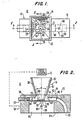
- long-wavelength and short-wavelength signal separator is shown in Figs. 1 through 5 inclusive, and is represented generally by the numeral 10.
- long wavelength is meant to include frequencies from the UHF region through the submillimeter region; that is, from 300 MHz to 3000 GHz
- a short-wavelength signal as used herein means the infrared, visible, ultra violet and higher frequency regimes.
- the short-wavelength signal may be formed into a ray cone by an antenna or optical system, for example, that works in conjunction with the separator of the present invention.
- the actual ray cone angle is determined by such optical system or antenna.
- the angle ⁇ shown in Figs. 2 and 3 represents the maximum allowable ray cone angle that can pass to the short-wavelength detector without obstruction.
- the signal separator of the present invention includes means for collecting the short-wavelength and long-wavelength signals at a common focal area and accommodating without blockage the short-wavelength signal having a predetermined maximum ray cone angle.
- the collecting means for the short and long-wavelength signals includes a housing 12 a focus system 13 and a feedhorn 14 projecting from an external surface 16 of the housing.
- Focus system 13 may be any conventional type system that collects and forms a short-wavelength signal into a ray one, such as a cassegrain antenna or optical focusing system, for example.
- Such system is of the type that is fixed relative to housing 12 to focus the short-wavelength radiation to a point, and is able to form a ray cone angle between approximately 11 and approximately 21 degrees, for example.
- Feedhorn 14 which collects the long-wavelength signal and passes the short-wavelength ray cone has a first pair of sidewalls 22 and 24, respectively. Sidewalls 18, 20, 22, and 24 define a pyramidal configuration that is substantially rectangular in cross-section.
- feedhorn 14 is tapered to have a cross-sectional area at throat end 26 that is smaller than the cross-sectional area of an outer end 28.
- Feedhorn 14 may be fastened to housing 12 by conventional means such as welding, brazing, or bolting (not shown), or it may even be cast integral with the housing, for example.
- horn 14 was tapered such that sidewalls 18 and 20 each formed an angle of approximately 11.9 degrees relative to central axis 21, or 23.8 degrees relative to each other and sidewalls 22 and 24 formed an angle of 37.2 degrees relative to each other.
- Sidewalls 18 and 20 terminate at edge 30 and 32 defining throat end 26 while sidewalls 22 and 24 terminate at lower edges 31 and 33, respectively.
- Bevels 34 and 36 essentially extend feedhorn walls 22 and 24 into passageway 50.
- the area of the waveguide means 40 below throat 26 constitutes a waveguide feed region which together with the horn 14 provide the throat field orientation necessary to launch the long-wavelength signal.
- waveguide means referred to at 40 has a first pair of spaces opposing internal surfaces 42 and 44 (Fig. 2); and a second pair of opposing internal surfaces 46 and 48 (Fig. 3) defining a passageway 50 that is substantially rectangular in cross-section and extends linearly in a first direction for a portion of its length substantially parallel to external surface 16 of the housing.
- Passageway 50 curves at approximately a 90 degree angle to communicate at open end 52 in external surface 54, which is opposite external surface 16 of housing 12.
- a conventional shorting plunger 57 such a a non-contacting type, for example, is included in passageway 50 through an open end of the passageway opening at external surface 58 of the housing.
- Passageway 50 of waveguide means 40 is dimensioned for propagating and guiding a long-wavelength signal as defined herein.
- Passageway 50 is dimensioned such that the width of the waveguide means or the broad dimension as defined by the width of inner surfaces 42 and 44 is in excess of one-half of the wave-length in free space of the signal to be propagated.
- the height of the passageway 50 or the short dimension as represented by the width of internal surfaces 46 and 48 may be the standard for waveguide passageways, which typically is approximately one-half the broad dimension.
- internal surfaces 42 and 44 have a width dimension, which is commonly referred to as the "a" wall dimension represented by arrows 60 (Fig. 1) of 0.100 inches.
- This same passageway 50 has a height dimension commonly referred to as the "b ⁇ wall dimension represented by arrows 62 (Fig. 2), that is one-half of the width 60 or 0.050 inches.
- the means for passing both the long-wavelength and short-wavelength signals into the portion of passageway 50 below the feedhorn throat 20 includes an aperture means 64 in housing 12 at internal surface 42 of the waveguide means 40. With respect to the long-wavelength signal, this aperture 64 provides communication between the interior of feedhorn 14 and passageway 50 as hereinafter described. With respect to the short-wavelength signal, aperture 64 provides for through passage of the ray cone enroute to aperture 76 and the point of convergence as hereinafter described.
- First aperture means 64 (see Fig. 5) is preferably rectangular in configuration and is dimensioned to correspond to the dimensions of throat 26 of feedhorn 14. Throat 26 is the internal dimension of the feedhorn that is defined as the internal width of sidewalls 22 and 24 of feedhorn 14 (see Figs. 1 and 4) referred to as 31 and 33, respectively, and the width of sidewalls 18 and 20 at edges 30 and 32.
- throat 26 which forms aperture 64 has a substantially larger cross sectional areas than the cross sectional area of passageway 50 of the waveguide means 40.
- the dimensions 65 and 66 of aperture 64 are larger then the "a" wall dimension between inner surfaces 46 and 48 of the waveguide represented by arrow 60. Since the dimensions 65 and 66 are functions of the width of the passageway 50 of the waveguide, these dimensions will vary in various devices in accordance with the wavelength of concern.
- the dimensions 65 and 66 of throat 26 of the feedhorn 14 are in the neighborhood of 40 percent larger than broadwall dimension 60 of passageway 50.
- the throat of the feedhorn 14, or in other words, the dimensions 65 and 66 of the aperture means are each approximately 0.140 inches; and, as previously mentioned, dimension 60 of passageway 50 is 0.10 inches.
- a transition comprised of bevels 34, 36, 74 and 75.
- Bevels 34 and 36 extend down into passageway 50 a selected distance; thus effectively extending feedhorn sides 22 and 24.
- Reverse bevels 74 and 75 extend transverse to channel 50, and slant at an approximate 45-degree angle relative to top surface 16 in Fig. 2.
- tapers 34 and 36 are carved into internal surfaces 46 and 48 to effectively extend feedhorn sidewalls 22 and 24. Since throat width 65 in the embodiment of Figs.
- throat size 65 which is substantially larger than the broadwall dimension of passageway 50, is preferably blended into passageway 50 by continuing the pyramidal taper of the feedhorn 14 on opposite sides 22 and 24.
- reverse bevels or tapers 74 and 75 serve to transition sidewalls 18 and 20 into passageway 50.
- the present invention further includes means for deflecting the long-wavelength signal causing it to propagate through the channel of waveguide means in a second direction extending at an angle to the direction from which both signals enter throat 26 of feedhorn 14.
- the deflection of the long-wavelength signal into the waveguide means is accomplished while permitting the converging of the ray cone of the short-wavelength signal in the first direction at a point external of and at a selected distance from the waveguide means.
- the means for deflecting and permitting the converging include second aperture means 76 in wall 78 of housing 12.
- Aperture 76 and throat 64 of feedhorn 14 are coaxial with central axis 21 of feedhorn 14. (See Figs. 2 and 3).
- Central axis 21 is substantially perpendicular to the plane of internal surface 42 and 44 throughout the linear portion of passageway 50.
- Housing 12 has a chamber 82 formed in external surface 54 that has a depth to render wall 78 as thin as is feasible. In the reduction to practice herein described, such wall 78 is 0.010 inches thick to provide a thin iris aperture 76.
- the diameter of aperture 76 is made large enough to accommodate the desired ray cone angle ⁇ . In so doing, however, it must be kept small enough to minimize coupling of the long-wavelength signal out a passageway 50.
- aperture 76 of sufficient size to achieve the desired ray cone accommodation angle ⁇ , while at the same time restricting long-wavelength power leakage levels through aperture 76 to more than a few percent.
- a conventional sensing device 84 is mounted in chamber 82 in axial alignment with aperture 76 substantially at the point of convergence of the ray cone.
- Detector 84 allows short-wavelength signals to be processed in many well-known ways by a conventional signal processing apparatus 86 (Fig. 6).
- Detector element 84 is typically contained in a small canister housing, which is either evacuated or filled with an inert gas.
- the top of the detector canister which may be a well known TO-8 can has a window through which the incoming rays must pass to impinge on element 84.
- aperture means 76 With respect to aperture means 76, the larger the diameter, the greater the potential for increased leakage of the microwave or millimeter wave signal out of channel 50.
- a device for separating short-wavelength and long-wavelength signals has been constructed to accommodate ray cone angles to over 21 degrees.
- the device experienced only a 2.3 percent loss of radar power due to leakage through aperture 76.
- the diameter of the circular aperture 76 is selected to be no large than necessary to accommodate the short-wavelength ray cone.
- a device generally referred to as 100 is similar to the signal separator 10 previously described, with the exception of embellishments that may be utilized to correct the radiated beam squint and to broaden the tuning bandwidth.
- Device 100 that separates the short-wavelength signal and directs it to detector 84 for subsequent processing in a conventional manner by an apparatus referred to as 86 is similarly constructed and operates in a manner similar to the device described in connection with Figs. 1 through 5.
- a feedhorn 102 is illustrated that is integral with a housing similar to housing 12 in Figs. 1 through 5.
- Feedhorn 102 has sidewalls 104 and 106 that are configured to have internal surfaces 108 and 110, which together with adjacent sidewalls and internal surfaces form a feedhorn having similar angles and dimensions as that described in connection with Figs. 1 through 5. Walls such as 104 and 106 of feedhorn 102 are made thicker in order to accommodate corrugations 114 formed in surface 110 of the feedhorn and can be formed integral with housing such as 12. Additionally, a conventional tuning screw 116 is threadably inserted in an orifice 118 formed in the housing such that projection 120 of turning screw 116 may be adjusted inwardly and outwardly of passageway 50. Because the present invention is a reciprocal device, a conventional transmit/receive apparatus may be connected in a conventional manner to effectively receive and transmit a signal in the long-wavelength or radar frequency (for example) through channel 50 of waveguide means 40.
- the following description of operation is confined to the long-wavelength signal.
- the signal separator is not only reciprocal, but is also nearly lossless. In the microwave bands, this means that the tuning and power transfer properties of the device follow closely the properties of an ideal lossless microwave network.
- power transfer through the device 10 or 100, as the case may be, is maximized by adjusting tuning elements 57 and 116. Maximum power transfer in this case means maximum power indicated out of the feedhorn into space.
- the tuning element 57 is a shorting plunger which electrically shortcircuits the waveguide at inside face 126. A conventional noncontacting variety of plunger 57 is illustrated.
- tuning screw 116 serves as a useful adjunct to mimimize the reflected power 128 at a setting of the plunger 57 which simultaneously minimizes beam squint.
- the existence of the extra tuning element 16 permits tuning the device for broader operation bandwidths.
- the geometrical symmetry of the throat region 64 of feedhorn 102 is such that the reflected wave indicated by dashed arrows behaves the same as the incident wave, represented by solid arrows, except in the opposite direction. In particular, some of the reflected wave turns up into the feedhorn 102, while the remainder goes into the passageway 50 as a contribution to the reflected wave 128 back at the input.
- Feedhorn throat region 64 is not small in wavelengths, and because of that, a wave does not maintain the same phase in traversing the region. Nevertheless, at any particular location, the phase of the reflected wave with respect to the incident wave is adjustable by moving the shorting plunger 57.
- the relative phases of the two waves as represented by solid and dashed arrows in Fig. 6, are assumed to be set as indicated by the arrowheads.
- the feeding arrangement for an individual wave is markedly asymmetrical.
- the wave travels through pasageway 50 and turns a rather sharp corner adjacent to the throat 64 to travel in a direction substantially perpendicular to the passageway 50 to travel up into feedhorn 102.
- the field lines in the feedhorn are not segments of circles, but instead are distorted in such a manner that the average slope of the lines in extending from one side of the horn to the other is not zero.
- the field lines have a residual net tilt. Since these lines also represent the phase fronts, the radiated beam itself is tilted, or squinted.
- the beam due to the indicent wave (solid arrows) squints to the left as viewed in the drawing of Fig. 6, while the beam due to the reflected wave (dashed arrows) squints to the right as viewed in Fig. 6.
- the net beam is a superposition of the two contributing beams, and has a squint somewhere in between.
- the beam squint will be minimized; that is, the radidated beam will be more nearly on the geometrical boresight, or central axis 21 as shown in Figs. 2 and 3, when shorting plunger 57 is adjusted to phase the fields as depicted in Fig. 6.
- plunger 57 is set to reverse the phase of the reflected fields from that shown in Fig. 6, the beam squint will maximize.
- the device of the actual reduction to practice has shown the beam squint to be small, and hence a relatively minor problem.
- the squint exists as a side effect from utilizing a very compact feedhorn feeding arrangement in accordance with the present invention.
- Such a feeding arrangement is employed because it permits short wavelength detector 84 to be moved close to feedhorn throat 64, thus, permitting wider angle ray cones for the short-wavelength separation.
- a squint angle varied from about 2.5 to 7.0 degrees to the left, as viewed in Fig. 2, depending on the adjustment of shorting plunger 57. In most applications, a squint no greater than a few degrees may be compensated by simply tilting the feedhorn.
- corrugations such as 114 may be cut in surface 110 of the feedhorn to speed up the phase velocity at that surface. Speeding up the wave on the left, as viewed in Fig. 6, straightens the beam. The amount of speed up is adjusted by the depth of slots 114, with the optimum depth being somewhat greater than one quarter of a free-space wavelength at the lowest microwave frequency in the operating band. As is well known, slots such as 114 must reflect a capacitive resistance at their openings in order to increase the phase velocity of the wave over the slotted surface.
- the invention includes a signal separator embodiment having waveguide means that has a passageway that is widened for a selected distance along its length to form a symmetrical cavity that extends outwardly from both sides of the narrower uniform portion of the waveguide passageway.
- a signal separator generally referred to as 140 includes a waveguide means 142 formed in housing 144, and has a shorting plunger 146 adjustably disposed in passageway 148 of the waveguide means 142.
- Passageway 148 has a broadwell dimension that exceeds one-half of the wavelength of concern in free space, similar to the previously described embodiments.
- passageway 148 has an inner surface that extends outwardly on both sides of second aperture means 150 to form a general octagonal surface bounded by sidewall planar surfaces 154, 156, 158, 160, 162 and 164 to form a cavity portion of the waveguide means 142 surrounding second aperture means 150.
- a sleeve 172 which extends into the waveguide means as much as approximately one-third the height or narrow wall dimension of cavity 165.
- a plurality of short-wavelength detectors such as 174 are mounted in the housing and disposed outside of the waveguide means to receive a short-wavelength ray cone through aperture means 150.
- Opposing internal surfaces 166 and 168 extend from cavity portion 165 to provide the normal passageway 148 for the propagation of the long-wavelength signals.
- Sleeve 172 serves several purposes. It assists in transitioning the waveguide fields from cavity 165 of passageway 148 up into a feedhorn 171. Sleeve 172 provides a better impedance match as seen from the microwave input 52 as shown in Fig. 6; and reduces leakage of long-wavelength power through aperture means 150. Sleeve 172 also inhibits the establishment of higher order waveguide modes which would cause distortion in the radiated microwave beam.
- a rectangular first aperture means 186 Formed in housing 144 for effecting communication between passageway 148 and a collector, such as feedhorn 171, (see Fig. 7) is a rectangular first aperture means 186 that may be substantially square in cross section. This aperture is in fact formed by the throat of feedhorn 171.
- the dimension 188 of cavity 165 between sleeve 172 surrounding aperture 150 and flat internal surface portion 156 is sufficient to propogate the same wavelength as passageway 148, that is, dimension 188 exceeds one-half of a free space wavelength at the microwave operating frequency.
- the dimension between sleeve 172 and flat internal surface portion 162, which is also equal to dimension 188 is sufficient to propagate the same wavelength as passageway 148.
- the throat of feedhorn 171 forms a first aperture 186 that is square or rectangular in configuration and has the same dimension as the throat of feedhorn 171.
- the length and width dimensions are each substantially longer than the width of passageway 148, where the width of passageway 148 is commonly termed the broadwall dimension.
- one dimension of the first aperture corresponds to the length of planar surface portions 156 and 162, while the other dimension corresponds to the distance between 156 and 162.
- the ample cavity width between walls 156 and 162 makes it unnecessary to continue the pyramidal feedhorn taper into walls 156 and 162.
- Figs. 7 and 8 are particularly adapted to systems in which the short-wavelength beam is scanned over large angles; or systems wherein mosaic arrays of detector elements such as 174 are utilized to record scenes, for example.
- a method for channeling short-wavelength signals and long-wavelength signals into separate paths, comprising the step of collecting the long and short-wavelength signals which has been brought to a common point of focus.
- a separator feedhorn may be a part of this common optics dual mode antenna by an antenna or optical system.
- short and long-wavelength signals are collected in a feedhorn such as 14, 102 or 171 and are brougnt to a common point of focus along with the short-wavelength ray cone by virtue of the phase center of feedhorn 14, 102 or 171 and are brought to a common point of focus along with the short-wavelength ray cone by virtue of the phase center of feedhorn 14, 102 or 171 being essentially coincident with the ray cone focal point.
- the method further includes passing the collected signals in a first direction along a central axis into the interior of a waveguide.
- the long-wavelength and short wave signals are directed along central axis 21, throat 64, for example, and into the interior of rectangular passageway 50 or 148.
- the method of the present invention further includes deflecting the long-wavelength signal through the waveguide in a second direction at an angle to the first direction.
- the long-wavelength signal strikes interior surface 44 and propagates through the path of pasageway 50, which in the illustrated embodiments is substantially perpendicular to the central axis 21.
- the long wavelength is shorted by plunger 57 and is deflected upwardly in the direction of the central axis through throat 64 and feedhorn 102.
- the method further includes the step of passing the short wavelength signal through an aperture aligned with the central axis having a diameter sufficient to pass the short-wavelength ray cone while effectively blocking the long-wavelength signal.
- second aperture means 76 is circular in cross section, and is intended to have a diameter which permits the short wavelength signal to pass through aperture means 76 to strike sensor 84 while blocking the long-wavelength signal.
- the step of collecting includes receiving a short-wavelength signal which has been formed by an antenna into a ray cone, with the ray cone having an angle about the central axis which provides a point of convergence of the rays at a selected distance along the axis.
- the geometry of the device apparatus, cavity regions and detector locations permits reception of a ray cone as large as conical angle ⁇ .
- Decector 84 is placed at the point of convergence.
- the method comprises passing the short-wavelength and long-wavelength signal through an aperture having a cross-sectional area greater than the cross-sectional area of the waveguide passageway.
- the short-wavelength signal may have a point of convergence which is much closer to the throat 64 than would otherwise be feasible. Moving the convergence point closer to the horn throat enables a wider cone angle ⁇ to be employed; and hence makes the separator useable with a great variety of optical or antenna designs.
- Employed throat 64 also increases long-wavelength efficienty.
- a graph of the radiation pattern of feedhorn, such as 14, is shown for the actual reduction to practice previously referred to.
- the reduction to practice verified the practicality of the device as described herein with regard to wave efficiencies and verified the electromagnetic influences exerted by the various features of the device.
- the fabricated device is designed to accept incoming short-wavelength ray cones of up to approximately 21.3 degrees and has demonstrated a long-wavelength (radar band) efficiency of approximately 86 percent. In other words, 86 percent of the wave power entering port 52 emerges from the horn 14 or 102 as radiation into space. Of the 14 percent loss, approximately 2.3 percent is due to leakage through the ray cone aperture 76.
- This leakage is essentially the same with or without a packaged short wavelength detector 84 inserted into cavity 82.
- the separator was tuned with shorting plunger 57 to provide an imput voltage standing wave ratio (VSWR) of 1.13 at the frequency at which measurements were taken. Moving the shorting plunger over a span of one-half of a guide wavelength varied the beam squint from approximately 2.5 to 7.0 degrees toward the plunger side of the device.
- VSWR voltage standing wave ratio
- the method and system of the present invenion do not require the use directional couplers, inductive coupling loops, capacitive coupling probes, or dummy loads
- the integration of a coupler or probe into a device of the present invention for the purpose of sampling the microwave signal does not alter the basic operation of the device, and hence, does not depart from the spirit or scope of the invention.
- the introduction of tuning posts, irises, tuning screws, changes in waveguide or feed region cross sectional shapes to introduce tuning or impedance matching effects, and all additions or changes of a similar type do not constitute a departure from the spirit or scope of the invention.
- the present invention cover the modifications and variations of this invention provided they come within the scope of the appended claims and their equivalents.
Landscapes
- Physics & Mathematics (AREA)
- Electromagnetism (AREA)
- Waveguide Aerials (AREA)
- Radar Systems Or Details Thereof (AREA)
- Control Of Motors That Do Not Use Commutators (AREA)
- Photometry And Measurement Of Optical Pulse Characteristics (AREA)
- Geophysics And Detection Of Objects (AREA)
Applications Claiming Priority (2)
| Application Number | Priority Date | Filing Date | Title |
|---|---|---|---|
| US913464 | 1986-09-30 | ||
| US06/913,464 US4760404A (en) | 1986-09-30 | 1986-09-30 | Device and method for separating short-wavelength and long-wavelength signals |
Publications (2)
| Publication Number | Publication Date |
|---|---|
| EP0262590A2 true EP0262590A2 (de) | 1988-04-06 |
| EP0262590A3 EP0262590A3 (de) | 1988-12-14 |
Family
ID=25433293
Family Applications (1)
| Application Number | Title | Priority Date | Filing Date |
|---|---|---|---|
| EP87113976A Withdrawn EP0262590A3 (de) | 1986-09-30 | 1987-09-24 | Trennungsgerät und -verfahren von Kurzwellen- und Langwellensignalen |
Country Status (3)
| Country | Link |
|---|---|
| US (1) | US4760404A (de) |
| EP (1) | EP0262590A3 (de) |
| JP (1) | JPS63277940A (de) |
Cited By (2)
| Publication number | Priority date | Publication date | Assignee | Title |
|---|---|---|---|---|
| GB2245765A (en) * | 1987-07-02 | 1992-01-08 | British Aerospace | Electromagnetic radiation receiver |
| WO2007122413A1 (en) | 2006-04-25 | 2007-11-01 | Thruvision Limited | Feedhorn assembly and method of fabrication thereof |
Families Citing this family (9)
| Publication number | Priority date | Publication date | Assignee | Title |
|---|---|---|---|---|
| US6573808B1 (en) * | 1999-03-12 | 2003-06-03 | Harris Broadband Wireless Access, Inc. | Millimeter wave front end |
| ATE522951T1 (de) * | 2006-05-24 | 2011-09-15 | Wavebender Inc | Integrierte wellenleiterantenne und array |
| US20100214185A1 (en) * | 2006-11-01 | 2010-08-26 | The Regents Of The University Of California | Plastic waveguide-fed horn antenna |
| US20080303739A1 (en) * | 2007-06-07 | 2008-12-11 | Thomas Edward Sharon | Integrated multi-beam antenna receiving system with improved signal distribution |
| WO2010068954A1 (en) * | 2008-12-12 | 2010-06-17 | Wavebender, Inc. | Integrated waveguide cavity antenna and reflector dish |
| JP2013037243A (ja) * | 2011-08-09 | 2013-02-21 | Fujitsu Optical Components Ltd | 光変調器 |
| JP6314732B2 (ja) * | 2014-08-04 | 2018-04-25 | 富士通株式会社 | 無線通信モジュール |
| US12074364B2 (en) | 2021-01-21 | 2024-08-27 | The Boeing Company | Sensor waveguide system for a seeker antenna array |
| CN115184927B (zh) * | 2022-07-25 | 2023-04-07 | 北京众智信安信息技术研究院 | 一种微波无损成像目标检测方法 |
Family Cites Families (17)
| Publication number | Priority date | Publication date | Assignee | Title |
|---|---|---|---|---|
| US2912695A (en) * | 1948-12-31 | 1959-11-10 | Bell Telephone Labor Inc | Corrugated wave guide devices |
| NL166566B (nl) * | 1951-01-12 | Ibm | Plaatsingsmechanisme voor lees- en schrijfkoppen. | |
| US2975380A (en) * | 1957-09-30 | 1961-03-14 | Raytheon Co | Waveguide transducer |
| US3602720A (en) * | 1969-12-03 | 1971-08-31 | Us Army | Radio frequency interference filter for optical instrumentation |
| FR2152464B1 (de) * | 1971-09-16 | 1974-05-31 | Thomson Csf | |
| FR2252662B1 (de) * | 1973-11-28 | 1979-04-06 | Cit Alcatel | |
| US3938159A (en) * | 1974-09-17 | 1976-02-10 | Hughes Aircraft Company | Dual frequency feed horn using notched fins for phase and amplitude control |
| US4168504A (en) * | 1978-01-27 | 1979-09-18 | E-Systems, Inc. | Multimode dual frequency antenna feed horn |
| GB1590320A (en) * | 1978-03-20 | 1981-05-28 | Marconi Co Ltd | Arc detention |
| US4317117A (en) * | 1979-07-20 | 1982-02-23 | Chasek Norman E | Cross correlated doppler radar/infra red velocity and presence sensor |
| JPS5643803A (en) * | 1979-09-18 | 1981-04-22 | Kokusai Denshin Denwa Co Ltd <Kdd> | Antenna power feeding system |
| FR2502405A1 (fr) * | 1981-03-18 | 1982-09-24 | Portenseigne | Systeme de reception de signaux hyperfrequences a polarisations orthogonales |
| US4427953A (en) * | 1981-11-16 | 1984-01-24 | Hughes Aircraft Company | Microwave diplexer |
| FR2529392B1 (fr) * | 1982-06-25 | 1985-06-28 | Thomson Csf | Dispositif de multiplexage pour grouper deux bandes de frequences et multiplexeur comportant un tel dispositif |
| US4491810A (en) * | 1983-01-28 | 1985-01-01 | Andrew Corporation | Multi-port, multi-frequency microwave combiner with overmoded square waveguide section |
| US4558290A (en) * | 1984-04-11 | 1985-12-10 | The United States Of America As Represented By The Secretary Of The Air Force | Compact broadband rectangular to coaxial waveguide junction |
| US4725796A (en) * | 1985-03-13 | 1988-02-16 | The Boeing Company | Millimeter and infra-red wavelength separating device |
-
1986
- 1986-09-30 US US06/913,464 patent/US4760404A/en not_active Expired - Fee Related
-
1987
- 1987-09-24 EP EP87113976A patent/EP0262590A3/de not_active Withdrawn
- 1987-09-29 JP JP62245704A patent/JPS63277940A/ja active Pending
Cited By (5)
| Publication number | Priority date | Publication date | Assignee | Title |
|---|---|---|---|---|
| GB2245765A (en) * | 1987-07-02 | 1992-01-08 | British Aerospace | Electromagnetic radiation receiver |
| US5089828A (en) * | 1987-07-02 | 1992-02-18 | British Aerospace Public Limited Company | Electromagnetic radiation receiver |
| GB2245765B (en) * | 1987-07-02 | 1992-03-25 | British Aerospace | Electromagnetic radiation receiver |
| WO2007122413A1 (en) | 2006-04-25 | 2007-11-01 | Thruvision Limited | Feedhorn assembly and method of fabrication thereof |
| US8134515B2 (en) | 2006-04-25 | 2012-03-13 | ThruVision Systems Limited | Feedhorn assembly and method of fabrication thereof |
Also Published As
| Publication number | Publication date |
|---|---|
| JPS63277940A (ja) | 1988-11-15 |
| US4760404A (en) | 1988-07-26 |
| EP0262590A3 (de) | 1988-12-14 |
Similar Documents
| Publication | Publication Date | Title |
|---|---|---|
| US7180459B2 (en) | Multiple phase center feedhorn for reflector antenna | |
| US10468773B2 (en) | Integrated single-piece antenna feed and components | |
| US4258366A (en) | Multifrequency broadband polarized horn antenna | |
| US5329285A (en) | Dually polarized monopulse feed using an orthogonal polarization coupler in a multimode waveguide | |
| EP0142555B1 (de) | Doppelbandige phasengesteuerte antennengruppe mit breitbandigem element und diplexer | |
| US3389394A (en) | Multiple frequency antenna | |
| US4652885A (en) | Dual mode antenna for millimeter wave and infrared radiation | |
| US4760404A (en) | Device and method for separating short-wavelength and long-wavelength signals | |
| EP1110117B1 (de) | Abtastgerät | |
| US5214438A (en) | Millimeter wave and infrared sensor in a common receiving aperture | |
| US4030048A (en) | Multimode coupling system including a funnel-shaped multimode coupler | |
| EP0086351A1 (de) | Antenne mit Kuppelförmiger geodätischer Linse | |
| EP0423114B1 (de) | Mikrowellenmultiplexer mit mehrmodenfilter | |
| US3369197A (en) | Waveguide mode coupler | |
| US4636797A (en) | Dual mode dichroic antenna/aperture | |
| NL7907582A (nl) | Golfpijp met focusserende eigenschappen voor het richten en overdragen van hoog frequente elektro- magnetische energie. | |
| US2965898A (en) | Antenna | |
| US6094175A (en) | Omni directional antenna | |
| US3560976A (en) | Feed system | |
| EP0962030B1 (de) | Kostengünstiges einmalig umschaltbares hohlleiterfenster | |
| CA1135548A (en) | Wide scan quasi-optical frequency diplexer | |
| EP0290508B1 (de) | Mikrowellenerreger für orthogonal polarisierte wellen | |
| EP0743697B1 (de) | Dielektrische Antenne | |
| US4461039A (en) | Quasi-optical balanced biconical mixer | |
| US5978157A (en) | Dielectric bootlace lens |
Legal Events
| Date | Code | Title | Description |
|---|---|---|---|
| PUAI | Public reference made under article 153(3) epc to a published international application that has entered the european phase |
Free format text: ORIGINAL CODE: 0009012 |
|
| AK | Designated contracting states |
Kind code of ref document: A2 Designated state(s): DE FR |
|
| PUAL | Search report despatched |
Free format text: ORIGINAL CODE: 0009013 |
|
| AK | Designated contracting states |
Kind code of ref document: A3 Designated state(s): DE FR |
|
| 17P | Request for examination filed |
Effective date: 19890321 |
|
| 17Q | First examination report despatched |
Effective date: 19910916 |
|
| STAA | Information on the status of an ep patent application or granted ep patent |
Free format text: STATUS: THE APPLICATION IS DEEMED TO BE WITHDRAWN |
|
| 18D | Application deemed to be withdrawn |
Effective date: 19920327 |
|
| RIN1 | Information on inventor provided before grant (corrected) |
Inventor name: RAMSEY, VERNON |