EP0262645A1 - Turbine mit hydrostatischem Auftrieb - Google Patents
Turbine mit hydrostatischem Auftrieb Download PDFInfo
- Publication number
- EP0262645A1 EP0262645A1 EP87114222A EP87114222A EP0262645A1 EP 0262645 A1 EP0262645 A1 EP 0262645A1 EP 87114222 A EP87114222 A EP 87114222A EP 87114222 A EP87114222 A EP 87114222A EP 0262645 A1 EP0262645 A1 EP 0262645A1
- Authority
- EP
- European Patent Office
- Prior art keywords
- floats
- float
- axle
- hollow
- hydrothrusting
- Prior art date
- Legal status (The legal status is an assumption and is not a legal conclusion. Google has not performed a legal analysis and makes no representation as to the accuracy of the status listed.)
- Withdrawn
Links
Images


Classifications
-
- F—MECHANICAL ENGINEERING; LIGHTING; HEATING; WEAPONS; BLASTING
- F03—MACHINES OR ENGINES FOR LIQUIDS; WIND, SPRING, OR WEIGHT MOTORS; PRODUCING MECHANICAL POWER OR A REACTIVE PROPULSIVE THRUST, NOT OTHERWISE PROVIDED FOR
- F03B—MACHINES OR ENGINES FOR LIQUIDS
- F03B17/00—Other machines or engines
- F03B17/02—Other machines or engines using hydrostatic thrust
-
- F—MECHANICAL ENGINEERING; LIGHTING; HEATING; WEAPONS; BLASTING
- F05—INDEXING SCHEMES RELATING TO ENGINES OR PUMPS IN VARIOUS SUBCLASSES OF CLASSES F01-F04
- F05B—INDEXING SCHEME RELATING TO WIND, SPRING, WEIGHT, INERTIA OR LIKE MOTORS, TO MACHINES OR ENGINES FOR LIQUIDS COVERED BY SUBCLASSES F03B, F03D AND F03G
- F05B2250/00—Geometry
- F05B2250/02—Geometry variable
-
- Y—GENERAL TAGGING OF NEW TECHNOLOGICAL DEVELOPMENTS; GENERAL TAGGING OF CROSS-SECTIONAL TECHNOLOGIES SPANNING OVER SEVERAL SECTIONS OF THE IPC; TECHNICAL SUBJECTS COVERED BY FORMER USPC CROSS-REFERENCE ART COLLECTIONS [XRACs] AND DIGESTS
- Y02—TECHNOLOGIES OR APPLICATIONS FOR MITIGATION OR ADAPTATION AGAINST CLIMATE CHANGE
- Y02E—REDUCTION OF GREENHOUSE GAS [GHG] EMISSIONS, RELATED TO ENERGY GENERATION, TRANSMISSION OR DISTRIBUTION
- Y02E10/00—Energy generation through renewable energy sources
- Y02E10/20—Hydro energy
Definitions
- the invention relates to the field of energetic plants and devices, in particular to propulsion machines.
- the technical problem solved by this invention is the following: how to fill several hollow floats, connected to a working wheel, with compressed air in a lower position (in the deepest pthe water), i.e. in a lower part of a pool containing a certain quantity of water in which the floats would move upwards towards the water surface due to a growing force of hydrostatic thrust of the water, and how could they increase their volume while the level of the water column is reduced above them, i.e.
- the problem is how to maintain continuously the rotary volume of the working wheel of this device in quiet water during the working process with a sufficient degree of efficiency.
- the Archimedes' principle with variable volume in water and air has been used in many ways in a plurality of known devices representing floating or flying objects and in the applied art. This refers to air baloons, submarines and similar devices. They use a change of volume that depends on the level of the air or a liquid column above their vertical section up to the technical limit of the endurance of the material of the floating object.
- a float If a float is filled by expanding fluid, it continues to expand automatically during its movement, until it exits from the denser environment in which it is placed or until it is destroyed. This is going on without additional energy and is merely due to reduction of the outer pressure on its surface in higher altitudes when the inner pressure force destroys the material of the float. This phenomenon has been widely used worldwide during centuries.
- the failure of the analytic critics was their estimation of the quantity of used propulsion energy in acquiring the total floating volume of several floats. They did not understand that this energy was constant from the moment the working regime was established until the work of the system was terminated.
- the total pressure force acting on one m of the front part of the float just entering the tank is 8 x 78,453,200 N, i.e. is equal to the weight of 8 m3 of water.
- the thrust force is equal to 58,840 N and this is not sufficient for the band to pull the float into the tank through the lower opening.
- a similar device as compared with this technical solution is the gravitational waterwheel. It uses the torque that is a resultant of all buckets moving downwards, towards the surface of the earth and thus produce the total propulsion force acting in their common center of gravity.
- the analogy of the working wheel of the hydrothrusting turbine according to this invention which is formed by several floats of changeable volume, is the same as the pulling volume of the gravitational waterwheel.
- the difference consists in that the resultant of the force of thrust is obtained from a series of increased floating volumes of the system submerged into the water.
- a hydrothrusting turbine formed by several series-connected hollow floats, a part of which placed in water represents the floating volume of a closed circuit of a series of floats.
- the floats are filled near the bottom of the water pool in such manner that the auxiliary float which is analogous to the 'bladder of fishes and other living floating objects' and which represents the tenth part of the volume of the basic float is filled with compressed air.
- This source compulsively changes the floating volume of the floats depending on the level reduction of the hydrostatic column.
- the energy consumption for filling the auxiliary float is only as much as is needed for establishing a positive difference between the active force of thrust and the resistant forces of the system's movement.
- the pressure of the atmospheric air column is used for further filling the basic float. This represents a great gain of power, since atmospheric pressure acts on each m2 by a force of 10 t.
- Filling of atmospheric air into basic floats is executed continuously, because they are in constant connection with atmospheric air.
- the pressure difference established in the auxiliary and the basic floats causes air rarefaction in the ba sic float. This creates low pressure in 9/10 volume of each float and entrance of a considerable quantity of atmospheric air.
- the atmospheric pressure becomes a natural compressor acting on each ms by a force of 10 t on the inner side of the floats and the external atmospheric pressure which is transferred by fluid on the changeable working surface of the float is thus annulled.
- the working wheel of the hydrothrusting turbine is constructed such that it has a series of hollow floats in the form of a toroidal loop or hollow cylinders endless connected in series showing an ellipse-like form.
- a section of the working circuit composed of one third of the floats, passes through the water pool of a certain depth, while the other section is in the air.
- a tubular gasket is placed at the intersection water/air, thus permitting passage of water into the airy part of space. During movement the floats lift upwards into the pool through an opening and exit into the air out of the surface of the water.
- the greatest force resistance to the rotary movement of the working wheel i.e. of the system of floats, is the force of hydrostatic pressure acting on the horizontally sectioned starting surface through the center of gravity of the float entering into the fluid.
- the center of gravity of the input float is placed at the starting depth after the float enters the fluid.
- auxiliary float It is necessary to obtain a sufficient expansion force in the auxiliary float which would be capable of lifting the whole water column to a small height above the starting carrying plane in order to overcome said and other forces of an opposite direction. It must enlarge the auxiliary and the basic float by thrust up to a size of sufficient volume capable to continue movement on the propulsion route until it exits from the fluid in a self-propelled manner. It will enlarge its floating volume on this route as many times as the pressure of the water column is reduced in the different levels of their corresponding sections. The basic float passes then a series of subsequent positions from the start up to the surface of the fluid.
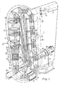
- the hydrothrusting turbine in accordance with Figs. 1, 2, and 2a - 2d, consists of a horizontally placed hollow propulsion axle 1 which is placed by its ends in bearings 36, in which it can freely rotate. On the axle 1 a roller 5 is tightened.
- axle 2 Above and parallel to the axle 1 an axle 2 is situated and is placed in bearings 30 in which it can freely rotate.
- a cogged wheel 32 To the axle 2a a cogged wheel 32 is fixed.
- a cogged endless band 17 is thrown over the wheel 32 and over the roller 5.
- Several floats 9, lined up in series, are fixed to said band.
- the floats 9 are mutually connected by three-armed joint clutches 15.
- a cogged wheel 33 is fixed on the horizontal axle 2.
- a cogged endless band 18 is thrown over the roller 5 and the wheel 33.
- the axle 2 enters into a reducer 31, to the exiting shaft 3 thereof an axle of a generator 7 behind the reducer 31 is connected.
- hollow axle 1 To the hollow axle 1 are connected by lower ends hollow telescopic spokes 14 of changeable length. By their other ends they are connected to an arm of the three-armed joint clutch 15 between floats 9. On the right end of the hollow axle 1 a contact supply clutch 16 is placed on the circumference thereof openings 23 with valves are radially formed.
- the openings 23 with valves are connected to the opening of a supply pipe 8 attached to a compressor6, by which pipe compressed air is driven away from the compressor 6.
- a hose 20 is provided entering into the three-armed clutch 15.
- the hose 20 is filled with compressed air when the corresponding opening 23 with the valve placed on the clutch 16 rotating together with the axle 1 becomes connected to the output opening of the connection pipe 8 of the compressor 6.
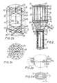
- the floats 9 consist of upper and lower auxiliary floats 10 and a basic float 11.
- Auxiliary floats 10 are formed of cross-placed telescopic sticks 28 situated in two planes on the lower and the front side of the basic float 11. Between the cross-placed telescopic sticks 28 situated in two planes on the lower and the upper front side of the basic float 11 bellows 24 with a metallic cover 25 capable of expanding only horizontally are placed.
- the hose 20 is divided into an upper arm 22 and a lower arm 22.
- the upper arm 21 enters into the lower auxiliary float 10, i.e. into its bellows 24 with the cover 25, while the lower arm 22 enters into the upper auxiliary float 10 of the next float 9, more precisely, into its bellows 24 with the cover 25.
- a partition 27 is placed through which tightly passes the arm 22 of the hose 20.
- the partition 27 has the purpose not to permit entrance of atmospheric air passing through the hollow pipe 1, spoke 14 and clutch 15 into the lower basic float 11, but to enable the entrance of said air only through the upper arm of the clutch 15 into the upper float 9, i.e. into the basic float 11 or the upper float 9.
- a partition 40 is placed under cover 25 with the bellows 24 and above the lower telescopic tsicks 28 in the upper auxiliary float, and above every basic float 11 of the float 9. Its diameter is equal to the diameter of the shrinked float 9 passing through the opening 34 of the tubular gasket 35 which divides the pool V by the funnel 4 from the space A in which exists the pressure of atmospheric air.
- the partition 40 serves for preventing spreading of atmospheric air from the wrappings 38 and the float 9 placed in pool V, into the float 9, which enters into the opening 34 of the tubular gasket 35 during its rotation. When the float 9 enters into the tubular gasket 35, it is shrinked up to the smallest diameter. During this process, the walls of the tubular gasket press wrappings 37 and 38 and also an edge of the partition 40 which prevents in such position an air passage from float 9 placed in pool V, into another float 9, that passes at that moment through the tubular gasket 35.
- the lower auxiliary float 10 of float 9 and the upper auxiliary float 10 of the next lower float 9 become filled by compressed air from the compressor 6 through the corresponding hose 20 (direction a).
- atmospheric air enters (direction b) only into the upper basic float 11 and into cover 39 between the floats 9 through the axle 1 (Figs. 1 and 2), the hollow spoke 14 and through the clutch 15 next to the hose 20 and the upper arm 21 of the hose 20 that enters into the lower auxiliary float 10 of the upper float 9, due to the fact that the hollow clutch 15 is connected by the upper hollow arm 21 with the space of the basic float 11 of the upper float 9.
- the left part of the endless propulsion toroidal band 17 with the floats 9 passes through the pool V with fluid in the part of funnel 4 that is marked by the axis of symmetry 41. It represents the active part of the working wheel K. Thrust of sufficient intensity acts on it from the depth of the pool V towards the surface of the fluid and it pulls the whole series of floats 9 formed as a closed loop.
- the pulling part of the working wheel K consisting of a series of thrusting floats spreads in pool V with fluid, for example water and develops into a conical volume during operation, while it shrinks during an empty stroke into a compact hose of an initial radius of the float 9.
- the cover wrappings 37 and 38 which cover the metal construction of float 9 of a changeable volume, are made of vertical wrinkles 12 along the basic float 11, and of transversal wrinkles 13 on the wrapping 39 between the floats 9.
- the floats 9 are mutually connected by the outer wrapping 39.
- the wrappings 37, 38, and 39 under operating conditions in water form a series of floats 9 with the appearance of truncated cones which create a joint floating volume of maximum thrust of a conical form, i.e. all floats 9 in the water pool V form a conical volume in the upward direction.
- transversal wrinkles 13 on the wrapping 39 between two floats 9 in horizontal direction begins, due to the influence of the difference between the force of water thrust and the tension resistance existing on the entry of the propulsion part of the wheel K into the fluid on one side, and due to the resistant forces and atmospheric air that enters through the axle 1, the spoke 14, and the clutch 15 on the other side.
- the vertical wrinkles 12 of the basic float 11 and the transversal wrinkles 13 of the wrapping 39 thrust the metallic framework intended for the expansion of each float 9 during operation.
- the vertical wrinkles 12 permit the expansion of the basic float 11 in the horizontal plane of the system, while the transversal wrinkles 13 do the same along the horizontal plane along the arc of the elliptic route of the wheel K.
- the metallic construction of all basic floats 11 and the auxiliary floats 10 is placed within the cover wrappings 37 and 38, thus forming complete sets of framework constructions that enable a simultaneous expansion of the auxiliary float 10 and the basic float 11, depending on the height of the fluid column above the transversal section of the corresponding surface.
- the central hollow carrier s6 represents the basic metallic construction of each basic float 11.
- Hollow telescopic sticks 28 are connected with said carrier which expand in the form of a star with a plurality of arms into two upper and two lower horizontal planes on the height h (Figs. 2, 2a - 2c) on both front sides of the basic float 11.
- On their terminal ends are placed vertically connected supporting hollow vertical sticks 29 for thrusting, i.e. for expanding the vertical wrinkles 12 during operation.
- Metallic telescopic sticks 28 form in two horizontal upper and two horizontal lower planes on height h auxiliary floats 10 placed in pairs in a star-like connection on the central carrier 26.
- Transversal telescopic sticks 28 are connected in pairs on the connecting place of the joint 19 and the arms of clutch 15 between the floats 9 (Figs. 1 and 2) fixed to the transportation band 17.
- Plate bellows 24 are placed between two metallic constructions of the transversally placed telescopic sticks 28 in pairs, on the height h in the lower and the upper basis of the auxiliary float 10. In this occasion, the bellows 24 are inserted inside a net-like cover 25 (Fig. 2b and 2d) that has a toroidal form.
- the bellows 24 and the cover 25 are made of elastic material of changeable volume in the horizontal plane only.
- the elastic pneumatic bellows 24 are secured by a net-like toridal cover 25 that should disable creation of 'balloons' between the telescopic sticks 28.
- the cover 25 is made of metal and it ensures the regular pressure arrangement of the whole horizontal plane of the float 9 as shown in Figs. 2, 2a, 2b, and 2d.
- the starry telescopic sticks 28 arranged in pairs limit the auxiliary float 10 from the lower and the upper basis side to a constant height h.
- the construction permits only an expansion of the auxiliary float 10 and the basic float 11 along a horizontal axis where all floats 9 during operation obtain the form of a truncated cone with the top turned upside down as shown on Figs. 1,2, and 2a.
- Arc supporting wrapping firm bands of the same width as the height h forming the wrappings 37 of the auxiliary float 10 are fixed to the end of the changeable telescoping sticks 28 (Figs. 2b and 2c).
- This supporting band, i.e. wrapping 37, thrusts the vertical supporting carriers 29 in order to enable the changeable volume of float 9 on all heights in the working wheel K.
- Compressed air is brought into the auxiliary floats 10, thus used for their expansion, while the cavity of the spoke 14 and the axle 1 enables the atmospheric air to fill up the rarefied milieu in each basic float 11 during operation and in the wrappings 37 and 39.
- the floats 9 of the floating volume are reduced to the initial diameter of the cylindrical hollow hose that is able to pass through the input opening 34 in the tubular gasket 35 placed at the intersection water/air near the bottom of the pool V.
- the wheel K with the floats 9 passes through the opening 34 of the tubular gasket 35 placed at the intersection water/air, i.e. between the pool V and the space A of atmospheric air in funnel 4.
- the tubular gasket 35 has the opening 34 through which pass the floats 9 and a vertical channel 4s through which passes the arm of the clutch 15 to which arm is connected the end of the hollow spoke 14 by the joint 41.
- the width of the channel 42 is equal to the diameter of the arm of the clutch 15. Then, the wheel K with the floats 9 continues movement through the pool V of the elliptic tunnel, the funnel 4′, with a gasket.
- the massive part of the tunnel 4 made of firm material, together with the tubular gasket 35, disables the penetration of fluid into the airy part of the space A.
- the tunnel 4 has the form of a funnel bent as an ellipse like an elliptic tunnel on the narrowest transversal section of which, i.e. the intersection water/air, is performed the minimum volume of each float 9 and represents the passive volume.
- the narrow funnel-type part of tunnel 4 in which atmospheric pressure exists is supposed to enable timely reduction of the basic volume of the float 9 until the initial size is obtained.
- This source compulsively changes the floating volume of the working floats 9 in the fluid of pool V depending on reduction of height of the hydrostatic column.
- the pliers prevent atmospheric air to expand into other floats 9 placed in the air behind that float 9 from which the air is released compulsively, due to the pressure of the pliers.
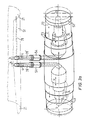
- the hydrothrusting turbine as illustrated in Figs. 3 and 3a, according to a second embodiment of the invention, consits of a horizontally placed hollow axle 51 that is placed in bearings 63 by its narrow extensions 52 and is rotating in said bearings.
- Carrying spokes 54 are firmly connected through their ends with the broadened part 55 of the axle 51. Their other ends are connected with middle parts of the vertical cylindric hollow floats 53 that are lined on a gasket wheel 7 around the broadened part 55 of the axle 51 and form a working wheel K1. Two spokes 54 are connected with each float 53 by their other ends.
- the stationary housing V of the hydrothrusting turbine is adapted to the form of the working wheel K1. It is located on land and partially in water.
- the elliptic and curved funnel is placed mostly in the air and connected at the opening of the water gate 64 where the funnel has the smallest diameter.
- the entry part of the funnel is shown as a semi-chamber like the entrance of a submarine, in order to decrease water pressure.
- the wall of the housing is cut through at the place at which it divides the water pool from the air funnel, in order to enable passage of the gasket wheel from water to air.
- the performance of the driving floats 53 is achieved by double telescopic sticks for the auxiliary floats 74 and the basic floats 53 having changeable volumes during operation.
- Every basic float 53 has its own auxiliary float 74 having the tenth part of its volume.
- the working wheel is formed by several floats arranged in a series and producing a changeable floating volume in the water part of the space using three kinds of energy:
- An axle 67 is placed under the right extension 52 of the axle 61 and parallel thereto. Fixed thereto is the cogged wheel 68 toothed into the cogged wheel 65 on the extension 52 of the axle 51. Behind the wheel 68, the axle 67 enters into a reducer 66, with the exiting shaft 77 thereof the axle of the generator 57 is connected.
- Openings 78 with valves are provided radially on the bulk of the contact clutch 60.
- the openings 78 are connected with openings of the supply pipe 58, the other end thereof is connected with the compressor 56 that supplies compressed air to the floats 53.
- From each opening 78 through hollow parts of the extension 52 of the axle 51 spreads the supply hose 71 dividing into two arms 71 in hollow parts of both spokes 54 entering into the corresponding float 53.
- the supply hose 71 is filled automatically by compressed air (direction a) when the valve opening 78 on the clutch 60 for the corresponding hose 71 arrives to the exiting opening of the connecting pipe 58 from the compressor 56. Compressed air and atmospheric air exit from the float 53 during exhaustion in the direction b through the hollow spokes 54 and the axle 1 into the atmosphere.
- the rectangular openings 61 are provided on the front sides of the broadened part 55 of the axle 1 and they are in continuous connection with atmospheric air that can circulate in both directions (directions c and d) into the float 53 and in the opposite direction.
- the circular openings 62 are provided at front sides of a broadened part 55 of the axle 51. Inserted therein they have contact feeding exhaust valves for attaching connecting contact hoses for fluid supply for the propulsion of the working units, such as hydraulic pliers used for exhausting the floats 53 when they emerge from the water surface into airy space A (this is not shown in the Figures, because this is already known).
- the floats 53 consist of auxiliary floats 74 and the basic float 73 (Fig. 3a).
- the basic float 73 and the auxiliary floats 74 are connected so that changes of volume of the auxiliary floats 74 change the whole volume of the basic float 73.
- Auxiliary floats 74 are placed so that they both change their volume simultaneously.
- the auxiliary floats 74 are performed with telescopic pistons.
- the ends of the spoke 54 through which pass the corresponding arms 71 are connected with a starting cylinder of the auxiliary floats 74.
- Compressed air from the arms 71 flowing through the hollow telescopic auxiliary floats 74 stretches also the basic float 53 because of their mutual firm connection.
- the basic float 53 can be made, for example, in such a way that it can expand in the axial direction, due to the influence of the telescopic pistons.
- the essential feature is that the basic float 53 changes its volume in axial direction depending on the hydrostatic column height.
- the change of volume of the basic float 53 is performed by compulsory movement of a basis 72 caused by initial pressure of compressed air from compressor 56 during starting charge, while the other part of vertical expansion is performed in a self-propelled manner by entrance of atmospheric air through the openings 61 on the whole way along the useful route of the floating volume.
- the working wheel K1 passes with its third part of floats 53 (Fig. 1) always through the pool V with water of corresponding depth.
- partition 70 a tubular gasket is placed in which is provided a rectangular opening 64 through which passes the cylindric floats 53 having the initial volume, because air is exhausted therefrom.
- the tubular gasket 69 disables passage of water into the airy part of space A. Gaps between the cylindric floats 53 are thus filled by the envelope 79 made of a sealing material.
- the hydrothrusting turbine according to the present invention is subjected to changes regarding changes of dimensions, form, and material as well as application for other purposes without surpassing the limits of the present invention.
Landscapes
- Engineering & Computer Science (AREA)
- Chemical & Material Sciences (AREA)
- Combustion & Propulsion (AREA)
- Mechanical Engineering (AREA)
- General Engineering & Computer Science (AREA)
- Other Liquid Machine Or Engine Such As Wave Power Use (AREA)
Applications Claiming Priority (2)
| Application Number | Priority Date | Filing Date | Title |
|---|---|---|---|
| YU1672/86 | 1986-09-29 | ||
| YU167286 | 1986-09-29 |
Publications (1)
| Publication Number | Publication Date |
|---|---|
| EP0262645A1 true EP0262645A1 (de) | 1988-04-06 |
Family
ID=25555129
Family Applications (1)
| Application Number | Title | Priority Date | Filing Date |
|---|---|---|---|
| EP87114222A Withdrawn EP0262645A1 (de) | 1986-09-29 | 1987-09-29 | Turbine mit hydrostatischem Auftrieb |
Country Status (1)
| Country | Link |
|---|---|
| EP (1) | EP0262645A1 (de) |
Cited By (7)
| Publication number | Priority date | Publication date | Assignee | Title |
|---|---|---|---|---|
| EP0452601A1 (de) * | 1990-04-20 | 1991-10-23 | Alexandre Fabry | Auftriebsmotor |
| NL1005213C2 (nl) * | 1997-02-07 | 1998-01-07 | Theodorus Jordanus Roeleveld | Energiebron met regelbare arbeidsafgiften. |
| GB2430471A (en) * | 2005-09-26 | 2007-03-28 | Blaise Coonan | Variable volume buoyancy engine |
| WO2008031179A1 (en) * | 2006-09-11 | 2008-03-20 | Mario Teixeira Cavalheiro | Hydrostatic driven mechanism |
| ES2343048A1 (es) * | 2008-07-10 | 2010-07-21 | Quintiliano Moran Arriero | Motor sin gasto. |
| ES2699435A1 (es) * | 2017-09-05 | 2019-02-11 | Eventos Andalucia 2020 S L | Circuito cerrado y autónomo con corrientes y flujos internos de fluidos y cuerpos por empuje de Arquímedes con refuerzo magnético para generación de energía mecánica y eléctrica y procedimiento de funcionamiento |
| IL303042B1 (en) * | 2023-05-16 | 2025-02-01 | David Crispin | Sleeve vibration by springs |
Citations (4)
| Publication number | Priority date | Publication date | Assignee | Title |
|---|---|---|---|---|
| FR328117A (fr) * | 1902-10-25 | 1903-12-30 | Christofleau Justin Etienne | Système de moteur aéro-hydraulique |
| DE160493C (de) * | 1904-04-22 | 1905-05-10 | Eduard Haubrecht | Auftrieb-kraftmaschine |
| FR1244375A (fr) * | 1959-09-14 | 1960-10-28 | Dispositif rotatif à fonctionnement pneumatique et hydrostatique | |
| FR2215098A5 (de) * | 1973-01-19 | 1974-08-19 | Los Antoni |
-
1987
- 1987-09-29 EP EP87114222A patent/EP0262645A1/de not_active Withdrawn
Patent Citations (4)
| Publication number | Priority date | Publication date | Assignee | Title |
|---|---|---|---|---|
| FR328117A (fr) * | 1902-10-25 | 1903-12-30 | Christofleau Justin Etienne | Système de moteur aéro-hydraulique |
| DE160493C (de) * | 1904-04-22 | 1905-05-10 | Eduard Haubrecht | Auftrieb-kraftmaschine |
| FR1244375A (fr) * | 1959-09-14 | 1960-10-28 | Dispositif rotatif à fonctionnement pneumatique et hydrostatique | |
| FR2215098A5 (de) * | 1973-01-19 | 1974-08-19 | Los Antoni |
Cited By (9)
| Publication number | Priority date | Publication date | Assignee | Title |
|---|---|---|---|---|
| EP0452601A1 (de) * | 1990-04-20 | 1991-10-23 | Alexandre Fabry | Auftriebsmotor |
| NL1005213C2 (nl) * | 1997-02-07 | 1998-01-07 | Theodorus Jordanus Roeleveld | Energiebron met regelbare arbeidsafgiften. |
| GB2430471A (en) * | 2005-09-26 | 2007-03-28 | Blaise Coonan | Variable volume buoyancy engine |
| WO2008031179A1 (en) * | 2006-09-11 | 2008-03-20 | Mario Teixeira Cavalheiro | Hydrostatic driven mechanism |
| ES2343048A1 (es) * | 2008-07-10 | 2010-07-21 | Quintiliano Moran Arriero | Motor sin gasto. |
| ES2343048B1 (es) * | 2008-07-10 | 2011-02-01 | Quintiliano Moran Arriero | Motor sin gasto. |
| ES2699435A1 (es) * | 2017-09-05 | 2019-02-11 | Eventos Andalucia 2020 S L | Circuito cerrado y autónomo con corrientes y flujos internos de fluidos y cuerpos por empuje de Arquímedes con refuerzo magnético para generación de energía mecánica y eléctrica y procedimiento de funcionamiento |
| IL303042B1 (en) * | 2023-05-16 | 2025-02-01 | David Crispin | Sleeve vibration by springs |
| IL303042B2 (en) * | 2023-05-16 | 2025-06-01 | David Crispin | Sleeve vibratioe springs |
Similar Documents
| Publication | Publication Date | Title |
|---|---|---|
| KR102309723B1 (ko) | 질량 변위를 이용하여 유체로부터 에너지를 수거하는 장치 및 방법 | |
| US4135364A (en) | Air lift pump energy conversion apparatus | |
| US3934964A (en) | Gravity-actuated fluid displacement power generator | |
| US4981015A (en) | Buoyancy engines | |
| EP0262645A1 (de) | Turbine mit hydrostatischem Auftrieb | |
| US4095423A (en) | Apparatus for harnessing tidal power | |
| US7434396B2 (en) | Economy of motion machine | |
| BRPI0714369B1 (pt) | método para a conversão de energia cinética e sistema para implementação de referido método | |
| WO2013110926A2 (en) | Power generating apparatus | |
| JP2010525239A (ja) | 利用可能なエネルギーを生成する装置および方法 | |
| CA2548690A1 (en) | Self-propelled energy generator | |
| US5491366A (en) | Leak prevention in underwater power generation | |
| WO2004067953A1 (en) | Hydro-pneumanator | |
| DE19818549A1 (de) | Verfahren und Vorrichtung zur ökologischen Nutzung der Energie offener Fluidströme | |
| WO2017034504A1 (ru) | Бесплотинная гидроэлектростанция | |
| RU2139972C1 (ru) | Подводная гидроэлектростанция | |
| SU1499005A1 (ru) | Маховик переменного момента инерции с вертикальной осью вращени | |
| KR900002959B1 (ko) | 파력발전 방법 및 그 장치 | |
| WO2008150149A1 (fr) | Dispositifs gravitationnels à force hydraulique destinés à la protection de la noosphère d'objets spatiaux | |
| WO2012067533A1 (ru) | Устройство отбора энергии текучей среды | |
| CA3029652C (en) | Energy harvesting from moving fluids using mass displacement | |
| WO2017093826A1 (es) | Sistema hidraulico reciprocante | |
| ES2633840A1 (es) | Sistema de bombeo hidráulico a alta presión sin consumo energético externo y procedimiento para la puesta en práctica del mismo | |
| RU2828144C1 (ru) | Пневмогидравлический двигатель | |
| RU22509U1 (ru) | Пневмогидростатический двигатель |
Legal Events
| Date | Code | Title | Description |
|---|---|---|---|
| PUAI | Public reference made under article 153(3) epc to a published international application that has entered the european phase |
Free format text: ORIGINAL CODE: 0009012 |
|
| AK | Designated contracting states |
Kind code of ref document: A1 Designated state(s): AT BE CH DE ES FR GB GR IT LI LU NL SE |
|
| 17P | Request for examination filed |
Effective date: 19881004 |
|
| STAA | Information on the status of an ep patent application or granted ep patent |
Free format text: STATUS: THE APPLICATION IS DEEMED TO BE WITHDRAWN |
|
| 18D | Application deemed to be withdrawn |
Effective date: 19900403 |