EP0262693B1 - Cabine de photographie et procédé - Google Patents
Cabine de photographie et procédé Download PDFInfo
- Publication number
- EP0262693B1 EP0262693B1 EP87116846A EP87116846A EP0262693B1 EP 0262693 B1 EP0262693 B1 EP 0262693B1 EP 87116846 A EP87116846 A EP 87116846A EP 87116846 A EP87116846 A EP 87116846A EP 0262693 B1 EP0262693 B1 EP 0262693B1
- Authority
- EP
- European Patent Office
- Prior art keywords
- booth
- platform
- camera
- film
- image
- Prior art date
- Legal status (The legal status is an assumption and is not a legal conclusion. Google has not performed a legal analysis and makes no representation as to the accuracy of the status listed.)
- Expired - Lifetime
Links
- 230000005540 biological transmission Effects 0.000 claims abstract 2
- 238000005286 illumination Methods 0.000 claims description 8
- 230000003287 optical effect Effects 0.000 claims description 5
- 230000008878 coupling Effects 0.000 claims description 4
- 238000010168 coupling process Methods 0.000 claims description 4
- 238000005859 coupling reaction Methods 0.000 claims description 4
- 238000006073 displacement reaction Methods 0.000 claims 1
- 240000007320 Pinus strobus Species 0.000 description 5
- 239000011521 glass Substances 0.000 description 2
- 239000000463 material Substances 0.000 description 2
- 239000005304 optical glass Substances 0.000 description 2
- 241001465754 Metazoa Species 0.000 description 1
- 230000006978 adaptation Effects 0.000 description 1
- 238000012937 correction Methods 0.000 description 1
- 230000000994 depressogenic effect Effects 0.000 description 1
- 230000003760 hair shine Effects 0.000 description 1
- 238000012986 modification Methods 0.000 description 1
- 230000004048 modification Effects 0.000 description 1
- 230000011514 reflex Effects 0.000 description 1
- 230000001020 rhythmical effect Effects 0.000 description 1
- 239000012780 transparent material Substances 0.000 description 1
Images


Classifications
-
- G—PHYSICS
- G03—PHOTOGRAPHY; CINEMATOGRAPHY; ANALOGOUS TECHNIQUES USING WAVES OTHER THAN OPTICAL WAVES; ELECTROGRAPHY; HOLOGRAPHY
- G03B—APPARATUS OR ARRANGEMENTS FOR TAKING PHOTOGRAPHS OR FOR PROJECTING OR VIEWING THEM; APPARATUS OR ARRANGEMENTS EMPLOYING ANALOGOUS TECHNIQUES USING WAVES OTHER THAN OPTICAL WAVES; ACCESSORIES THEREFOR
- G03B17/00—Details of cameras or camera bodies; Accessories therefor
- G03B17/48—Details of cameras or camera bodies; Accessories therefor adapted for combination with other photographic or optical apparatus
- G03B17/50—Details of cameras or camera bodies; Accessories therefor adapted for combination with other photographic or optical apparatus with both developing and finishing apparatus
- G03B17/53—Details of cameras or camera bodies; Accessories therefor adapted for combination with other photographic or optical apparatus with both developing and finishing apparatus for automatically delivering a finished picture after a signal causing exposure has been given, e.g. by pushing a button, by inserting a coin
Definitions
- the invention refers to a self photography booth comprising the features a) through f) of claim 1.
- a self photography booth comprising the feratures a) through c) is disclosed in DE-A-30 18 722.
- This booth has an enclosure which is destinated for an individual to be photographed.
- This enclosure has a wall, to which a video camera is adjoined comprising a video camera lens assembly for perceiving an image of a person sitting within said enclosure.
- the video camera is connected with a video recorder, in which the perceived images are stored electronicly.
- a monitor outside the enclosure which is connected with the video recorder as to display the images stored beforehand.
- the individual can watch them after having leaved the enclosure and can decide, which image should be photographed by a film camera disposed within the photography booth.
- the second monitor it is possible to use the first monitor to be photographed by the film camera due to an additional mechanical or electronic device.
- This self photography booth has several disadvantages. For the operation of this booth it is necessary to have a video recorder and a second monitor or mechanical or electronical devices for taking photographes from the monitor. Further, the individual has to leave the enclosure as to observe the images stored in the video recorder. The individual can make some corrections but not in respect to his personal expression and/or pose. During this observation everyone is prohibited to use the photography booth. Finally, and this is a serious disadvantage, the film camera makes photographs only from the monitor which displays images only unsharply so that the photographs are of poor quality. Therefore such photography boothes were not accepted on the market.
- US-A-3 883 883 there is disclosed a remote control device for a film camera.
- the film camera is connected with a video camera which is arranged so that it is opposed to the eye piece of the view finder of the film camera, whereby the optical axes of the view finder and of the image pick up optics are coaxially aligned.
- the video camera is connected to a television monitor with which the image of an object can be observed. Further there are a driving source remotely controlled from the monitor which can operate a distance defining ring of the film camera.
- This device is destinated for the remote control of a film camera so that this camera can be arranged to locations where a person can not stay, e.g. due to dangerous conditions, or because he would disturb the surrounding, e.g. animals to be observed.
- the document do not contain any advise in connection with a photography booth.
- This self photography booth has the advantages that it permits the user to be assured of the image to which the film is exposed, because the image perceived by the film camera is transmitted to the video camera by coupling both devices together so that the image displayed on the video means is in accordance with that perceived by the film camera.
- the user can pose before the film camera and can simultaneously observe his posing until he has reached a desired pose.
- the photographs made by the film camera have high quality because the lens of the film camera is directed to the user to be photographed.
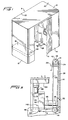
- Booth B as best shown in Figure 1, includes a top 10, a rear end wall 12 and first side wall 14. It can be noted in Figure 1 that side wall 14 has an opening 16 therein which may be selectively blocked by movable curtain 18.
- the curtain 18 is of a heavy weight material which is substantially opaque to light to prevent entrance thereof into the booth B, as will be further explained.
- Booth B furthermore includes a front end wall 20 and a second side wall 22, which has an opening 24 therein which is also selectively blocked by movable curtain 26.
- Figure 1 furthermore discloses a front wall 28 disposed forwardly of front end wall 20 within the interior of booth B.
- Cushion 30 is illustrated in phantom in Figure 1 and is spaced from but in alignment with front wall 28.
- FIG. 2 illustrates front wall 28.
- Front wall 28 has a first opering 32 therein to which cover plate 34 is affixed.
- Second opening 36 is disposed below opening 32 and video monitor 38, which is substantially the same as a conventional television, is positioned in opening 36. It can be noted in Figure 2 that the openings 32 and 36 are closely disposed relative to each other, for reasons to be explained.
- Panes 40 and 42 are mounted to front wall 28 adjacent each other and slightly above opening 32.
- the panes 40 and 42 are, preferably, manufactured of glass or suitable material which is substantially transparent to light.
- cover pane 44 is also mounted to front wall 28 above panes 40 and 42 and substantially spans the distance between side walls 14 and 22. As with panes 40 and 42, cover pane 44 is manufactured from glass or other similar optically transparent material.
- Horizontal support 46 extends between the side walls 14 and 22 and end wall 20 and front wall 28, as best shown in Figure 3. Spaces parallel vertical supports 48 and 50 extend from horizontal support 46 on either side of opening 36 and terminates short of opening 32. Horizontal support 52 extends from vertical support 48 to side wall 14 and support 54 extends from vertical support 50 to side wall 22.
- Strobes 56 and 58 are mounted to the supports 52 and 54, respectively, and are aligned with the panes 40 and 42, respectively.
- the strobes 56 and 58 are of a type conventionally used by photographers and provide a sudden intense burst of illumination.
- the strobes 56 and 58 are sized and selected to provide sufficient illumination for a user of the booth B, when seated on the seat 30, to have a properly illuminated photograph taken thereof.
- Fixture 60 is secured to side wall 14 and a corresponding fixture 60 is secured to side wall 22.
- a color balanced bulb 62 extends between the aligned fixtures 60 and provides illumination corresponding substantially to daylight. The light of the bulb 62 shines through the cover pane 44, preferably at all times. Those skilled in the art will appreciate that more than one bulb 62 is normally used, there being a sufficient number of bulbs to provide adequate illumination for the interior of the booth B.
- Rod 64 extends between the vertical supports 48 and 50 and defines a pivot axis for platform 66 which is disposed rearwardly of the front wall 28 and proximate endwall 20.
- brackets 68 and 78 are secured to rod 64 and horizontal members 72 and 74 extend therefrom, respectively.
- Platform member 66 is secured to the members 72 and 74, preferably by screws 76.
- a brace 78 extends between the members 72 and 74 at the ends thereof opposite the rod 64.
- Vertical supports 80 and 82 extend from the members 72 and 74, respectively, and are maintained in spaced apart parallel relation by member 84 extending therebetween.
- Horizontal members 86 and 88 extend therefrom, on opposite sides thereof, and are likewise maintained in spaced apart parallel relation by member 90.
- Film camera 92 is secured to platform 66 and includes a lens 94 extending forwardly thereform.
- the lens 94 is aligned with the opening 32.
- the camera 92 furthermore includes a conventional shutter assembly 96, as best shown in Figure 6, which is connected with zoom lens 98.
- film camera 92 is of the single lens reflex type wherein the user looks through the lens 94 by means of an eyepiece.
- the conventional optical glass eyepiece is removed and is replaced with a housing 100 at the rear of camera 92.
- Right angle prism 102 is mounted in housing 100 so that the image perceived by the lens 94 is directed vertically upon exiting the camera 92, rather than horizontally parallel to the lens 94, as would normally be the case.
- the prism 102 couples the camera outlet with the video camera lens 106 and assures that the perceived image is diverted to the video camera 104.
- the optical glass of the view piece is removed because I have learned that too much light loss occurs when this eyepiece is in place.
- Video camera 104 is secured to the members 84 and 90 and has a lens assembly 106 with an image opening which is in alignment with the right angle prism 102. In this way, the image received by the lens 94 is transmitted by the prism 102 to the lens 106 of the video camera 104. Because the members 90 and 84 are secured to the members 80 and 82, the alignment of the lens 106 with the prism 102 is always maintained in proper orientation. Therefore, the platform 66 may pivot on the axis defined by the rod 64.
- support 108 is secured to the rear surface 110 of front wall 28.
- Motor drive 112 is mounted to support 108 and has a rotatable shaft 114 to which reel 116 is secured.
- Sheave 118 is rotatably mounted to member 74 by rod 120, as best shown in Figure 5.
- Cord 122 has several wraps thereof wound about reel 116 and extends therefrom about sheave 118.
- the remote end 124 of the cord 122 is secured to the support 108. In this way, rotation of the shaft 114 causes the cord to be wrapped upon or from, depending upon the rotation of the shaft 114, the reel 116 so that the changes in length thereof causes the rod 64 to pivot about its axis, and thereby angularly displace the platform 66, and hence the vertical positioning of the lens 94.
- Figure 4 illustrates the path which the image perceived by the lens 94 takes prior to being displayed on the video monitor 38. Because the camera 92 is of the type wherein the user sights through the lens 94, then the image received by the video camera 104 is the same as that to which the film in the camera 92 would be exposed upon the shutter assembly 96 being operated. The video monitor 38 therefore displays the actual image which is sighted in the lens 94. The user can therefore be assured that the image being displayed on the monitor 38 is the actual image which will be exposed to the film contained in the camera 92.
- Control cable 126 extends from front wall 28 and is connected to control module 128.
- Module 128 includes pivot up button 130, pivot down button 132, zoom in button 134 and zoom out button 136.
- Control module 128 furthermore includes horn button 138 and shutter operator button 140.
- the up and down buttons 130 and 132 are each in electrical connection with motor drive 112 and cause the shaft 114 to rotate in order to take up or let out the cord 122, and thereby cause pivoting of the platform 66.
- the zoom in and zoom out buttons 134 and 136 are connected through control cable 142 to the zoom lens 98.
- the shutter operator button 140 is connected by the control cable 142 to the shutter assembly 96, as best shown in Figure 6. In this way, the operator can pivot the platform up and down in order to vertically adjust the image which is perceived by the lens 94. Likewise, operation of the buttons 136 and 138 causes the lens 98 to be appropriately adjusted.
- LED's 144 extend annularly about the cover plate 34 with respect to the lens 94.
- the LED's 144 pulsate in a rhythmic pattern in order to draw the attention of the person to be photographed to the lens 94. This assures that the person to be photographed is looking into the lens 94, a feature particularly important when the control module 128 is being operated by a person other than the one whose picture is being taken.
- Horn 146 is connected to the horn button 138 and is activated thereby in order to draw the attention of the person seated on the seat 30 toward the front wall 28. Such a feature is particularly desirable with children who might otherwise not be looking forwardly, let alone toward the lens 94.
- the video monitor 38 is disposed closely proximate the lens 94. This is advantageous because it is important that the person who is being photographed not have the eyes looking downwardly, such as could occur if the video monitor 38 was spaced a large distance from the lens 94. Having the lens 94 closely disposed relative to the monitor 38 assures that an individual can be photographed properly and yet be able to look into the lens 94 and at the monitor 38.
- Operation of the booth B for self-photography is relatively simple and straightforward.
- the person to be photographed need merely enter through the opening 16 and be seated on the cushion 30.
- the curtains 18 and 26 are then closed in order to substantially eliminate external illumination which could otherwise detract from the quality of the photograph.
- the bulbs 62 are color balanced to simulate daylight in order to provide a natural appearing photograph, particularly when the strobes 56 and 58 are activated.
- the person to be photographed aligns or poses before the lens 94 and views the image perceived by the lens 94 in the monitor 38. Because of the close positioning of the monitor 38 to the lens 94, then the image displayed corresponds with the image perceived by the lens 94.
- the optical system provided by the right angle prism 92 is such that the image perceived by the lens 94 is transmitted to the video camera 104, and hence to the monitor 38.
- the user can pivot the platform upwardly or downwardly, as well as zoom in or zoom out as may be required until a preferred pose is achieved.
- the user can continuously watch the monitor 38 until the proper pose is achieved.
- the shutter operating button 140 is depressed. Operation of this button 140 causes the strobes 56 and 58 to illuminate the interior of the booth B at essentially the same time that the shutter assembly 96 causes the film in the camera 92 to be exposed. Because of the optical system provided by the camera 92, which is of the looking-through the lens type, then the image exposed on the film corresponds with the image displayed on the monitor.
Landscapes
- Physics & Mathematics (AREA)
- General Physics & Mathematics (AREA)
- Viewfinders (AREA)
- Micro-Organisms Or Cultivation Processes Thereof (AREA)
- Traffic Control Systems (AREA)
- Accessories Of Cameras (AREA)
- Cameras In General (AREA)
- Cameras Adapted For Combination With Other Photographic Or Optical Apparatuses (AREA)
Claims (16)
caractérisée par le fait que
a) une courroie souple (122) présentant un premier brin en prise avec ladite plate-forme (66), et un second brin enroulé roulé autour d'un tambour (116), de telle sorte qu'une rotation dudit arbre (114) provoque un enroulement de ladite courroie (122) à partir dudit tambour (116), afin de faire varier sa longueur pour provoquer, de la sorte, un pivotement de ladite plate-forme (66).
a) lesdits moyens de couplage comprennent un prisme (102) pour diriger, vers ladite caméra vidéo (104), l'image provenant dudit appareil photographique (92).
a) des moyens (62) d'illumination vidéo sont montés sur ladite paroi (28), au-dessus desdits moyens stroboscopiques (56, 58), pour provoquer une illumination de ladite caméra vidéo (104).
a) ladite paroi (28) est percée d'une ouverture (32) étroitement rapprochée desdits moyens (38) de visualisation vidéo, et ladite lentille (98) est logée dans ladite ouverture (32) de telle sorte que l'image soit perçue à travers ladite ouverture (32).
a) un module de commande (128) est en liaison interactive avec l'appareil photographique (92), par l'intermédiaire d'un câble de commande (126), de manière à commander le fonctionnement de l'appareil photographique et le fonctionnement des moyens de pivotement.
a) ledit module de commande (128) est en liaison interactive avec ledit moyen moteur (112).
a) ledit module de commande (128) est en liaison interactive avec une lentille de zoomage (98) de l'appareil photographique (92).
a) ledit appareil photographique (92) est du type réflexe à lentille unique.
Priority Applications (1)
| Application Number | Priority Date | Filing Date | Title |
|---|---|---|---|
| AT87116846T ATE64216T1 (de) | 1986-11-19 | 1987-11-14 | Photographierkabine und verfahren. |
Applications Claiming Priority (2)
| Application Number | Priority Date | Filing Date | Title |
|---|---|---|---|
| US06/932,365 US4804983A (en) | 1986-11-19 | 1986-11-19 | Photography booth and method |
| US932365 | 1986-11-19 |
Publications (3)
| Publication Number | Publication Date |
|---|---|
| EP0262693A2 EP0262693A2 (fr) | 1988-04-06 |
| EP0262693A3 EP0262693A3 (en) | 1988-09-21 |
| EP0262693B1 true EP0262693B1 (fr) | 1991-06-05 |
Family
ID=25462207
Family Applications (1)
| Application Number | Title | Priority Date | Filing Date |
|---|---|---|---|
| EP87116846A Expired - Lifetime EP0262693B1 (fr) | 1986-11-19 | 1987-11-14 | Cabine de photographie et procédé |
Country Status (4)
| Country | Link |
|---|---|
| US (1) | US4804983A (fr) |
| EP (1) | EP0262693B1 (fr) |
| AT (1) | ATE64216T1 (fr) |
| DE (1) | DE3770564D1 (fr) |
Families Citing this family (35)
| Publication number | Priority date | Publication date | Assignee | Title |
|---|---|---|---|---|
| US4908640A (en) * | 1987-12-14 | 1990-03-13 | Mamiya Camera Co., Ltd. | Apparatus for taking photograph with monitoring system |
| GB8904535D0 (en) | 1989-02-28 | 1989-04-12 | Barcrest Ltd | Automatic picture taking machine |
| US5016035A (en) * | 1989-08-28 | 1991-05-14 | Myles Jr Robert E | Enclosed self-portrait photographic studio with camera located behind one-way mirror |
| US5196876A (en) * | 1989-11-20 | 1993-03-23 | Thayer Donald O | Photography booth and method |
| US5072246A (en) * | 1989-11-20 | 1991-12-10 | Thayer Donald O | Self photography booth and method |
| GB9001993D0 (en) * | 1990-01-29 | 1990-03-28 | Toy Of The Year Toy Dreams Lim | Photobooth |
| US5184160A (en) * | 1991-03-20 | 1993-02-02 | Foto Fantasy, Inc. | Camera position adjustment device |
| DE4134263A1 (de) * | 1991-10-16 | 1993-04-22 | Oppach Schaltelektronik | Sofortbild-kabine |
| US5262815A (en) * | 1992-05-27 | 1993-11-16 | Consumer Programs Incorporated | Modular photobooth photography system |
| GB2270573A (en) * | 1992-09-12 | 1994-03-16 | Photo Me Int | Photographic self-portrait installations |
| DE9212286U1 (de) * | 1992-09-14 | 1992-12-03 | Rollei Fototechnic GmbH & Co. KG, 3300 Braunschweig | Sucheraufsatz für eine Spiegelreflexkamera |
| US5621492A (en) * | 1995-01-25 | 1997-04-15 | Polaroid Corporation | Distributed photographic system for taking self portraits |
| US6169938B1 (en) | 1995-12-08 | 2001-01-02 | Marconi Commerce Systems Inc. | Transponder communication of ORVR presence |
| US5940121A (en) * | 1997-02-20 | 1999-08-17 | Eastman Kodak Company | Hybrid camera system with electronic album control |
| US6369908B1 (en) | 1999-03-31 | 2002-04-09 | Paul J. Frey | Photo kiosk for electronically creating, storing and distributing images, audio, and textual messages |
| JP4085677B2 (ja) * | 2002-04-04 | 2008-05-14 | ソニー株式会社 | 撮影装置 |
| EP1558015B1 (fr) * | 2002-08-30 | 2009-10-07 | Sony Corporation | Disposition d'extraction d'image, procédé d'extraction d'image, dispositif de traitement d'image, procédé de traitement d'image et dispositif d'imagerie |
| US7189454B2 (en) * | 2003-05-19 | 2007-03-13 | Engelhard Corporation | Carbon coated high luster materials |
| US7209577B2 (en) * | 2005-07-14 | 2007-04-24 | Logitech Europe S.A. | Facial feature-localized and global real-time video morphing |
| US20070230794A1 (en) * | 2006-04-04 | 2007-10-04 | Logitech Europe S.A. | Real-time automatic facial feature replacement |
| US20070250878A1 (en) * | 2006-04-05 | 2007-10-25 | Ryckman Lawrence G | Interactive system for conducting contest |
| US7796869B2 (en) * | 2007-03-23 | 2010-09-14 | Troy Bakewell | Photobooth |
| USD612884S1 (en) * | 2008-01-28 | 2010-03-30 | TheTraveling Photo Booth Inc. | Photo booth |
| US9158179B2 (en) * | 2008-07-14 | 2015-10-13 | The Traveling Photo Booth Inc. | Photo booth systems and methods |
| USD692474S1 (en) * | 2011-08-23 | 2013-10-29 | Jonathan Thorpe | Photo booth |
| US9922356B1 (en) | 2013-01-22 | 2018-03-20 | Carvana, LLC | Methods and systems for online transactions |
| FR3023387A1 (fr) * | 2014-07-03 | 2016-01-08 | Mathieu Pignier | Borne interactive et systeme associe |
| WO2018106887A1 (fr) | 2016-12-07 | 2018-06-14 | Scheich Davo | Chambre photographique de véhicule |
| US11412135B2 (en) | 2018-12-05 | 2022-08-09 | Ovad Custom Stages, Llc | Bowl-shaped photographic stage |
| US11720005B2 (en) | 2019-02-19 | 2023-08-08 | Carvana, LLC | Camera mount for vehicle photographic chambers |
| US11841601B2 (en) | 2019-04-11 | 2023-12-12 | Carvana, LLC | Ovoid vehicle photographic booth |
| WO2020215060A1 (fr) | 2019-04-19 | 2020-10-22 | Ovad Custom Stages, Llc | Palette photographique et procédé d'utilisation de celle-ci |
| US11892757B2 (en) | 2019-04-29 | 2024-02-06 | Carvana, LLC | Vehicle photographic and inspection booth |
| US12061411B2 (en) | 2019-06-06 | 2024-08-13 | Carvana, LLC | Vehicle photographic system for identification of surface imperfections |
| US12126774B2 (en) | 2021-03-19 | 2024-10-22 | Carvana, LLC | Mobile photobooth |
Citations (2)
| Publication number | Priority date | Publication date | Assignee | Title |
|---|---|---|---|---|
| US3883883A (en) * | 1972-09-22 | 1975-05-13 | Canon Kk | Remote control device for camera |
| US4705374A (en) * | 1986-09-11 | 1987-11-10 | Clairmont Camera, Inc. | Tilting viewfinder and video door accessory for motion-picture camera |
Family Cites Families (18)
| Publication number | Priority date | Publication date | Assignee | Title |
|---|---|---|---|---|
| US1794142A (en) * | 1927-08-26 | 1931-02-24 | William C Boston | Posing apparatus for photographic studios |
| US1795051A (en) * | 1928-07-26 | 1931-03-03 | Luther G Simjian | Pose-reflecting system for photographic apparatus |
| US1830770A (en) * | 1929-05-16 | 1931-11-10 | Luther G Simjian | Pose-reflecting system for photographic apparatus |
| US3114002A (en) * | 1960-01-08 | 1963-12-10 | Fernseh Gmbh | Combined television and cinematographic camera |
| US3225140A (en) * | 1963-12-11 | 1965-12-21 | Tele Cam Inc | Combination motion picture and television camera |
| DE1993351U (de) * | 1966-05-31 | 1968-09-05 | Sidam Srl | Durch muenzen zu betaetigendes selbsttaetiges fotografier- und entwicklungsgeraet. |
| DE1277012B (de) * | 1966-12-20 | 1968-09-05 | Asahi Optical Co Ltd | Photozusatz an Fernsehkameras |
| CH477703A (de) * | 1969-01-22 | 1969-08-31 | Autokopie Ag | Verfahren und Einrichtung zur photographischen Herstellung von Positivbildern, insbesondere Portraitaufnahmen |
| US3913116A (en) * | 1972-01-07 | 1975-10-14 | Arnold & Richter Kg | Camera with adjustable viewfinder |
| US3812506A (en) * | 1973-03-16 | 1974-05-21 | I Klebanow | System for child photography |
| DD106089A1 (fr) * | 1973-07-09 | 1974-05-20 | ||
| US3921189A (en) * | 1974-10-11 | 1975-11-18 | Albert F Gallistel | Zoom lens view finder systems |
| JPS52133632U (fr) * | 1976-04-07 | 1977-10-11 | ||
| US4297724A (en) * | 1979-01-24 | 1981-10-27 | Dainippon Screen Seizo Kabushiki Kaisha | Method and machine for trying on a hair form in image |
| JPS5683729U (fr) * | 1979-11-29 | 1981-07-06 | ||
| DE3018722A1 (de) * | 1980-05-16 | 1981-11-26 | Peter Dipl.-Ing. 7730 Villingen-Schwenningen Hettich | Fotographisches system insbesondere schnellphotoautomat zur aufnahme, speicherung mehrerer bilder und auswahl ablichtung und entwicklung eines bildes |
| US4560261A (en) * | 1982-05-07 | 1985-12-24 | Minolta Camera Kabushiki Kaisha | Flat camera with self photograph framing mirror |
| JPH0740723B2 (ja) * | 1986-02-06 | 1995-05-01 | ソニー株式会社 | 画像撮影装置 |
-
1986
- 1986-11-19 US US06/932,365 patent/US4804983A/en not_active Expired - Fee Related
-
1987
- 1987-11-14 AT AT87116846T patent/ATE64216T1/de not_active IP Right Cessation
- 1987-11-14 EP EP87116846A patent/EP0262693B1/fr not_active Expired - Lifetime
- 1987-11-14 DE DE8787116846T patent/DE3770564D1/de not_active Expired - Fee Related
Patent Citations (2)
| Publication number | Priority date | Publication date | Assignee | Title |
|---|---|---|---|---|
| US3883883A (en) * | 1972-09-22 | 1975-05-13 | Canon Kk | Remote control device for camera |
| US4705374A (en) * | 1986-09-11 | 1987-11-10 | Clairmont Camera, Inc. | Tilting viewfinder and video door accessory for motion-picture camera |
Also Published As
| Publication number | Publication date |
|---|---|
| EP0262693A3 (en) | 1988-09-21 |
| EP0262693A2 (fr) | 1988-04-06 |
| US4804983A (en) | 1989-02-14 |
| ATE64216T1 (de) | 1991-06-15 |
| DE3770564D1 (de) | 1991-07-11 |
Similar Documents
| Publication | Publication Date | Title |
|---|---|---|
| EP0262693B1 (fr) | Cabine de photographie et procédé | |
| US4959670A (en) | Photography booth and method | |
| US5844530A (en) | Head mounted display, and head mounted video display system | |
| EP1248144B1 (fr) | Procede de photographie d'objet brillant, procede de photographie de lunettes et procede de preparation de catalogue electronique pour lunettes | |
| US5196876A (en) | Photography booth and method | |
| KR890702391A (ko) | 안경과 같이 머리에 착용 가능한 입체 비디오 영상 디스플레이 장치 | |
| US4704022A (en) | Video finder for single-lens reflex camera | |
| JPH0933986A (ja) | 構図合わせ機能を有するカメラ及び該カメラにおける構図基準点の表示方法 | |
| US5694628A (en) | View finder for camera | |
| US4888605A (en) | Photographing apparatus with self-monitoring device | |
| GB1312569A (en) | Apparatus for taking hemispherical motion pictures | |
| US4896175A (en) | Photography booth and method | |
| CA2211394C (fr) | Systeme photographique reparti pour faire des autoportraits | |
| US3820882A (en) | Automatic diaphragm control for motion picture cameras used on operation microscopes | |
| CA1195421A (fr) | Camera de cinema electronique | |
| US4510529A (en) | Electronic cinema camera | |
| JP3299804B2 (ja) | 眼幅調整可能な映像表示装置 | |
| JP2531184B2 (ja) | カメラのビュ−ファインダ− | |
| JP3298071B2 (ja) | ビデオカメラ | |
| US4943853A (en) | TV viewer | |
| US4652103A (en) | Colposcope with photographic equipment | |
| US4420231A (en) | Motion picture camera | |
| JPH07240889A (ja) | 撮像装置付き頭部装着型映像表示装置 | |
| US5659819A (en) | Apparatus for taking pictures against white backgrounds | |
| US4206997A (en) | Method and device for making combined images for photography |
Legal Events
| Date | Code | Title | Description |
|---|---|---|---|
| PUAI | Public reference made under article 153(3) epc to a published international application that has entered the european phase |
Free format text: ORIGINAL CODE: 0009012 |
|
| AK | Designated contracting states |
Kind code of ref document: A2 Designated state(s): AT BE CH DE ES FR GB GR IT LI LU NL SE |
|
| PUAL | Search report despatched |
Free format text: ORIGINAL CODE: 0009013 |
|
| AK | Designated contracting states |
Kind code of ref document: A3 Designated state(s): AT BE CH DE ES FR GB GR IT LI LU NL SE |
|
| 17P | Request for examination filed |
Effective date: 19890307 |
|
| 17Q | First examination report despatched |
Effective date: 19900129 |
|
| GRAA | (expected) grant |
Free format text: ORIGINAL CODE: 0009210 |
|
| AK | Designated contracting states |
Kind code of ref document: B1 Designated state(s): AT BE CH DE ES FR GB GR IT LI LU NL SE |
|
| PG25 | Lapsed in a contracting state [announced via postgrant information from national office to epo] |
Ref country code: NL Effective date: 19910605 Ref country code: LI Effective date: 19910605 Ref country code: SE Effective date: 19910605 Ref country code: CH Effective date: 19910605 Ref country code: GR Free format text: LAPSE BECAUSE OF FAILURE TO SUBMIT A TRANSLATION OF THE DESCRIPTION OR TO PAY THE FEE WITHIN THE PRESCRIBED TIME-LIMIT Effective date: 19910605 Ref country code: AT Effective date: 19910605 Ref country code: BE Effective date: 19910605 Ref country code: IT Free format text: LAPSE BECAUSE OF FAILURE TO SUBMIT A TRANSLATION OF THE DESCRIPTION OR TO PAY THE FEE WITHIN THE PRE;WARNING: LAPSES OF ITALIAN PATENTS WITH EFFECTIVE DATE BEFORE 2007 MAY HAVE OCCURRED AT ANY TIME BEFORE 2007. THE CORRECT EFFECTIVE DATE MAY BE DIFFERENT FROM THE ONE RECORDED.SCRIBED TIME-LIMIT Effective date: 19910605 |
|
| REF | Corresponds to: |
Ref document number: 64216 Country of ref document: AT Date of ref document: 19910615 Kind code of ref document: T |
|
| REF | Corresponds to: |
Ref document number: 3770564 Country of ref document: DE Date of ref document: 19910711 |
|
| REG | Reference to a national code |
Ref country code: CH Ref legal event code: PL |
|
| PG25 | Lapsed in a contracting state [announced via postgrant information from national office to epo] |
Ref country code: ES Free format text: LAPSE BECAUSE OF FAILURE TO SUBMIT A TRANSLATION OF THE DESCRIPTION OR TO PAY THE FEE WITHIN THE PRESCRIBED TIME-LIMIT Effective date: 19910916 |
|
| ET | Fr: translation filed | ||
| NLV1 | Nl: lapsed or annulled due to failure to fulfill the requirements of art. 29p and 29m of the patents act | ||
| PG25 | Lapsed in a contracting state [announced via postgrant information from national office to epo] |
Ref country code: LU Free format text: LAPSE BECAUSE OF NON-PAYMENT OF DUE FEES Effective date: 19911130 |
|
| PLBE | No opposition filed within time limit |
Free format text: ORIGINAL CODE: 0009261 |
|
| STAA | Information on the status of an ep patent application or granted ep patent |
Free format text: STATUS: NO OPPOSITION FILED WITHIN TIME LIMIT |
|
| 26N | No opposition filed | ||
| PGFP | Annual fee paid to national office [announced via postgrant information from national office to epo] |
Ref country code: GB Payment date: 19921124 Year of fee payment: 6 |
|
| PGFP | Annual fee paid to national office [announced via postgrant information from national office to epo] |
Ref country code: DE Payment date: 19921204 Year of fee payment: 6 |
|
| PGFP | Annual fee paid to national office [announced via postgrant information from national office to epo] |
Ref country code: FR Payment date: 19921216 Year of fee payment: 6 |
|
| PG25 | Lapsed in a contracting state [announced via postgrant information from national office to epo] |
Ref country code: GB Effective date: 19931114 |
|
| GBPC | Gb: european patent ceased through non-payment of renewal fee |
Effective date: 19931114 |
|
| PG25 | Lapsed in a contracting state [announced via postgrant information from national office to epo] |
Ref country code: FR Effective date: 19940729 |
|
| PG25 | Lapsed in a contracting state [announced via postgrant information from national office to epo] |
Ref country code: DE Effective date: 19940802 |
|
| REG | Reference to a national code |
Ref country code: FR Ref legal event code: ST |