EP0262822B1 - Connexion libérable pour train de tubes - Google Patents
Connexion libérable pour train de tubes Download PDFInfo
- Publication number
- EP0262822B1 EP0262822B1 EP87308013A EP87308013A EP0262822B1 EP 0262822 B1 EP0262822 B1 EP 0262822B1 EP 87308013 A EP87308013 A EP 87308013A EP 87308013 A EP87308013 A EP 87308013A EP 0262822 B1 EP0262822 B1 EP 0262822B1
- Authority
- EP
- European Patent Office
- Prior art keywords
- tubing
- release
- string
- mandrel
- housing
- Prior art date
- Legal status (The legal status is an assumption and is not a legal conclusion. Google has not performed a legal analysis and makes no representation as to the accuracy of the status listed.)
- Expired - Lifetime
Links
- 239000012530 fluid Substances 0.000 claims description 42
- 230000009977 dual effect Effects 0.000 claims description 11
- 230000000717 retained effect Effects 0.000 claims description 9
- 230000002706 hydrostatic effect Effects 0.000 claims description 6
- 230000008878 coupling Effects 0.000 description 2
- 238000010168 coupling process Methods 0.000 description 2
- 238000005859 coupling reaction Methods 0.000 description 2
- 238000012986 modification Methods 0.000 description 1
- 230000004048 modification Effects 0.000 description 1
- 238000010008 shearing Methods 0.000 description 1
- 238000013022 venting Methods 0.000 description 1
Images

Classifications
-
- E—FIXED CONSTRUCTIONS
- E21—EARTH OR ROCK DRILLING; MINING
- E21B—EARTH OR ROCK DRILLING; OBTAINING OIL, GAS, WATER, SOLUBLE OR MELTABLE MATERIALS OR A SLURRY OF MINERALS FROM WELLS
- E21B43/00—Methods or apparatus for obtaining oil, gas, water, soluble or meltable materials or a slurry of minerals from wells
- E21B43/11—Perforators; Permeators
- E21B43/116—Gun or shaped-charge perforators
-
- E—FIXED CONSTRUCTIONS
- E21—EARTH OR ROCK DRILLING; MINING
- E21B—EARTH OR ROCK DRILLING; OBTAINING OIL, GAS, WATER, SOLUBLE OR MELTABLE MATERIALS OR A SLURRY OF MINERALS FROM WELLS
- E21B17/00—Drilling rods or pipes; Flexible drill strings; Kellies; Drill collars; Sucker rods; Cables; Casings; Tubings
- E21B17/02—Couplings; joints
- E21B17/04—Couplings; joints between rod or the like and bit or between rod and rod or the like
- E21B17/06—Releasing-joints, e.g. safety joints
-
- E—FIXED CONSTRUCTIONS
- E21—EARTH OR ROCK DRILLING; MINING
- E21B—EARTH OR ROCK DRILLING; OBTAINING OIL, GAS, WATER, SOLUBLE OR MELTABLE MATERIALS OR A SLURRY OF MINERALS FROM WELLS
- E21B23/00—Apparatus for displacing, setting, locking, releasing or removing tools, packers or the like in boreholes or wells
- E21B23/04—Apparatus for displacing, setting, locking, releasing or removing tools, packers or the like in boreholes or wells operated by fluid means, e.g. actuated by explosion
- E21B23/0412—Apparatus for displacing, setting, locking, releasing or removing tools, packers or the like in boreholes or wells operated by fluid means, e.g. actuated by explosion characterised by pressure chambers, e.g. vacuum chambers
-
- E—FIXED CONSTRUCTIONS
- E21—EARTH OR ROCK DRILLING; MINING
- E21B—EARTH OR ROCK DRILLING; OBTAINING OIL, GAS, WATER, SOLUBLE OR MELTABLE MATERIALS OR A SLURRY OF MINERALS FROM WELLS
- E21B23/00—Apparatus for displacing, setting, locking, releasing or removing tools, packers or the like in boreholes or wells
- E21B23/04—Apparatus for displacing, setting, locking, releasing or removing tools, packers or the like in boreholes or wells operated by fluid means, e.g. actuated by explosion
- E21B23/042—Apparatus for displacing, setting, locking, releasing or removing tools, packers or the like in boreholes or wells operated by fluid means, e.g. actuated by explosion using a single piston or multiple mechanically interconnected pistons
-
- E—FIXED CONSTRUCTIONS
- E21—EARTH OR ROCK DRILLING; MINING
- E21B—EARTH OR ROCK DRILLING; OBTAINING OIL, GAS, WATER, SOLUBLE OR MELTABLE MATERIALS OR A SLURRY OF MINERALS FROM WELLS
- E21B43/00—Methods or apparatus for obtaining oil, gas, water, soluble or meltable materials or a slurry of minerals from wells
- E21B43/11—Perforators; Permeators
- E21B43/119—Details, e.g. for locating perforating place or direction
- E21B43/1193—Dropping perforation guns after gun actuation
Definitions
- the present invention relates to a releasable connection for conduit string, and especially but not exclusively to dual tubing release apparatus and actuating apparatus therefor for use in well operations.
- the well completion apparatus described includes an apparatus for the simultaneous decoupling of concentric tubing string through the use of a shifting tool run on a wireline or slickline in the well.
- One of the decoupling apparati includes a movable sleeve positioned between the first and second tubing strings adjacent the couplings for releasing the lower sections thereof. As the movable sleeve is slid by the shifting tool run on a wireline or slickline within a chamber formed between the tubing strings, collet fingers on the detachable couplings are released allowing the lower tubing sections to fall to the bottom of the well with the perforating gun.
- the movable sleeve includes a plurality of lugs which extend through the second tubing string towards the center of the tubing. These lugs can be engaged by a positioning tool lowered on a wireline or slickline into the well. The wireline or slickline can then be raised or lowered causing the sleeve to shift and detach the tubing.
- United States Patent Number 4526233 discloses an apparatus for releasably connecting one portion of a conduit string to another portion thereof, said conduit string being installed in a well bore, and the string and well bore both having fluid therein, said apparatus comprising a tubing release assembly means connecting said one portion of said conduit string to said another portion thereof and capable of being actuated to release said one portion from said another portion thereof upon the communication of a fluid pressure to the tubing release assembly means, the tubing release assembly means including a first member for connection to said one portion of said conduit string; a second member connected to said another portion of said conduit string, said second member having a portion thereof releasably secured to a portion of said first member; and a release member which is movable upon the communication of the fluid pressure to the tubing release assembly means to allow the release of the first member from the second member by the movement of said release member from a first position to a second position whereby said second member releases from engagement from said first member; and independent actuating tool means for use with the tubing release assembly means.
- the present invention is characterised in that the actuating tool means when actuated and in communication with the release assembly means causes a fluid pressure to be communicated to the tubing release assembly means which pressure is less than either the hydrostatic fluid pressure of said fluid in said conduit string or said well bore at the location in said conduit string of said tubing release assembly means, the actuating tool means being adapted to be conveyed through said one portion of said conduit string, the actuating tool means including a member having a chamber therein capable of retaining a desired level of fluid pressure therein; said release member is movable from the first position with respect to said first member and said second member having a portion thereof engaging said first member and said second member to cause said first member and said second member to be releasably secured to each other to the second position with respect to said first member and said second member having a portion thereof remaining in engagement with said portion of said first member and disengaging from said portion of said second member; and said actuating tool means further including means to communicate the desired level of fluid pressure in the chamber of the member of the
- the tubing release assembly means includes: an upper housing comprising a portion of said first member connected to said portion of said conduit string, said upper housing having a portion thereof for connection to said conduit string; an adjustment nut comprising a portion of said second member connected to said another portion of said conduit string, said adjustment nut having a portion thereof connected to said another portion of said conduit string; a lower housing comprising another portion of said second member connected to said another portion of said conduit string, said lower housing having said adjustment nut adjustably secured thereon and having a portion thereof releasably engaging a portion of said upper housing; and said release means comprises a release sleeve slidable within a portion of the upper housing releasably retaining a portion of the upper housing connected to a portion of the lower housing when the release sleeve is in a first position within the upper housing.
- the invention further provides for the tubing release assembly to be installed in a dual conduit string, wherein the upper housing has a portion thereof connected to a portion of one conduit string of said dual conduit strings; the adjustment nut has a portion thereof connected to another portion of one conduit string of said dual conduit strings; said first member comprising a pull tube mandrel having a portion thereof connected to a portion of the other string of said dual conduit strings; said second member comprising a pull tube latch having a portion thereof connected to the pull tube mandrel and another portion thereof connected to another portion of the other string of said dual strings; and wherein said release member comprises a release sleeve slidable within said upper housing, when in a first position in the upper housing, having a portion thereof abutting a portion of the lower housing to prevent the lower housing from disconnecting from the upper housing, and having a portion thereof abutting the pull tube latch to prevent the pull tube latch from disconnecting from the pull tube mandrel, and when in a second position in the upper housing, disengaging from
- the member of the actuating tool means includes a housing; and the actuating tool means further comprises a lower end plug having a portion thereof connected to a portion of the housing; a match drill assembly having a portion thereof connected to the housing; a setting mandrel having a portion thereof slidably, sealingly engaging a portion of the housing and releasably connected to the match drill assembly; an upper element cone slidably, releasably retained on a portion of the setting mandrel; a retrieving mandrel slidably, releasably connected to a portion of the setting mandrel; and an upper end plug having a portion thereof connected to a portion of the setting mandrel and having a portion thereof slidably engaging a portion of the retrieving mandrel.
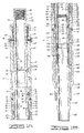
- FIG. 1A a portion of the pull tube mandrel 12, upper housing 14, release sleeve 16, and lower housing 90 are shown.
- the portion of the pull tube mandrel 12 comprises an elongated annular cylindrical member having, on the exterior thereof, first cylindrical surface 20, second cylindrical surface 22 having, in turn, first annular recess 24 therein and second annular recess 26 therein and, on the interior thereof, first threaded bore 28, first cylindrical bore 30, and second cylindrical bore 32 having, in turn, annular recess 34 therein, and third cylindrical bore 36.
- the portion of the pull tube mandrel 12 further includes a plurality of apertues 38 which allow fluid communication between the exterior of the mandrel 12 to the interior thereof.
- the portion of the upper housing 14 comprises an elongated annular cylindrical member having, on the exterior thereof, cylindrical surface 42 and, on the interior thereof, threaded bore 44, first cylindrical bore 46 having, in turn, annular recess 48 therein containing annular elastomeric seal 50 which sealingly engages second cylindrical surface 22 of pull tube mandrel 12, second cylindrical bore 52, third cylindrical bore 54, fourth cylindrical bore 56, fifth cylindrical bore 58, sixth cylindrical bore 60 having a diameter smaller than bore 58 and seventh cylindrical bore 62 having a diameter greater than bore 60.
- the portion of the upper housing 14 shown further includes a plurality of first threaded apertures 64 threadedly receiving a plurality of threaded fasteners 66 therein, a plurality of second threaded apertures 68 receiving a plurality of threaded set screws 70 therein and a plurality of apertures 72 which allow fluid communication from the exterior of the upper housing 14 to the interior thereof.
- the portion of the release sleeve 16 comprises an elongated annular cylindrical member having on the exterior thereof first cylindrical surface 74 having, in turn, annular recesses 76 containing annular elastomeric seals 78 therein and annular recess 80 and second cylindrical surface 82 and, on the interior thereof, cylindrical bore 84 having, in turn, first annular recesses 86 therein containing annular elastomeric seals 88 therein.
- the portion of the lower housing 90 comprises a plurality of collet fingers 92 having enlarged heads 94 thereon having, in turn, exterior surfaces 96 which engage fifth cylindrical bore 58 of upper housing 14 and interior surfaces 98 which slidingly engage second cylindrical surface 82 of release sleeve 16.
- FIG. 1B the remaining portion of the tubing release assembly 10 is shown.
- the remaining portion of the tubing release assembly 10 comprises a portion of pull tube mandrel 12, a portion of upper housing 14, a portion of release sleeve 16, a portion of lower housing 90, adjustment nut 100, pull tube adapter 102, pull tube latch 104, and retainer ring 106.
- the portion of pull tube mandrel 12 comprises an elongated annular cylindrical member having, on the exterior thereof, a continuation of second cylindrical surface 22, and, on the interior thereof, a continuation of third cylindrical bore 36 and second threaded bore 40.
- the portion of the upper housing 14 comprises an elongated annular cylindrical member having, on the exterior thereof, a continuation of cylindrical surface 42 and, on the interior thereof, a continuation of seventh cylindrical bore 62.
- the upper housing 14 further includes annular end surface 108.
- the portion of the release sleeve 16 comprises an elongated annular member having, on the exterior thereof, a continuation of second cylindrical surface 82 and, on the interior thereof, a continuation of cylindrical bore 84 having a second annular recess 110 therein.
- the portion of the lower housing 90 comprises an elongated annular cylindrical member having, connected to one end thereof, a plurality of collet fingers 92, on the exterior thereof, first cylindrical surface 114 which slidingly engages seventh cylindrical bore 62 of upper housing 14, second cylindrical surface 116, and third cylindrical surface 118, and, on the interior thereof, first cylindrical bore which slidingly mates with second cylindrical surface 82 of release sleeve 16 and second cylindrical bore 124.
- the adjustment nut 100 comprises an elongated annular cylindrical member having, on the exterior thereof, first cylindrical surface 126, second cylindrical surface 128 and threaded surface 130 and, on the interior thereof, threaded bore 132 which releasably, threadedly engages threaded surface 120 of lower housing 90 and cylindrical bore 134.
- the adjustment nut 100 further includes a plurality of threaded apertures 131 which releasably, threadedly engages a plurality of set screws 133 installed therein which in turn, have one end thereof engaging third cylindrical surface 118 of lower housing 90.
- the pull tube adapter 102 comprises an elongated annular cylindrical member having, on the exterior thereof, threaded surface 136 which releasably, threadedly engages second threaded bore 40 of pull tube mandrel 12, first cylindrical surface 138, annular shoulder 140, second cylindrical surface 142, and third cylindrical surface 144 having, in turn, annular recess 146 therein and, on the interior thereof, cylindrical bore 148.
- the pull tube latch 104 comprises an elongated annular cylindrical member having, on one end thereof, a plurality of collet fingers 150 having, in turn, enlarged heads 152 thereon which releasably engage annular recess 146 in third cylindrical surface 144 of pull tube adapter 102 and enlarged interior projections 154 which abut the end 156 of pull tube adapter 102, the collet fingers 150 being separated from each other by a plurality of longitudinal slots 158 and, on the exterior thereof, cylindrical surface 160 and threaded surface 162, and, on the interior thereof, cylindrical bore 164.
- a resilient annular retainer ring 106 is installed resiliently engaging second annular recess 110 of cylindrical bore 84 of release sleeve 16 and abutting annular surface 140 of pull tube adapter 102 being retained thereon by the end 166 of pull tube mandrel 12.
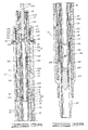
- FIGS. 2A and 2B the upper portion of the air chamber assembly 500 is shown in its preferred embodiment.
- the upper portion of the air chamber assembly 500 includes retrieving mandrel 502, upper end plug 504, a portion of the setting mandrel 506, upper element cone 508, upper shear pin retainer 510, a portion of bonded seal element assembly 512, and release ring 514.
- the retrieving mandrel 502 comprises an elongated cylindrical member having, on one end thereof, threaded surface 516 and on the exterior thereof, first cylindrical surface 518, second cylindrical surface 520 having, in turn, annular recess 522 therein, third cylindrical surface 524 having, in turn, annular recess 526 therein containing annular elastomeric seals 528.
- plug 504 comprises an elongated annular cylindrical member having, on the exterior thereof, frusto-conical surface 530, cylindrical surface 532, and threaded surface 534 and, on the interior thereof, first cylindrical bore 536 which slidingly engages first cylindrical surface 518 of retrieving mandrel 502 and second cylindrical bore 538.
- the portion of the setting mandrel 506 shown comprises an elongated annular cylindrical member having, on the exterior thereof, first cylindrical surface 540 and second cylindrical surface 542 having, in turn, an annular recess 544 therein and, on the interior thereof, threaded bore 546 which releasably, threadedly engages threaded surface 534 of upper end plug 504, first cylindrical bore 548, frusto-conical bore 550, second cylindrical bore 552 having, in turn, annular recess 554 therein, third cylindrical bore 556 which slidingly, sealingly engages annular elastomeric seals 528 on retrieving mandrel 502 and fourth cylindrical bore 558.
- a first plurality of apertures 560 which allow fluid communication between the first cylindrical surface 540 of the exterior of the mandrel 506 and third cylindrical bore 556 of the interior of mandrel 506 and a second plurality of apertures 562 which allow fluid communication between the second cylindrical surface 542 of the mandrel 506 and the fourth cylindrical bore 558 of the mandrel 506.
- the upper element cone 508 comprises an annular cylindrical member having, on the exterior thereof, cylindrical surface 564 having, in turn, annular recess 566 therein and, on the interior thereof, 568 having, in turn, annular recess 570 therein containing annular elastomeric seals 572 which slidingly, sealingly engage second cylindrical surface 542 of setting mandrel 506.
- the upper element cone 508 further includes a plurality of apertures 574 having a plurality of shear pins 576 contained therein which, in turn, have a portion of each pin 576 retained within annular recess 544 of setting mandrel 506.
- the upper shear pin retainer 510 comprises an annular cylindrical member having exterior surface 578, interior surface 580 and a pluality of apertures 582 therein having, in turn, a plurality of threaded pins 584 therein, each pin 584 having a portion thereof engaging annular recess 566 of upper element cone 508.
- the portion of the bonded seal element assembly 512 comprises an elongated, annular cylindrical member having, on one end thereof, annular elastomeric member 586, on the exterior thereof, cylindrical surface 588, on the interior thereof, cylindrical bore 590 and a plurality of apertures 592 therethrough.
- the release ring 514 comprises an annular resilient member which is retained on retrieving mandrel 502 in annular recess 522 therein and resiliently engages annular recess 554 in setting mandrel 506.
- the remaining portion of the air chamber assembly 500 comprises a portion of bonded seal element assembly 512, a portion of setting mandrel 506, lower shear pin retainer 594, match drill assembly 596, housing 598, lower end plug 600 and housing retainer 602.
- the portion of the bonded seal element assembly 512 comprises an elongated, annular cylindrical member having cylindrical surface 588, cylindrical bore 590 and annular elastomeric member 604 bonded to the other end thereof.
- the portion of setting mandrel 506 comprises an elongated annular cylindrical member having, on the exterior thereof, a continuation of second cylindrical surface 542 having, in turn, second annular recess 606 therein, third annular recess 608 therein and fourth annular recess 610 therein containing annular elastomeric seal 613 and, on the interior thereof, a continuation of fourth cylindrical bore 558.
- the lower shear pin retainer 594 comprises an annular cylindrical member having exterior cylindrical surface 614 and interior cylindrical bore 616.
- the match drill assembly 596 comprises an elongated annular cylindrical member having, on the exterior thereof, first cylindrical surface 618 and second cylindrical surface 620 and, on the interior thereof, first cylindrical bore 622 having, in turn, annular recess 624 therein containing annular elastomeric seal 626 which slidingly, sealingly engages second cylindrical surface 542 of setting mandrel 506, second cylindrical bore 628, and threaded bore 630.
- the match drill assembly further includes a first plurality of apertures 632 having, in turn, a plurality of shear pins 634 therein, each pin 634 having a portion thereof engaging third annular recess 606 in setting mandrel 506 and a second plurality of aperatures 636 which allow fluid communication from the exterior of the match drill assembly 596 to the interior thereof.
- the housing 598 comprises an elongated annular cylindrical member having, on the exterior thereof, threaded surface 638 which threadedly engages threaded bore 630 of match drill assembly 596, first cylindrical surface 640, first annular frusto-conical surface 642, second cylindrical surface 644, second annular frusto-conical surface 646, and third cylindrical bore 650 and threaded bore 652.
- the lower end plug 600 comprises an elongated cylindrical member having first cylindrical surface 654 having, in turn, annular recesses 656 therein containing annular elastomeric seals 658 which sealingly engage cylindrical bore 650 of housing 598, threaded surface 660 which releasably, threadedly engages threaded bore 652 of housing 598, second cylindrical surface 662, and frustoconical annular surface 664.
- housing retainer 602 which comprises an annular resilient member retained on setting mandrel 508 in annular recess 608 therein.
- FIGS. 3A and 3B the operation of the tubing release assembly 10 of the present invention by the air chamber assembly 500 will be described.
- tubing release assembly 10 When in use, the tubing release assembly 10 has tubing filled with fluid connected to first threaded bore 28 of pull tube mandrel 12 and threaded bore 44 of upper housing 14 and threaded fasteners 66 are disengaged from annular recess 24 of pull tube mandrel 12.
- the air chamber assembly 500 is lowered into the tubing release assembly 10 by the air chamber assembly 500 having a slickline, or the like, attached to threaded surface 516 of retrieving mandrel 502.
- the air chamber 500 is lowered into the tubing release assembly 10 until second annular frustoconical surface 646 of housing 598 of air chamber assembly 500 abuts annular frustoconical bore 163 of pull tube latch 104 of the tubing release assembly 10 (see FIG. 3B).
- apertures 592 in bonded seal assembly 512 of air chamber assembly 500 are aligned with apertures 38 of pull tube mandrel 12 of tubing release assembly 512 and annular elastomeric members 586 and 604 are positioned on either side of apertures 592.
- Internal chamber 700 of the air chamber assembly 500 is at atmospheric pressure when the air chamber assembly 500 is landed into tubing release assembly 10.
- apertures 562 in setting mandrel 506 are sealingly covered by upper element cone 508 to prevent fluid flow through apertures 562 with the shear pins 576 retaining the upper element cone 508 stationary on setting mandrel 506.
- shearpins 634 must always have sufficient strength to prevent the hydrostatic fluid pressure of the fluid in the tubing from causing the pins to shear.
- annular elastomeric members 586 and 604 firmly and sealingly engage second cylindrical bore 32 of pull tube mandrel 12 with the alignment of apertures 562, 592 and 38 respectively, the annular chamber 15 of tubing release assembly 10 is vented to, or placed in communication with, chamber 700 of air chamber assembly 500.
- annular chamber 15 of the tubing release assembly 10 With the venting of annular chamber 15 of the tubing release assembly 10 with, or in fluid communication with, the chamber 700 of the air chamber assembly 500, since the chamber 700 is initially at atmospheric pressure and the fluid in annular chamber 15 is at the hydrostatic fluid pressure in the tubing, the fluid in the tubing flows through apertures 38 in pull tube mandrel 12, into annular chamber 15 and flows into chamber 700 thereby causing a pressure differential across release sleeve 16 since release sleeve 16 has hydrostatic fluid pressure acting on one side thereof through apertures 72 in upper housing 14.
- release sleeve 16 moves upwardly through annular chamber 15 into the upper enlarged portion thereof with the end surface 75 of release sleeve 16 possibly abutting annular surface 53 of upper housing 14.
- the retainer ring 106 is resiliently compressed inwardly until the release sleeve 16 has moved thereby when it springs outwardly past end surface 85 of the sleeve 16 to prevent any downward movement of the sleeve 16 in the tubing release assembly 10.
- the air chamber assembly 500 may be removed from the tubing release assembly 10 by an upward jarring force which is applied through the slickline, or the like, connected to retrieving mandrel 502 of the air chamber assembly 500.
- the jarring force causes release ring 514 to resiliently compress out of engagement with annular recess 554 of setting mandrel 506 thereby allowing retrieving mandrel 502 to move upwardly in setting mandrel 506 until release ring 514 springs outwardly from second cylindrical bore 552, while still engaging annular recess 582 of retrieving mandrel 502, into first cylindrical bore 548 and abuts end surface 539 of upper end plug 504.
- annular elastomeric seals 528 no longer sealingly engage third cylindrical bore 556 thereby allowing fluid communication through apertures 560 in setting mandrel 506, through third cylindrical bore 556 and into chamber 700.
- This upward movement of retrieving mandrel 502 also causes upward movement of retrieving mandrel 502 until housing retainer 602 springs outwardly into annular cavity 666 abutting the upper wall thereof thereby allowing fluid flow past the end of setting mandrel 506, past annular elastomeric seal 612 and through apertures 636 in match drill assembly 596 thereby allowing fluid flow to bypass annular elastomeric members 586 and 604 of bond seal element assembly 512.
- the chamber 700 of the air chamber assembly 500 may be at any desired fluid pressure level.
Landscapes
- Engineering & Computer Science (AREA)
- Life Sciences & Earth Sciences (AREA)
- Geology (AREA)
- Mining & Mineral Resources (AREA)
- Physics & Mathematics (AREA)
- Environmental & Geological Engineering (AREA)
- Fluid Mechanics (AREA)
- General Life Sciences & Earth Sciences (AREA)
- Geochemistry & Mineralogy (AREA)
- Mechanical Engineering (AREA)
- Quick-Acting Or Multi-Walled Pipe Joints (AREA)
Claims (8)
- Un appareil pour le raccordement détachable d'une partie d'une rame de conduites à une autre partie de celle-ci, la rame de conduites ci-dessus étant installée dans un forage de puits, et la rame et le forage de puits ayant tous les deux un fluide dans ceux-ci, le dit appareil comportant un ensemble de désengagement de tubage (10) raccordant une partie déjà mentionnée de la dite rame de conduites à une autre partie déjà mentionnée de celle-ci et capable d'être actionné pour désengager une partie déjà mentionnée d'une autre partie déjà mentionnée de celle-ci à la communication d'une pression de fluide à l'ensemble de désengagement de tubage, l'ensemble de désengagement du tubage comportant une première pièce (12) pour le raccordement à une partie déjà mentionnée de la dite rame de conduites; une seconde pièce (104) raccordée à une autre partie déjà mentionnée de la dite rame de conduites, la dite seconde pièce ayant une partie de celle-ci fixée de manière détachable à une partie de la dite première pièce; et une pièce de désengagement (16) qui est déplaçable à la communication de la pression du fluide à l'ensemble de désengagement de tubage pour permettre le désengagement de la première pièce de la seconde pièce par le mouvement de la dite pièce de désengagement d'une première position à une seconde position par quel moyen la dite seconde pièce se désengage de l'engagement de la dite première pièce; et un moyen indépendant d'outil d'actionnement (500) à utiliser avec l'ensemble de désengagement de tubage, caractérisé en ce que l'outil d'actionnement quand il est actionné et en communication avec l'ensemble de désengagement fait qu'une pression de fluide soit communiquée à l'ensemble de désengagement de tubage laquelle pression est inférieure à soit la pression de fluide hydrostatique du dit fluide dans la dite rame de conduites ou le dit forage de puits à l'emplacement dans la dite rame de conduites du dit ensemble de désengagement de tubage, l'outil d'actionnement étant adapté pour être transporté à travers une partie déjà mentionnée de la dite rame de conduites, l'outil d'actionnement comprenant une pièce ayant une chambre (700) dans celui-ci capable de maintenir un niveau désiré de pression de fluide dans celui-ci; la dite pièce de désengagement est déplaçable de la dite première position par rapport à la dite première pièce et la dite seconde pièce ayant une partie de celle-ci engageant la dite première pièce et la dite seconde pièce pour faire que la dite première pièce et la dite seconde pièce soient fixées de manière détachable l'une à l'autre à la seconde position par rapport à la dite première pièce et la dite seconde pièce ayant une partie de celle-ci restant en engagement avec la dite partie de la dite première pièce et désengageant de la dite partie de la dite seconde pièce; et le dit outil d'actionnement comprenant de plus des moyens (562, 592) pour communiquer le niveau désiré de pression de fluide dans la chambre de la pièce de l'outil d'actionnement à l'ensemble de désengagement de tubage pour causer l'actionnement de celui-ci quand l'outil d'actionnement est engagé de manière détachable avec celui-ci.
- Appareil selon la spécification 1, dans lequel la rame de conduites comporte une double rame de conduites.
- Appareil selon la spécification 1 ou 2, dans lequel l'ensemble de désengagement de tubage comporte : un logement supérieur (14) comportant une partie de la dite première pièce raccordée à la dite partie de la dite rame de conduites, le dit logement supérieur ayant une partie de celui-ci pour le raccordement à la dite rame de conduites; un écrou de réglage (100) comportant une partie de la dite seconde pièce raccordée à une autre partie déjà mentionnée de la dite rame de conduites, le dit écrou de réglage ayant une partie de celui-ci raccordée à une autre partie déjà mentionnée de la dite rame de conduites; un logement inférieur (90) comportant une autre partie de la dite seconde pièce raccordée à une autre partie déjà mentionnée de la dite rame de conduites, le dit logement inférieur ayant le dit écrou de réglage fixé de manière ajustable sur celui-ci et ayant une partie de celui-ci engageant de manière détachable une partie du dit logement supérieur; et le dit moyen de désengagement comporte un manchon de désengagement coulissable au sein d'une partie du logement supérieur retenant de manière détachable une partie du logement supérieur raccordé à une partie du logement inférieur quand le manchon de désengagement est dans une première position au sein du logement supérieur.
- Appareil selon la spécification 3 prise conjointement avec la spécification 2, dans lequel le logement supérieur (14) a une partie de celui-ci raccordée à une partie d'une rame de conduites des dites doubles rames de conduites; l'écrou de réglage (100) a une partie de celui-ci raccordée à une autre partie d'une rame de conduite des dites doubles rames de conduites; la dite première pièce (12) comportant un mandrin de tube de tirage ayant une partie de celui-ci raccordée à une partie de l'autre rame des dites doubles rames de conduites; la dite seconde pièce comportant un loquet de tube de tirage ayant une partie de celui-ci raccordée au mandrin du tube de tirage (12) et une autre partie de celui-ci raccordée à une autre partie de l'autre rame des dites doubles rames; et dans lequel la pièce de désengagement (16) comporte un manchon de désengagement coulissable au sein du dit logement supérieur, lorsqu'il est dans une première position dans le logement supérieur, ayant une partie de celui-ci aboutant une partie du logement inférieur pour empêcher que le logement inférieur se déconnecte du logement supérieur, et ayant une partie de celui-ci aboutant le loquet du tube de tirage pour empêcher que le loquet du tube de tirage se déconnecte du mandrin du tube de tirage, et lorsqu'il est dans une seconde position dans le logement supérieur, se dégage du contact avec le logement inférieur et le loquet du tube de tirage.
- Appareil selon la spécification 1, 2, 3, ou 4, dans lequel l'outil d'actionnement comporte : un logement (598); un bouchon de l'extrémité inférieure (600) ayant une partie de celui-ci connectée à une partie du logement; un ensemble de forage assorti (596) ayant une partie de celui-ci connectée au logement; un mandrin de réglage (506) ayant une partie de celui-ci engageant une partie du logement de manière coulissable et scellante et connectée de manière détachable à l'ensemble de forage assorti; un élément de cône supérieur (508), retenu de manière coulissable et détachable sur une partie du mandrin de réglage; un mandrin de récupération (502) connecté de manière coulissable et détachable à une partie du mandrin de réglage; et un bouchon de l'extrémité supérieure (504) ayant une partie de celui-ci connectée à une partie du mandrin de réglage et ayant une partie de celui-ci engageant de manière coulissable une partie du mandrin de récupération.
- Appareil selon la spécification 5, dans lequel l'outil d'actionnement comprend en outre un ensemble de joint collé (512) retenu de manière coulissable sur une partie du mandrin de réglage.
- Appareil selon la spécification 6, dans lequel le moyen (562, 592) pour communiquer le niveau désiré de pression de fluide dans la chambre de la pièce vers l'ensemble de désengagement de tubage pour causer l'actionnement de celui-ci comprend un ensemble de joint collé (512) retenu de manière coulissable sur une partie du mandrin de réglage engageant de manière scellante le mandrin de réglage et de manière scellante engageant le dit ensemble de désengagement de tubage, l'ensemble de scellement collé étant adapté pour communiquer avec la chambre et le dit ensemble de désengagement de tubage.
- L'utilisation d'un appareil comme il est revendiqué dans n'importe laquelle des spécifications de 1 à 7 pour désengager une rame de tubage remplie de fluide dans un puits de forage rempli de fluide, dans lequel l'ensemble de désengagement de tubage est assemblé dans la dite rame de tubage et passé dans le dit puits de forage; l'outil d'actionnement est passé dans la dite rame de tubage; et l'outil d'actionnement est actionné pour faire que l'ensemble de désengagement de tubage désengage une partie de la dite rame de tubage d'une autre partie de la dite rame de tubage en communiquant le niveau de pression maintenu au sein de l'outil d'actionnement à l'ensemble de désengagement de tubage.
Applications Claiming Priority (2)
| Application Number | Priority Date | Filing Date | Title |
|---|---|---|---|
| US06/908,833 US4760884A (en) | 1986-09-16 | 1986-09-16 | Air chamber actuated dual tubing release assembly |
| US908833 | 1986-09-16 |
Publications (3)
| Publication Number | Publication Date |
|---|---|
| EP0262822A2 EP0262822A2 (fr) | 1988-04-06 |
| EP0262822A3 EP0262822A3 (en) | 1989-04-19 |
| EP0262822B1 true EP0262822B1 (fr) | 1993-03-03 |
Family
ID=25426295
Family Applications (2)
| Application Number | Title | Priority Date | Filing Date |
|---|---|---|---|
| EP87308013A Expired - Lifetime EP0262822B1 (fr) | 1986-09-16 | 1987-09-10 | Connexion libérable pour train de tubes |
| EP87308012A Expired - Lifetime EP0260878B1 (fr) | 1986-09-16 | 1987-09-10 | Dispositif pour désaccoupler un train de tubes |
Family Applications After (1)
| Application Number | Title | Priority Date | Filing Date |
|---|---|---|---|
| EP87308012A Expired - Lifetime EP0260878B1 (fr) | 1986-09-16 | 1987-09-10 | Dispositif pour désaccoupler un train de tubes |
Country Status (4)
| Country | Link |
|---|---|
| US (1) | US4760884A (fr) |
| EP (2) | EP0262822B1 (fr) |
| CA (1) | CA1289466C (fr) |
| DE (2) | DE3788394T2 (fr) |
Families Citing this family (10)
| Publication number | Priority date | Publication date | Assignee | Title |
|---|---|---|---|---|
| GB2260150B (en) * | 1991-10-04 | 1995-03-08 | Fmc Corp | Well apparatus |
| US5301755A (en) * | 1993-03-11 | 1994-04-12 | Halliburton Company | Air chamber actuator for a perforating gun |
| CA2122958C (fr) * | 1994-05-05 | 1998-02-10 | Donald Alexander Smith | Methode et dispositif hydraulique de decouplage |
| NO180552C (no) * | 1994-06-09 | 1997-05-07 | Bakke Oil Tools As | Hydraulisk utlösbar frakoplingsanordning |
| US5791417A (en) * | 1995-09-22 | 1998-08-11 | Weatherford/Lamb, Inc. | Tubular window formation |
| US5636692A (en) * | 1995-12-11 | 1997-06-10 | Weatherford Enterra U.S., Inc. | Casing window formation |
| US5709265A (en) * | 1995-12-11 | 1998-01-20 | Weatherford/Lamb, Inc. | Wellbore window formation |
| US5810084A (en) * | 1996-02-22 | 1998-09-22 | Halliburton Energy Services, Inc. | Gravel pack apparatus |
| WO1998014685A2 (fr) * | 1996-10-04 | 1998-04-09 | Camco International, Inc. | Outil de deverrouillage d'urgence perfectionne |
| US6571869B1 (en) * | 2000-03-13 | 2003-06-03 | Weatherford/Lamb, Inc. | Downhole surge pressure reduction and filtering apparatus |
Family Cites Families (14)
| Publication number | Priority date | Publication date | Assignee | Title |
|---|---|---|---|---|
| US452633A (en) * | 1891-05-19 | Electric-arc lamp | ||
| US3047072A (en) * | 1961-02-15 | 1962-07-31 | Jersey Prod Res Co | Well fluid sampler |
| CA926377A (en) * | 1970-08-25 | 1973-05-15 | Harold S. Chapman | Dual concentric drillpipe |
| US3997006A (en) * | 1974-12-20 | 1976-12-14 | Hydraulic Workovers, Inc. | Well tool having an hydraulically releasable coupler component |
| US4280535A (en) * | 1978-01-25 | 1981-07-28 | Walker-Neer Mfg. Co., Inc. | Inner tube assembly for dual conduit drill pipe |
| US4175778A (en) * | 1978-05-01 | 1979-11-27 | Halliburton Company | Releasing tool |
| US4190107A (en) * | 1978-08-25 | 1980-02-26 | Baker International Corporation | Well bore apparatus with hydraulically releasable tubing seal unit |
| US4452472A (en) * | 1981-08-28 | 1984-06-05 | Smith International Inc. | Tubular safety joint for drill strings |
| US4601492A (en) * | 1982-10-20 | 1986-07-22 | Geo Vann, Inc. | Releasable coupling |
| US4526229A (en) * | 1983-02-14 | 1985-07-02 | Gulf Oil Corporation | Hydraulic packer assembly |
| US4554981A (en) * | 1983-08-01 | 1985-11-26 | Hughes Tool Company | Tubing pressurized firing apparatus for a tubing conveyed perforating gun |
| US4570714A (en) * | 1983-12-22 | 1986-02-18 | Geo Vann, Inc. | Gravel pack assembly |
| US4526233A (en) * | 1984-01-20 | 1985-07-02 | Baker Oil Tools, Inc. | Releasable coupling for tubing conveyed subterranean well perforating gun |
| US4655298A (en) * | 1985-09-05 | 1987-04-07 | Halliburton Company | Annulus pressure firer mechanism with releasable fluid conduit force transmission means |
-
1986
- 1986-09-16 US US06/908,833 patent/US4760884A/en not_active Expired - Fee Related
-
1987
- 1987-09-10 EP EP87308013A patent/EP0262822B1/fr not_active Expired - Lifetime
- 1987-09-10 EP EP87308012A patent/EP0260878B1/fr not_active Expired - Lifetime
- 1987-09-10 DE DE87308012T patent/DE3788394T2/de not_active Expired - Fee Related
- 1987-09-10 DE DE8787308013T patent/DE3784426D1/de not_active Expired - Lifetime
- 1987-09-16 CA CA000547048A patent/CA1289466C/fr not_active Expired - Lifetime
Also Published As
| Publication number | Publication date |
|---|---|
| DE3788394D1 (de) | 1994-01-20 |
| EP0260878B1 (fr) | 1993-12-08 |
| EP0260878A3 (en) | 1989-04-19 |
| EP0262822A2 (fr) | 1988-04-06 |
| EP0262822A3 (en) | 1989-04-19 |
| US4760884A (en) | 1988-08-02 |
| DE3784426D1 (de) | 1993-04-08 |
| DE3788394T2 (de) | 1994-03-24 |
| EP0260878A2 (fr) | 1988-03-23 |
| CA1289466C (fr) | 1991-09-24 |
Similar Documents
| Publication | Publication Date | Title |
|---|---|---|
| US6349772B2 (en) | Apparatus and method for hydraulically actuating a downhole device from a remote location | |
| US4105069A (en) | Gravel pack liner assembly and selective opening sleeve positioner assembly for use therewith | |
| US4399873A (en) | Retrievable insert landing assembly | |
| US5156213A (en) | Well completion method and apparatus | |
| US4487258A (en) | Hydraulically set well packer | |
| US4405017A (en) | Positive locating expendable plug | |
| US6481496B1 (en) | Well packer and method | |
| US4175778A (en) | Releasing tool | |
| EP0697496A2 (fr) | Bouchon de cimentation pour les puits à haute pression | |
| US3874634A (en) | Well safety valve system | |
| EP0262822B1 (fr) | Connexion libérable pour train de tubes | |
| GB2097450A (en) | Combination hydraulically set hanger assembly with expansion joint | |
| US4655298A (en) | Annulus pressure firer mechanism with releasable fluid conduit force transmission means | |
| US4289202A (en) | Well tubing coupling apparatus | |
| GB2138055A (en) | Hydraulic running and setting tool for well packer | |
| GB2166473A (en) | Downhole lock system | |
| US3990511A (en) | Well safety valve system | |
| US5613560A (en) | Wireline set, tubing retrievable well packer with flow control device at the top | |
| GB2082229A (en) | Downhole core barrel flushing system | |
| US4726610A (en) | Annulus pressure firer mechanism with releasable fluid conduit force transmission means | |
| US4800958A (en) | Annulus pressure operated vent assembly | |
| US6978842B2 (en) | Volume compensated shifting tool | |
| US4413677A (en) | Dual string well packer | |
| GB2135720A (en) | Pressure actuated pack-off and method | |
| GB2347704A (en) | Pressure actuated running tool |
Legal Events
| Date | Code | Title | Description |
|---|---|---|---|
| PUAI | Public reference made under article 153(3) epc to a published international application that has entered the european phase |
Free format text: ORIGINAL CODE: 0009012 |
|
| AK | Designated contracting states |
Kind code of ref document: A2 Designated state(s): DE ES FR GB IT NL SE |
|
| PUAL | Search report despatched |
Free format text: ORIGINAL CODE: 0009013 |
|
| AK | Designated contracting states |
Kind code of ref document: A3 Designated state(s): DE ES FR GB IT NL SE |
|
| 17P | Request for examination filed |
Effective date: 19890612 |
|
| 17Q | First examination report despatched |
Effective date: 19910221 |
|
| GRAA | (expected) grant |
Free format text: ORIGINAL CODE: 0009210 |
|
| AK | Designated contracting states |
Kind code of ref document: B1 Designated state(s): DE ES FR GB IT NL SE |
|
| PG25 | Lapsed in a contracting state [announced via postgrant information from national office to epo] |
Ref country code: IT Free format text: LAPSE BECAUSE OF FAILURE TO SUBMIT A TRANSLATION OF THE DESCRIPTION OR TO PAY THE FEE WITHIN THE PRE;WARNING: LAPSES OF ITALIAN PATENTS WITH EFFECTIVE DATE BEFORE 2007 MAY HAVE OCCURRED AT ANY TIME BEFORE 2007. THE CORRECT EFFECTIVE DATE MAY BE DIFFERENT FROM THE ONE RECORDED.SCRIBED TIME-LIMIT Effective date: 19930303 Ref country code: NL Effective date: 19930303 Ref country code: FR Effective date: 19930303 Ref country code: DE Effective date: 19930303 Ref country code: SE Effective date: 19930303 |
|
| REF | Corresponds to: |
Ref document number: 3784426 Country of ref document: DE Date of ref document: 19930408 |
|
| PG25 | Lapsed in a contracting state [announced via postgrant information from national office to epo] |
Ref country code: ES Free format text: LAPSE BECAUSE OF FAILURE TO SUBMIT A TRANSLATION OF THE DESCRIPTION OR TO PAY THE FEE WITHIN THE PRESCRIBED TIME-LIMIT Effective date: 19930614 |
|
| EN | Fr: translation not filed | ||
| NLV1 | Nl: lapsed or annulled due to failure to fulfill the requirements of art. 29p and 29m of the patents act | ||
| PLBE | No opposition filed within time limit |
Free format text: ORIGINAL CODE: 0009261 |
|
| STAA | Information on the status of an ep patent application or granted ep patent |
Free format text: STATUS: NO OPPOSITION FILED WITHIN TIME LIMIT |
|
| 26N | No opposition filed | ||
| PGFP | Annual fee paid to national office [announced via postgrant information from national office to epo] |
Ref country code: GB Payment date: 19940831 Year of fee payment: 8 |
|
| PG25 | Lapsed in a contracting state [announced via postgrant information from national office to epo] |
Ref country code: GB Effective date: 19950910 |
|
| GBPC | Gb: european patent ceased through non-payment of renewal fee |
Effective date: 19950910 |