EP0262825B1 - Détecteur de rotation fibre-optique avec une fibre de biréfringence haute et une erreur de phase d'intensité faible - Google Patents
Détecteur de rotation fibre-optique avec une fibre de biréfringence haute et une erreur de phase d'intensité faible Download PDFInfo
- Publication number
- EP0262825B1 EP0262825B1 EP87308043A EP87308043A EP0262825B1 EP 0262825 B1 EP0262825 B1 EP 0262825B1 EP 87308043 A EP87308043 A EP 87308043A EP 87308043 A EP87308043 A EP 87308043A EP 0262825 B1 EP0262825 B1 EP 0262825B1
- Authority
- EP
- European Patent Office
- Prior art keywords
- light
- loop
- birefringence
- fiber
- mode
- Prior art date
- Legal status (The legal status is an assumption and is not a legal conclusion. Google has not performed a legal analysis and makes no representation as to the accuracy of the status listed.)
- Expired
Links
- 239000000835 fiber Substances 0.000 title claims description 142
- 230000010287 polarization Effects 0.000 claims description 154
- 230000003287 optical effect Effects 0.000 claims description 75
- 230000001902 propagating effect Effects 0.000 claims description 27
- 239000013307 optical fiber Substances 0.000 claims description 24
- 230000008878 coupling Effects 0.000 claims description 21
- 238000010168 coupling process Methods 0.000 claims description 19
- 238000005859 coupling reaction Methods 0.000 claims description 19
- 238000000034 method Methods 0.000 claims description 11
- 230000000903 blocking effect Effects 0.000 claims description 9
- 230000000737 periodic effect Effects 0.000 claims description 6
- 230000001939 inductive effect Effects 0.000 claims description 4
- 239000013598 vector Substances 0.000 description 115
- 230000000694 effects Effects 0.000 description 31
- 230000005684 electric field Effects 0.000 description 22
- 230000001419 dependent effect Effects 0.000 description 7
- 238000001514 detection method Methods 0.000 description 7
- 230000005540 biological transmission Effects 0.000 description 6
- 238000006880 cross-coupling reaction Methods 0.000 description 6
- 238000010586 diagram Methods 0.000 description 6
- 239000010453 quartz Substances 0.000 description 6
- VYPSYNLAJGMNEJ-UHFFFAOYSA-N silicon dioxide Inorganic materials O=[Si]=O VYPSYNLAJGMNEJ-UHFFFAOYSA-N 0.000 description 6
- 230000028161 membrane depolarization Effects 0.000 description 5
- 238000013459 approach Methods 0.000 description 4
- 230000007423 decrease Effects 0.000 description 4
- 230000008030 elimination Effects 0.000 description 4
- 238000003379 elimination reaction Methods 0.000 description 4
- 230000007613 environmental effect Effects 0.000 description 4
- 230000001965 increasing effect Effects 0.000 description 4
- 238000012935 Averaging Methods 0.000 description 3
- 230000008033 biological extinction Effects 0.000 description 3
- 230000002301 combined effect Effects 0.000 description 3
- 238000004519 manufacturing process Methods 0.000 description 3
- 230000010363 phase shift Effects 0.000 description 3
- 230000002238 attenuated effect Effects 0.000 description 2
- 230000002457 bidirectional effect Effects 0.000 description 2
- 230000008859 change Effects 0.000 description 2
- 230000001427 coherent effect Effects 0.000 description 2
- 230000007774 longterm Effects 0.000 description 2
- 230000009467 reduction Effects 0.000 description 2
- 238000012546 transfer Methods 0.000 description 2
- 239000000853 adhesive Substances 0.000 description 1
- 230000001070 adhesive effect Effects 0.000 description 1
- 230000009286 beneficial effect Effects 0.000 description 1
- 238000010276 construction Methods 0.000 description 1
- 238000012937 correction Methods 0.000 description 1
- 230000001066 destructive effect Effects 0.000 description 1
- 239000006185 dispersion Substances 0.000 description 1
- 238000005530 etching Methods 0.000 description 1
- 230000014509 gene expression Effects 0.000 description 1
- 230000006872 improvement Effects 0.000 description 1
- 230000002452 interceptive effect Effects 0.000 description 1
- 239000011159 matrix material Substances 0.000 description 1
- 238000005259 measurement Methods 0.000 description 1
- 230000004044 response Effects 0.000 description 1
Images





Classifications
-
- G—PHYSICS
- G01—MEASURING; TESTING
- G01C—MEASURING DISTANCES, LEVELS OR BEARINGS; SURVEYING; NAVIGATION; GYROSCOPIC INSTRUMENTS; PHOTOGRAMMETRY OR VIDEOGRAMMETRY
- G01C19/00—Gyroscopes; Turn-sensitive devices using vibrating masses; Turn-sensitive devices without moving masses; Measuring angular rate using gyroscopic effects
- G01C19/58—Turn-sensitive devices without moving masses
- G01C19/64—Gyrometers using the Sagnac effect, i.e. rotation-induced shifts between counter-rotating electromagnetic beams
- G01C19/72—Gyrometers using the Sagnac effect, i.e. rotation-induced shifts between counter-rotating electromagnetic beams with counter-rotating light beams in a passive ring, e.g. fibre laser gyrometers
Definitions
- the interferometer is said to be "reciprocal".
- fiber interferometer loops are ordinarily not reciprocal, due to the fact that present, commercially available optical fibers are not optically perfect, but are birefringent (i.e., doubly refractive), resulting in two orthogonal polarization modes, each of which propagates light at a different velocity.
- One of the polarization modes therefore, provides a "fast channel", while the other provides a “slow channel.”
- the fiber birefringence is sensitive to environmental factors, such as temperature, pressure, magnetic fields, etc., so that, at any given point along the fiber, the birefringence can vary over time in an unpredictable manner. Birefringence affects the counterpropagating waves in a complex way, however, the effect may be viewed as causing a portion of the waves to be coupled from one of the polarization modes to the other, i.e., from the "fast channel” to the "slow channel” or vice versa.
- each of the counterpropagating waves may travel different optical paths around the loop, and thus, require different time periods to traverse the fiber loop, so that there is a phase difference between the waves when the loop is at rest, thereby making the interferometer non-reciprocal.
- the birefringence modulator may induce a periodic time-varying birefringence in the optical waveguide, the time-varying birefringence causing a phase error in the signal output by the loop having an average magnitude substantially equal to zero over the period of the time-varying birefringence.
- the interferometer of the present invention may further comprise a detector for detecting the signal output by the loop and the polarizer.
- the intensity equalizer may comprise a splice, the splice having the axes of birefringence of the optical waveguide on one side of the splice oriented at an angle of 45 ° with respect to the axes of birefringence of the optical waveguide on the other side of the splice.
- a method for reducing phase errors caused by environmentally-induced birefringence in an interferometer comprising a waveguide which forms an optical fiber loop and which extends from the loop to a light source, the waveguide comprising a birefringent medium.
- the method of the present invention comprises the steps of introducing light into the optical waveguide for propagation in two orthogonal polarization modes; causing the light propagating in the first mode to be substantially uncorrelated with respect to light propagating in the second mode upon reaching the loop; coupling the light provided by the source to the loop such that the light propagates in opposite directions around the loop.
- It is characterized by the steps of passing the light through a polarizer disposed between the light source and the loop; blocking light propagating in the first polarization mode; passing light in the second polarization mode; and equalizing in the modes the uncorrelated light propagating between the source and the loop, such that the intensity of the light is divided equally between the two orthogonal polarization modes prior to reaching the polarizer.
- the method of the present invention may comprise the step of causing the light in the first polarization mode to become uncorrelated with the light in the second polarization mode further comprises the step of passing the light through a segment of birefringent optical fiber having a length greater than the coherence length of the optical waveguide.
- the step of equalizing the light in each of the polarization modes into equal portions may further comprise the steps of propagating the light along a first set of axes of birefringence in a first portion of an optical fiber; and optically coupling the light propagating along the first set of axes of birefringence to a second set of axes of birefringence in a second portion of an optical fiber, the second set of axes being oriented at an angle of 45 ° with respect to the first set of axes.
- the fiber 11 passes through ports, labeled A and C, of a first directional coupler 12, through an intermediate portion 13 of fiber, and then through ports, labeled A and C of a second directional coupler 14.
- the fiber 11 extends from the light source 10 to port A of the coupler 12 and extends from port C of the coupler 12 via the intermediate portion 13 to port A of the coupler 14.
- the portion of the fiber 11 extending from port C of the coupler 14 is wound into a loop 16.
- the loop 16 may comprise about 1400 turns, each bounding an area of about 150 sq. cm for a total loop length of 600 meters.
- the end of the fiber 11, from the loop 16 is passed through ports, labeled D and B, of the coupler 14, with port D adjacent to the loop 16.
- a small portion 17 of the fiber 11 extends from port B of the coupler 14 and terminates nonreflectively, without connection.
- the directional couplers 12 and 14 are advantageously constructed in accordance with U.S. Patent No. 4,536,058, and U.S. Patent No. 4,493,528, both of which are incorporated herein by reference.
- the couplers 12 and 14 are constructed such that light incident to a coupler at one port, e.g., the port A, is coupled in equal amounts to each of the opposite ports, e.g., the ports C and D.
- the rotation sensor of Figure 1 also includes detection electronics 22, comprising a lock-in amplifier 24, a signal generator 26, and a phase modulator 28.
- the phase modulator 28 may comprise a PZT cylinder, having a diameter of e.g., about 1 to 2 inches, about which a portion of the fiber loop 16 is wrapped, e.g., 4 to 10 times.
- the fiber is bonded to the PZT cylinder 28 by a suitable adhesive, so that the fiber 11 will be stretched upon radial expansion of the cylinder 28.
- the phase modulator 28 is driven by an AC modulating signal, having a frequency in the range of, e.g., 10-1000 kHz, which is provided on a line 30 from the signal generator 26.
- the phase modulator 28 be located on one side of the loop 16, e.g., adjacent to the port D of the coupler 14, rather than at the center of the sensing loop 16.
- the AC modulation signal from the generator 26 is also supplied on a line 32 to the lock-in amplifier 24.
- a line 34 connects the lock-in amplifier 24 to receive the detector 20 output signal.
- the amplifier 24 utilizes the modulation signal from the generator 26 as a reference for enabling the amplifier 24 to synchronously detect the detector output signal at the modulation frequency.
- the amplifier 24 effectively provides a band pass filter at the fundamental frequency (i.e., the frequency of modulation) of the phase modulator 28, blocking all other harmonics of this frequency. It will be understood by those skilled in the art that the magnitude of this harmonic component of the detector output signal is proportional, through an operating range, to the rotation rate of the loop 16.
- the amplifier 24 outputs a signal which is proportional to this first harmonic component, and thus, provides a direct indication of the rotation rate.
- the photodetector 20 is a standard pin or avalanche-type photodiode, which has a sufficiently large surface area to intercept substantially all of the light exiting the fiber 19, when positioned normal to the fiber axis.
- the diameter of the photodetector 20 is typically in the range of about 1 millimeter, the exact size depending upon the diameter of the fiber 19, the numerical aperture of the fiber 19 (which defines the divergence of the light as it exits the fiber 19) and the distance between the end of the fiber 19 and the photodetector 20.
- the intensity of this optical output signal will vary in proportion to the type (i.e., constructive or destructive) and amount of interference between the waves W i , W 2 , and thus, will be a function of the phase difference between the waves Wi, W 2 .
- measurement of the optical output signal intensity will provide an accurate indication of the rotationally induced Sagnac phase difference, and thus, the rotation rate of the fiber loop 16.
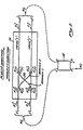
- phase errors may be more fully understood through reference to Figure 2, which depicts a conceptual model of the two orthogonal polarization modes of a single mode fiber. Each polarization mode has a propagation velocity different from that of the other polarization mode. Further, it is assumed that there is coupling of light energy between modes, which may be caused e.g., by variations or perturbations in the principal axes of birefringence of the fiber. Such coupling of energy will be referred to herein as "cross coupling.”
- the conceptual fiber model of Figure 2 will be utilized to represent the sensing loop 16 ( Figure 1).
- the counterpropagating waves Wi, W 2 are schematically represented as being coupled, by the coupler 14, to the loop 16, by the dashed arrows.
- the two polarization modes of the single mode optical fiber are schematically represented in Figure 2 by a first line, connecting a pair of terminals C' and D', and a second line, parallel to the first line, connecting a second pair of terminals C" and D".
- the terminals C', and C" on the left side of Figure 2 correspond to the port C of the coupler 14, while the terminals D' and on the right side of Figure 2 correspond to the port D of the coupler 14.
- the above mentioned first and second lines connecting the terminals will be used to represent arbitrary modes i and j, respectively, of the fiber loop 16.
- Cross coupling between the modes i and is represented by a pair of lines, labeled "Branch 1 and "Branch 2", respectively.
- Branch 1 represents cross coupling between the terminals C" and D' while branch 2 represents cross coupling between terminals C' and D".
- the intersection of branch 1 with branch 2, designated by the reference numeral 50, will be referred to as the "coupling center”. It will be understood that no coupling exists between the two branches 1 and 2.
- the coupling center 50 is shown as being offset from the center of the fiber loop 16 to illustrate that the coupling between the polarization modes is not uniform along its length. Therefore, cross coupled light will travel a longer path in one of the modes than the other, yielding a nonrotationally induced phase difference therebetween.
- the fiber birefringence being environmentally sensitive, varies with time, thus making the optical paths travelled by the cross-coupled light also time varying.
- the wave of W 1 is coupled to the fiber loop 16 so that the modes i and j are launched with electric field amplitudes Et and EJ respectively.
- the wave W 2 is coupled to launch each of the modes i and j with electric field amplitudes E - i and Ej respectively.
- the plus (+) and minus (-) superscripts designate the direction of propagation, the clockwise direction about the loop 16 being designated by the plus (+) sign, and the counterclockwise direction around the loop 16 being designated by the minus (-) sign.
- each electric field is divided into two components, namely, a "straight through” component, designated by the subscript "s", and a "cross coupled” component, designated by the subscript "c".
- Et is divided into a straight through component E + is which remains in mode i during traverse of the loop 16, and a cross coupled component E + jc , which is cross coupled to mode j during traverse of the loop 16.
- E - i is divided into components E - is and E - jc ;
- EJ is divided into component Etc and E + js ; and
- E - j is divided into components E - js and E - ic
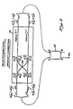
- the light at terminal C' will comprise components E - is and E - ic ; the light at terminal C" will comprise component E - js and E jc ; the light at terminal D', will comprise components E + is and E + ic ; and the light at terminal D" will comprise components E + js and E + jc , as shown in Figure 3.
- These 8 electric field components are combined by the coupler 14 to form the optical output signal W o .
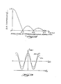
- the 8 dc terms are shown in Figure 4 as a single vector sum, labeled I dc
- the 28 interference terms are shown in Figure 4 as a single vector, labeled I i .
- These vectors I dc and I i are plotted in a complex plane.
- the phase-dependent vector I i rotates, in the manner of a phasor, through an angle equal to the rotationally reduced phase difference ⁇ s due to the Sagnac effect.
- the projection of the interference vector I i upon the real axis, when added to the vector I dc yields the total optical intensity I DET of the optical output signal W o , as measured by the detector 20 ( Figure 1).
- this optical intensity I DET is plotted as function of the Sagnac phase difference ⁇ s , as illustrated by the curve 52.
- phase error ⁇ e causes the phasor I i to be rotated, e.g., from the position shown in solid lines to the position shown in dotted lines in Figure 4. This results in the curve 52 of Figure 5 being translated by an amount ⁇ e , e.g., from the position shown in solid lines to the position shown in dotted lines in Figure 5.
- Group II includes those pairs of electric field components which are in different modes, after traverse of the loop 16, regardless of the mode in which they originated.
- field component E + is , in mode i is paired with component E - jc , in mode j. Since the modes, i and j are orthogonal, and since the electric fields of orthogonal modes do not interfere, there will be no interference between the terms in Group II. It is important to recognize, however, that the field patterns of the paired electric fields in Group II are only orthogonal in a "global" sense. That is, the entire field patterns must be spatially averaged over a plane normal to the fiber axis to eliminate interference.
- the present invention utilizes a detector 20 which has a surface area sufficiently large to capture substantially all of the light exiting the end of the fiber 19, as discussed above.
- the input light W i in the intermediate portion 13 of the birefringent fiber 11 has optical fields that can be represented as a 1 ( ⁇ ) and a 2 ( ⁇ ) for the i polarization mode and the polarization mode, respectively.
- the light returning to the intermediate portion 13 of the birefringent fiber 11 after traversing the loop portion 16 in the clockwise and counterclockwise direction can be represented as: where is the input optical field to the sensing loop portion 16, is the transfer matrix corresponding to the clockwise propagation in the single-mode, high-birefringence fiber 11 including the effects of the second directional coupler 14 that forms the loop portion 16, 2 ⁇ s is the Sagnac phase shift, and the indices 1, 2 refer to the fiber polarization modes i and j, respectively.
- G ccw ( ⁇ ) G T cw ( ⁇ ), that is, the clockwise and counterclockwise transfer matrices are the transposes of each other.
- the output signal of the gyroscope for a quasi-monochromatic source 10 is the phase difference between E cw ( ⁇ ) and E ccw ( ⁇ ), that is, where the dagger (t) indicates the hermitian conjugate and arg ⁇ E + c cw ( ⁇ )E cw ( ⁇ ) ⁇ is the phase of the complex number E) cw ( ⁇ )E cw ( ⁇ ). With zero rotation, the phase error is given by: where the dependence on the optical frequency ⁇ is made implicit for simplicity.
- Amplitude type phase error ( ⁇ amp ) depends on the relative phase of the input field components a 1 and a 2 , and arises from the coherent interference of field components that were orthogonally polarized at the input of the loop and were brought into the same polarization mode by an odd number of cross coupling centers. Amplitude type phase errors correspond to the Group I pairs of electric field components described above. Intensity type phase errors ( ⁇ int ) are due to interference between waves originally in the same polarization mode that cross couple into the other mode, and depend upon the optical power difference between the two polarization modes, regardless of their relative phase. Intensity type phase errors correspond to the Group III pairs of electric field components described above.
- the Group I amplitude type phase errors include phase errors caused by those pairs of field components which originated in different modes, but which are in the same mode upon reaching the coupler 14, after traversing the loop 16.
- the first of Group I pair of components comprises a straight-through component E + is , which originated in mode i and remained in mode i during traverse of the loop 16, and a cross coupled component E + ic which originated in mode j but was cross coupled to mode i during traverse of the loop 16. Ordinarily, these components would interfere with each other, as described in reference to equation (1).
- Group 1 errors arise from the coherent interference of field components that were orthogonally polarized at the input of the loop 16 and were brought into the same polarization mode by an odd number of coupling centers in the loop 16. If the phase difference between these light wave components is random, interference between the light wave components will be averaged to zero in the detector 20. Accordingly, Group I interference terms can be eliminated by insuring that, upon reaching the coupler 14, and thus the loop 16, the light in each mode is incoherent, i.e., random in phase with respect to the light in the other mode.
- the interference between, e.g., the components Et s and E + ic will be averaged to zero in the detector is 20.
- the interference between the remaining components, e.g., Et s and E - ic ; Ej s and E + ic ; etc. will be averaged to zero.
- Such incoherence between Group I components is achieved in part in the present invention by using the high birefringence fiber 11 in combination with the short coherence length light source 10.
- the birefringence of the fiber 11 and the coherence length of the source 10 should be selected such that there is at least one "fiber coherence length” or "depolarization length” between the source 10 and the coupler 14.
- fiber coherence length or “depolarization length” is defined as the length of fiber required for the optical path length difference between the two polarization modes to equal one coherence length of the light source 10.
- the fiber coherence length is equal to the coherence length of the source 10 divided by the difference in the refractive indices of the two polarization modes. Accordingly, by utilizing a sufficiently short coherence length source 10, in combination with a sufficiently high birefringence fiber 11, interference between the components listed in Group I and thus, phase errors caused by such interference, may be eliminated. This is accomplished by including an uncorrelating segment 58 in the intermediate Portion 13 of the birefringent fiber 11 between the first directional coupler 12 and th second directional coupler 14 to assure that at least one fiber coherence length exists between the source 10 and the second directional coupler 14.
- optical path lengths of the fiber modes may be measured or calculated, using modal dispersion data provided by the manufacturer of the fiber.
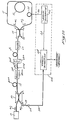
- the present invention further includes a birefringent modulator 60 that is disposed between the port C of the first directional coupler 12 and the port A of the second directional coupler 14, as illustrated in Figure 6.
- the birefringent modulator 60 is located between the uncorrelating segment 58 and the port A of the second directional coupler 14.
- FIG. 7 The construction of an exemplary birefringent modulator 60 is illustrated in Figure 7 wherein a portion of the birefringent fiber 11 is positioned between two quartz slabs 62 and 64.
- the birefringent fiber 11 is preferentially positioned with respect to the surfaces of the two quartz slabs 62 and 64 such that the fast axis of the birefringent fiber 11 is perpendicular (i.e., normal) to the two surfaces.
- Figure 8 is a cross-section of the birefringent modulator 60 taken along the lines 8-8 in Figure 7.
- the axes of birefringence of the birefringent fiber 11 are shown as phantom lines, with the fast axis labelled as "f” and the slow axis labelled as "s.”
- the quartz slabs 62 and 64 are glued to the birefringent fiber 11 to create a sandwich, thereby maintaining the birefringent axes in that position.
- the quartz slabs 62 and 64 are then clamped against a piezoelectric transducer 66.
- the clamping is provided by conventional means and is represented by a pair of force vectors "F."
- the piezoelectric transducer 66 is connected via a pair of interconnection wires 70 and 72 to a modulation source 74.
- the modulation source 74 is advantageously an electrical signal generator for producing a triangular wave output at a frequency f BMOD of approximately 100 hertz.
- a time- varying force is applied to the birefringent fiber 11 via the quartz slabs 62 and 64.
- the time-varying force produces a modulation in the birefringence of the birefringent fiber 11 through the well-known elasto-optic effect.
- This modulation of the birefringence induces modulation in the relative phase between the two polarization modes in the birefringent fiber 11.
- Squeezing the birefringent fiber 11 along the fast axis (f in Figure 8) increases the birefringence and, as a consequence, the orientation of the resultant birefringence is less sensitive to misalignments between the applied stress and the fiber principal axes.
- the signal applied to the piezoelectric transducer 66, and thus the modulation applied to the birefringent fiber 11, is deterministic, and, in the embodiment described herein, is a triangular waveform, as set forth above.
- the birefringent modulator 60 can be formed directly on the fiber 11, as illustrated herein, or it can be formed on a separate fiber and spliced into the rotation sensor system by conventional splicing means.
- Figure 9 is a graph of amplitude phase error ( ⁇ offset ) on the vertical scale caused by an environmental condition, such as temperature.
- the horizontal scale is a function of temperature, 4'temp.
- the birefringence of the birefringent fiber 11 will vary as the temperature of the fiber 11 varies.
- the change in birefringence causes an amplitude type phase error that changes in accordance with the birefringence and the amplitude type phase error is thus a function of the temperature.
- the amplitude phase error varies as the sine of the temperature function ⁇ temp as follows:
- the amplitude error A ⁇ offset will vary from 0 to A 4) am p( max ) to 0 to - ⁇ amp(max) and back to 0, as illustrated in Figure 9.
- the function of temperature (4'temp) is itself a complex function of temperature and that Figure 9 is a graph of 4'temp rather than temperature.
- other environmental conditions, such as pressure add further complexity to the determination of the phase error.
- the present invention utilizes the birefringence modulator 60 to superimpose a known timevarying phase error on the environmentally-induced phase error to cause the time average of the phase error to become substantially equal to zero.
- Figures 10 and 11 illustrate the effect of the birefringent modulator 60 of Figure 7 on the birefringent fiber 11.
- the triangular waveform input to the piezoelectric transducer 66 of the birefringent modulator 60 is illustrated in Figure 10, with its amplitude, labelled ⁇ BMOD , on the vertical axis shown as a function of time on the horizontal axis.
- the phase error i.e., the amplitude type error
- the phase error induced by the birefringent modulator 60 varies sinusoidally with the amplitude of the triangular waveform as illustrated in Figure 11, and in accordance with the following Equation:
- the amplitude of the triangular waveform input is selected so that as the waveform varies from its minimum magnitude (shown as 0) to its maximum magnitude (shown as 2 ⁇ ), the phase error, shown as the amplitude error A ⁇ offset , induced by the birefringent modulator 60, varies sinusoidally from 0 to A ⁇ amp(max) , then to 0, to - ⁇ amp(max) , and back to 0.
- the amplitude error will again vary sinusoidally and will be the mirror image of the amplitude error caused by the increasing portion of the triangular waveform.
- the effect of the birefringence modulator 60 was illustrated alone without considering the combined effect of the environmentally-induced phase error.
- the environmentally-induced phase error and the phase error caused by the birefringence modulator 60 are shown in combination to illustrate the effect of the birefringence modulator 60 in reducing or eliminating the effect of the environmentally-induced phase errors.
- the phase error, A ⁇ offset is illustrated for a temperature such that the function of temperature, *temp is approximately ⁇ /4 ( ⁇ temp1 in Figure 10) thus causing an amplitude type phase error of approximately 0.707 ⁇ amp(max) .
- the total amplitude type phase error is a sinusoidal function of the temperature function ⁇ temp and the modulation function ⁇ BMOD as follows: Although the temperature may be varying and thus the temperature function ⁇ temp may be varying, the variation with respect to time is very slow in comparison with the modulation function ⁇ BMOD and is thus shown as a constant magnitude represented by a dashed line 80 in Figure 12.
- the amplitude type phase error is thus shown as beginning at the amplitude represented by the dashed line 80 and then varying sinusoidally in accordance with a waveform 82 as the triangular waveform of the birefringence modulation increases to its maximum magnitude, as illustrated in Figure 10.
- the sinusoidal waveform 82 When the triangular waveform reaches its maximum magnitude, the sinusoidal waveform 82 will have completed one cycle and will return to the initial magnitude, as shown at the location 84 in Figure 12. Thus, the average magnitude of the amplitude type phase error during the time required for the magnitude of the triangular waveform to increase from its minimum to its maximum magnitude is zero. As further illustrated in Figure 12, the average magnitude of the amplitude type phase error during the time required for the magnitude of the triangular waveform to decrease from its maximum magnitude to its minimum magnitude is also zero.
- the modulation frequency f BMOD is selected to be much greater than the detection bandwidth of the detection electronics 22 (e.g., 100 Hz versus 1 Hz) so that only the average magnitude of the amplitude type phase error induced by the birefringence modulator 60 is detectable.
- the modulation amplitude for the triangular waveform driving the birefringence modulator 60 is selected to be an integer multiple of 2 1T , the average amplitude type phase error will be substantially equal to zero.
- the amplitude of the triangular waveform is selected to be an integer multiple of 2 1T .
- the effect of inaccuracies in the modulation amplitude can be reduced.
- Figure 14 illustrates the effect of the modulation amplitude on the correction of the amplitude type phase errors.
- the vertical scale represents the amplitude type phase error with the magnitude normalized so that 1.0 represents the maximum amplitude type phase error (i.e., ⁇ amp(max) ) at a particular temperature with no birefringence modulation applied.
- the horizontal scale represents the magnitude of the birefringence modulation applied.
- the amplitude type phase error decreases as the amplitude of the birefringence modulation is increased towards 2 ⁇ .
- the amplitude type phase error is at a minimum.
- the amplitude type phase error increases until it reaches another maximum, and then decreases to a minimum at a modulation amplitude of 4 ⁇ .
- the foregoing repeats with amplitude type phase error minima at even multiples of 1T . As illustrated, each successive maximum is smaller than the preceding maximum.
- a is the fraction of the optical power that is coupled between the i and j modes per unit of fiber length (e.g., km);
- L is the length of the fiber loop 16 (e.g., in km);
- ⁇ s is the rotationally induced, Sagnac phase difference between the two components;
- ⁇ p is the total accumulated phase for light that is cross coupled from one mode to another between the terminals C" and D';
- ⁇ q is the total accumulated phase for light that is cross coupled from one mode to the other between terminals C', and D".
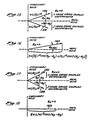
- the vector 160 is inclined from the real axis by a phase angle ⁇ e (III), which represents the non-rotationally induced phase error contribution to the total phase error ⁇ e ( Figure 4) that is due to interference between the components of Group III.
- the projection of the vector 160 upon the real axis is simply the algebraic sum of the two interference terms (11) and (12):
- the effect of variations in the quantity ⁇ p - ⁇ q can be distinguished from the rotationally induced Sagnac phase difference as may be more fully understood through reference to Figures 17 and 18, which show the effect, upon the resultant vector 160, of making the vectors 156 and 158 equal in magnitude, and through reference to Figure 19, which shows the optical intensity measured by the detector 20 when the phase error is zero. It will be seen that, regardless of the value of the quantity ⁇ p - ⁇ q , the resultant vector 160 will always be directed along the real axis, and thus, the direction of the vector 160 is independent of variations in the quantity ⁇ p - ⁇ q .
- the present invention provides an apparatus for substantially reducing or eliminating the Group III intensity type phase errors without equalizing the optical intensities in the loop portion 16. That portion of the present invention that reduces or eliminates the Group III intensity type errors is illustrated in Figure 20.
- the embodiment of Figure 20 includes an uncorrelating segment 200 of the birefringent fiber 11.
- the uncorrelating segment 200 is optically connected to the port C of the first directional coupler 12.
- the segment 200 can be advantageously formed into a loop or the like for compactness.
- the length of the uncorrelating segment 200 is advantageously selected to be greater than the fiber coherence length (depolarization length) of the birefringent fiber 11 so that any portion of the optical signal propagating in the first polarization mode (e.g., mode i) becomes uncorrelated (i.e., incoherent) with any portion of the optical signal propagating in the second polarization mode (e.g., mode j).
- the length of the uncorrelating segment 200 may be advantageously in the range of 4-5 meters.
- the embodiment of Figure 20 further includes a birefringence modulator 202 formed on the intermediate portion 13 of the birefringent fiber 11 after the uncorrelating segment 200.
- the birefringence modulator 202 operates in the same manner as the birefringence modulator 66, described above to further uncorrelate the light in the two polarization modes.
- the intermediate portion 13 of the fiber 11 is cut to form a first splice end 206 and a second splice end 208.
- the first splice end 206 and the second splice end 208 are rotated by 45 ° with respect to each other and are then optically interconnected by conventional means.
- the axes of birefringence of the optical fiber 11 are shifted by 45 at the splice represented by the reference numeral 204.
- the axes of birefringence of the first splice end 206 are oriented at an angle of 45 with respect to the axes of birefringence of the second splice end 208.
- the 45 splice serves to equalize the optical power in the two polarization modes of the fiber 11, such that, upon exiting the splice, each mode carries substantially the same optical power.
- the birefringent fiber is optically connected to a polarizer 220.
- the polarizer is a conventional polarizer having a transmission axis and a blocking axis, corresponding to two axes of polarization.
- the polarizer 220 may be advantageously constructed in accordance with U.S. Patent No. 4,386,822.
- the polarizer 220 will pass substantially all of the light that is propagating in a polarization mode that is aligned with the transmission axis of the polarizer and will block substantially all of the light that is propagating in a polarization mode that is aligned with the blocking axis of the polarizer.
- the light incident on the polarizer is evenly divided between the two polarization modes.
- the polarizer is aligned to block the light in one of these modes and to pass the light in the other of the modes.
- the ratio of the intensity of the light passed by the polarizer 220 along the transmission axis to the intensity of the light passed by the polarizer 220 along the blocking axis is referred to as the extinction ratio.
- a polarizer having an extinction ratio of 30-40 dB, or better, is advantageously used.
- the intensity of the light passed by the blocking axis of the polarizer 220 will be approximately 0.001 to 0.0001 times, or less, the intensity of the light passed by the transmission axis of the polarizer 220.
- the polarizer is connected to the birefringent fiber 11 so that the transmission axis of the polarizer 220 is aligned with one of the two birefringent axes of the second splice end 208.
- the birefringent fiber 11 After passing through the polarizer 220, the birefringent fiber 11 is optically connected to the port A of the second directional coupler 14, as in Figure 1.
- the loop portion 16 of the rotation sensor is optically connected between the port C and the port D of the second directional coupler 14, and is advantageously constructed the same as was described in Figure 1.
- the uncorrelating segment 200, the birefringence modulator 202, the 45 splice 204, and the polarizer 220 accomplish the same effect as precisely equalizing the optical intensities of the two modes within the fiber loop 16.
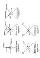
- Figures 21A-21E illustrate the operation of the present invention when substantially all of the light incident upon the splice 204 at the first splice end 206 is in one of the two polarization modes (e.g., in mode j). This could occur, for example, when the source 10 is a polarized source and the birefringent fiber 11 has its axes aligned with the polarization axes of the source 10. The light would then be input to the fiber 11 in only one polarization mode, and the birefringent fiber 11 and the first directional coupler 12 would maintain the light in the original polarization mode.
- the optical intensity is thus illustrated in Figure 21 A as being solely in mode j of the birefringent fiber 11 at the splice end 206 at the splice 204, as represented by an intensity vector 230.
- Figure 21 B represents the effect of the 45 ° splice 204 on the light propagating in the birefringent fiber 11.
- the optical intensity originally propagating in the mode j polarization axis of the first splice end 206 is divided equally between the two polarization axes of the birefringent fiber 11 as represented by a mode j vector 240 along the mode j' polarization axis (i.e., axis of birefringence) of the second splice end 208, and a mode i vector 242 along the mode i' polarization axis of the second splice end 208.
- the optical intensity necessarily divides equally between the two polarization modes because of the 45 splice 204.
- the two intensity vectors 240 and 242 are shown as having substantially equal lengths.
- the light passed by the polarizer 220 in the j' polarization mode is represented by an intensity vector 250 in Figure 21 C
- the light passed by the polarizer 220 in the i' polarization mode is represented by an intensity vector 252 in Figure 21 C.
- the intensity vector 252 is approximately 0.001 times the length of the intensity vector 250, assuming a polarization extinction ratio of 30 dB, as set forth above.
- the sizes of the vectors 250 and 252 are, of course, not to scale.
- the light in each of the polarization modes is divided substantially equally by the second directional coupler 14 and caused to propagate around the loop portion 16 of the birefringent fiber 11, as described above.
- optical energy is coupled between the two polarization modes.
- the optical energy coupled from the j' polarization mode to the i' polarization mode in the clockwise direction is represented by the designator E + ic as before.
- the optical energy coupled from the i' polarization mode to the j' polarization mode in the clockwise direction is represented by the designator E + jc .
- the designators E - ic and Ej e represent the corresponding coupled energy in the counterclockwise direction.
- the light coupled to the i' mode has a greater intensity, as represented by the longer intensity vector 262.
- the vectors 260 and 262 are not to scale, and the intensity vector 262 represents an intensity 1000 times greater than the intensity represented by the intensity vector 260.
- a similar relationship holds for the energy coupled to the two modes in the counterclockwise direction.
- the light energy After being recombined in the second directional coupler 14, the light energy again passes through the polarizer 220, in the opposite direction back towards the splice 204.
- the polarizer 220 is bidirectional and thus has the same effect as before on the light incident to it in the two polarization modes. This effect is illustrated in Figure 21 E.
- the polarizer 220 passes substantially all of the light incident to it in the j' polarization mode and thus will pass substantially all of the optical energy E + jc and Ej e that was coupled from the i' mode to j in the loop portion 16.
- the light passed by the polarizer 220 in the j' polarization mode is represented by an intensity vector 270.
- the polarizer 220 will pass only 0.001 times the intensity of the light incident to it in the i' polarization mode and thus will pass only 0.001 times the optical energy E + ic and Ej e that was coupled from the j' mode to the i' mode in the loop portion 16.
- the intensity of the light passed by the polarizer 220 in the i' polarization mode is represented by an intensity vector 272. Since the intensity of the light coupled to the i' mode is 1000 times the intensity of light coupled to the j' mode, the effect of passing back through the polarizer 220 is to equalize the coupled light intensities in the two modes. Thus, the i' intensity vector 272 is illustrated as being equal in length to the intensity vector 270.
- the j' intensity vector 270 and the i' intensity vector are uncorrelated because of the long length of the portion of the birefringent fiber 11 comprising the loop portion 16.
- the resulting light adds in intensity only without respect to phase.
- the resulting equal intensities in the two polarization modes effectively eliminates the intensity type phase errors (i.e., mode III phase errors) caused by unequal light intensities in two polarization modes.
- Figures 22A-221 illustrate that the present invention effectively equalizes the coupled power in the two modes even when the light incident to the 45 splice is in both polarization modes. It further illustrates the beneficial effect of the segment 200 of the birefringent fiber 11 and the birefringence modulator 202 in causing the light to become uncorrelated before reaching the 45 splice.
- the light incident to the first splice end 206 comprises optical energy in both the j polarization mode and the i polarization mode.
- the optical energy in the second splice end 208 can be considered as comprising four portions.
- the first two portions are illustrated in Figure 22B wherein the optical energy originally in the i polarization mode, represented by a phantom intensity vector 282', in Figure 22A, is divided equally between the j' polarization mode and the i' polarization mode of the second splice end 208.
- This division of the optical energy is represented by a j' intensity vector 290 and an i' intensity vector 292 in Figure 22B.
- Figure 22C illustrates the division of the optical energy originally in the j polarization mode, as represented by a phantom intensity vector 280', into equal portions in the j' polarization mode, represented by an intensity vector 294, and in the i' polarization mode, represented by an intensity vector 296. Since the light originally in the i polarization mode was uncorrelated with the light originally in the j polarization mode because of the effect of the uncorrelating segment 200 and the birefringence modulator 202, the light represented by the j' intensity vector 290 in Figure 22B does not interfere with the light represented by the j' intensity vector 294 in Figure 22C.
- the light represented by the i' intensity vector 292 in Figure 22B does not interfere with the light represented by the i' intensity vector 296 in Figure 21 C.
- the intensity vectors 290 and 292 in Figure 22B can be considered separately from the intensity vectors 294 and 296 in Figure 21 C.
- Figure 22D illustrates the effect of the polarizer 220 on the light represented by the intensity vectors 290 and 292 of Figure 22B (i.e., the light that was originally in the i polarization mode of the first splice end 206).
- substantially all of the light in the j' polarization mode is passed by the polarizer 220, as represented by an intensity vector 300, and only 0.001 times as much intensity in the i' polarization mode is passed, as represented by a smaller intensity vector 302 (unscaled).
- the intensities of the light that was originally in the j polarization mode of the first splice end 206 that is passed by the polarizer 220 is illustrated in Figure 22E wherein an intensity vector 304 represents the light in the j' polarization mode and an intensity vector 306 represents the light in the i' polarization mode. Again, the intensity of the light represented by the i' intensity vector 306 is 0.001 times the intensity of the light represented by the j' intensity vector 304.
- Figure 22F illustrates a j' intensity vector 310 that represents the light coupled from the i' polarization mode to the j' polarization mode in the loop portion 16, and an intensity vector 312 represents the light coupled from the j' polarization mode to the i' polarization mode in the loop portion 16.
- the i' intensity vector 312 represents an intensity that is 1000 times the intensity represented by the j' intensity vector 310.
- Each of the intensity vectors 310 and 312 in Figure 22F represents light that was originally in the i polarization mode in the first splice end 206.
- An intensity vector 320 in Figure 22H represents light in the j' polarization mode that was represented by the j' intensity vector 310 in Figure 22F and that has had no substantial attenuation by the polarizer 220.
- a vector 322 in Figure 22H represents light in the i' polarization mode that was represented by the i' intensity vector 312 in Figure 22F and that has been attenuated by a factor of 1000 by the polarizer 220.
- the intensity represented by the i' intensity vector 322 was 1000 times the intensity represented by the j' intensity vector 310, the i' intensity vector 322 and the j' intensity vector 320 are substantially equal.
- a j' intensity vector 324 in Figure 221 represents the substantially unattenuated light in the j' polarization mode that was represented by the j' intensity vector 314 in Figure 22G
- an i' intensity vector 326 in Figure 221 represents the intensity of light in the i' polarization mode that has been attenuated by a factor of 1000 in passing through the polarizer 200.
- the i' intensity vector 326 represents an intensity substantially equal to the intensity represented by the j' intensity vector 324.
- the intensity vectors 320 and 322 in Figure 21 H represent light that is uncorrelated with the light represented by the intensity vectors 324 and 326, the light represented by the two pairs of intensity vectors does not interfere and the two pairs of intensities add without respect to the phase of the light. Since the intensities in the i' polarization modes are equal to the intensities in the j' polarization modes, the effect is the same as if the optical signals were input into the loop with the intensities in the two polarization modes substantially equal. Thus, there will be substantially no intensity type phase error (i.e., group III phase error) caused by variations in intensity in the two polarization modes.
- group III phase error i.e., group III phase error
- the present invention will provide the effect described above irrespective of the relative amount of optical power in the two polarization modes so long as the light in the two polarization modes is uncorrelated.
- the function of the birefringence modulator 202 is to assure that the two polarization modes are uncorrelated.
- Figure 23 illustrates the rotation sensor of Figure 6 combined with the rotation sensor of Figure 20 to accomplish the reduction of the amplitude type phase errors (Group I) and the intensity type phase errors (Group III) through use of the uncorrelating segment 58 and the birefringence modulator 60 in combination with the uncorrelating fiber segment 200, the birefringence modulator 202, the 45 splice 204, and the polarizer 220.
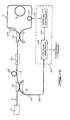
- FIG 24 illustrates an alternative embodiment of the present invention in which an additional birefringence modulator 500 is positioned on the loop portion 16 of the birefringent fiber 11.
- the loop birefringence modulator 500 is located in the loop portion 16 at a location that is asymmetrical with respect to the center of the loop portion 16.
- the loop birefringence modulator 500 is shown located closer to the port C of the second directional coupler 14 than to the port D of the second directional coupler 14.
- the function of the loop birefringence modulator 500 is to induce a time-varying birefringence that causes a time-varying phase shift between the lightwaves travelling in the two polarization modes, as described above.
Landscapes
- Physics & Mathematics (AREA)
- Engineering & Computer Science (AREA)
- Optics & Photonics (AREA)
- Electromagnetism (AREA)
- Power Engineering (AREA)
- General Physics & Mathematics (AREA)
- Radar, Positioning & Navigation (AREA)
- Remote Sensing (AREA)
- Gyroscopes (AREA)
- Light Guides In General And Applications Therefor (AREA)
Claims (16)
Applications Claiming Priority (2)
| Application Number | Priority Date | Filing Date | Title |
|---|---|---|---|
| US909741 | 1986-09-19 | ||
| US06/909,741 US4881817A (en) | 1986-09-19 | 1986-09-19 | Fiber optic rotation sensor utilizing high birefringence fiber and having reduced intensity type phase errors |
Publications (3)
| Publication Number | Publication Date |
|---|---|
| EP0262825A2 EP0262825A2 (fr) | 1988-04-06 |
| EP0262825A3 EP0262825A3 (en) | 1990-08-08 |
| EP0262825B1 true EP0262825B1 (fr) | 1992-10-28 |
Family
ID=25427753
Family Applications (1)
| Application Number | Title | Priority Date | Filing Date |
|---|---|---|---|
| EP87308043A Expired EP0262825B1 (fr) | 1986-09-19 | 1987-09-11 | Détecteur de rotation fibre-optique avec une fibre de biréfringence haute et une erreur de phase d'intensité faible |
Country Status (5)
| Country | Link |
|---|---|
| US (1) | US4881817A (fr) |
| EP (1) | EP0262825B1 (fr) |
| JP (1) | JPH07104166B2 (fr) |
| CA (1) | CA1276274C (fr) |
| DE (1) | DE3782393T2 (fr) |
Cited By (1)
| Publication number | Priority date | Publication date | Assignee | Title |
|---|---|---|---|---|
| CN105486425A (zh) * | 2016-01-12 | 2016-04-13 | 安徽大学 | 一种大量程的温度绝对值测量方法及测量装置 |
Families Citing this family (33)
| Publication number | Priority date | Publication date | Assignee | Title |
|---|---|---|---|---|
| US5153676A (en) * | 1983-04-26 | 1992-10-06 | The Board Of Trustees Of The Leland Stanford Junior University | Apparatus and method for reducing phase errors in an interferometer |
| US5120130A (en) * | 1983-04-26 | 1992-06-09 | The Board Of Trustees Of The Leland Stanford Junior University | Apparatus and method for reducing phase errors in an interferometer |
| JPH02173518A (ja) * | 1988-12-27 | 1990-07-05 | Hitachi Cable Ltd | 光ファイバ回転角速度センサ |
| US5037205A (en) * | 1989-04-19 | 1991-08-06 | Litton Systems, Inc. | Integrated optic interferometric fiber gyroscope module and method |
| US5108183A (en) * | 1989-08-31 | 1992-04-28 | The Board Of Trustees Of The Leland Stanford Junior University | Interferometer utilizing superfluorescent optical source |
| US5046848A (en) * | 1989-09-08 | 1991-09-10 | Mcdonnell Douglas Corporation | Fiber optic detection system using a Sagnac interferometer |
| FR2662245B1 (fr) * | 1990-05-18 | 1994-05-20 | Photonetics | Dispositif de mesure a fibre optique, gyrometre, centrale de stabilisation et capteur de courant ou de champ magnetique. |
| US5157461A (en) * | 1990-06-14 | 1992-10-20 | Smiths Industries Aerospace & Defense Systems Inc. | Interface configuration for rate sensor apparatus |
| US5106193A (en) * | 1990-08-09 | 1992-04-21 | The Board Of Trustees Of The Leland Stanford Junior University | Optical waveguide amplifier source gyroscope |
| US5185749A (en) * | 1990-09-18 | 1993-02-09 | The Board Of Trustee Of The Leland Stanford Junior University | Large signal three-level superfluorescent fiber sources |
| US5177562A (en) * | 1990-09-18 | 1993-01-05 | The Board Of Trustees Of The Leland Stanford Junior University | Stability compensated broadband source and fiber interferometer |
| US5137360A (en) * | 1990-12-21 | 1992-08-11 | Honeywell Inc. | Fiber optic gyro with a source at a first wavelength and a fiber optic loop designed for single mode operation at a wavelength longer than the first wavelength |
| US5327213A (en) * | 1991-11-14 | 1994-07-05 | Honeywell Inc. | Configuration control of mode coupling errors |
| US5377283A (en) * | 1992-05-29 | 1994-12-27 | Honeywell Inc. | Configuration control of mode coupling errors |
| US5397891A (en) * | 1992-10-20 | 1995-03-14 | Mcdonnell Douglas Corporation | Sensor systems employing optical fiber gratings |
| US5365337A (en) * | 1992-10-28 | 1994-11-15 | Smiths Industries Aerospace & Defense Systems, Inc. | Method and apparatus for compensating for the residual birefringence in interferometric fiber-optic gyros |
| US5598489A (en) * | 1994-07-27 | 1997-01-28 | Litton Systems, Inc. | Depolarized fiber optic rotation sensor with low faraday effect drift |
| US5653537A (en) * | 1995-03-17 | 1997-08-05 | Ircon, Inc. | Non-contacting infrared temperature thermometer detector apparatus |
| US5655035A (en) * | 1995-11-16 | 1997-08-05 | Alliedsignal Inc. | Differential fiber optic angular rate sensor for minimizing common mode noise in the sensor output |
| US5894531A (en) * | 1997-03-11 | 1999-04-13 | Karta Technology, Inc. | Method and apparatus for detection of ultrasound using a fiber-optic interferometer |
| US5812270A (en) * | 1997-09-17 | 1998-09-22 | Ircon, Inc. | Window contamination detector |
| GB9726191D0 (en) | 1997-12-11 | 1998-02-11 | Philips Electronics Nv | Ion implantation process |
| US6115124A (en) * | 1998-12-10 | 2000-09-05 | Litton Systems, Inc. | Method for measurement of PNR bias error in an interferometric fiber optic gyroscope (IFOG) |
| US7269190B2 (en) * | 2002-10-02 | 2007-09-11 | The Board Of Trustees Of The Leland Stanford Junior University | Er-doped superfluorescent fiber source with enhanced mean wavelength stability |
| CN101639383B (zh) * | 2008-12-25 | 2010-12-29 | 北京理工大学 | 一种主被动结合的移相干涉波面测量方法 |
| WO2014077735A1 (fr) * | 2012-11-13 | 2014-05-22 | Logozinski Valery Nikolaevich | Gyroscope à fibre optique |
| JP6260911B2 (ja) * | 2013-02-01 | 2018-01-17 | ザ・ボード・オブ・トラスティーズ・オブ・ザ・リーランド・スタンフォード・ジュニア・ユニバーシティ | 低速光センサ用途のための結合導波路 |
| CN106030318B (zh) | 2013-12-20 | 2020-11-17 | Abb电网瑞士股份公司 | 光纤传感器和方法 |
| US9097526B1 (en) * | 2014-01-17 | 2015-08-04 | Honeywell International Inc. | Systems and methods for a polarization matched resonator fiber optic gyroscope |
| US10094664B2 (en) | 2016-11-23 | 2018-10-09 | Honeywell International Inc. | Apparatus and method for diminishing bias error in resonant fiber optic gyroscopes |
| US10365107B2 (en) * | 2017-08-03 | 2019-07-30 | Honeywell International Inc. | Systems and methods for reducing polarization-related bias errors in RFOGS |
| WO2021178627A1 (fr) * | 2020-03-04 | 2021-09-10 | University Of Georgia Research Foundation, Inc. | Organe de préhension à spirale robotique souple pneumatique doté d'un capteur à fibre optique |
| CN112595307B (zh) * | 2020-10-30 | 2022-09-16 | 西安航天精密机电研究所 | 一种干涉式光纤陀螺光路误差计算方法 |
Family Cites Families (5)
| Publication number | Priority date | Publication date | Assignee | Title |
|---|---|---|---|---|
| DE2901388A1 (de) * | 1979-01-15 | 1980-07-24 | Max Planck Gesellschaft | Verfahren und anordnung zur messung von drehungen mittels des sagnac-effekts |
| DE3006580A1 (de) * | 1980-02-22 | 1981-08-27 | Licentia Patent-Verwaltungs-Gmbh, 6000 Frankfurt | Ringinterferometer |
| DE3049033A1 (de) * | 1980-12-24 | 1982-07-22 | Licentia Patent-Verwaltungs-Gmbh, 6000 Frankfurt | "ringinterferometer" |
| DE3115804A1 (de) * | 1981-04-18 | 1982-11-04 | Licentia Patent-Verwaltungs-Gmbh, 6000 Frankfurt | "ringinterferometer" |
| US4456377A (en) * | 1981-11-06 | 1984-06-26 | The Board Of Trustees Of Leland Stanford Jr. Univ. | Multimode fiber optic rotation sensor |
-
1986
- 1986-09-19 US US06/909,741 patent/US4881817A/en not_active Expired - Lifetime
-
1987
- 1987-09-11 DE DE8787308043T patent/DE3782393T2/de not_active Expired - Lifetime
- 1987-09-11 EP EP87308043A patent/EP0262825B1/fr not_active Expired
- 1987-09-18 JP JP62236057A patent/JPH07104166B2/ja not_active Expired - Lifetime
- 1987-09-18 CA CA000547242A patent/CA1276274C/fr not_active Expired - Lifetime
Cited By (2)
| Publication number | Priority date | Publication date | Assignee | Title |
|---|---|---|---|---|
| CN105486425A (zh) * | 2016-01-12 | 2016-04-13 | 安徽大学 | 一种大量程的温度绝对值测量方法及测量装置 |
| CN105486425B (zh) * | 2016-01-12 | 2018-05-01 | 安徽大学 | 一种温度绝对值测量方法及测量装置 |
Also Published As
| Publication number | Publication date |
|---|---|
| US4881817A (en) | 1989-11-21 |
| JPH07104166B2 (ja) | 1995-11-13 |
| DE3782393D1 (de) | 1992-12-03 |
| JPS6395312A (ja) | 1988-04-26 |
| EP0262825A3 (en) | 1990-08-08 |
| EP0262825A2 (fr) | 1988-04-06 |
| CA1276274C (fr) | 1990-11-13 |
| DE3782393T2 (de) | 1993-05-27 |
Similar Documents
| Publication | Publication Date | Title |
|---|---|---|
| US4881817A (en) | Fiber optic rotation sensor utilizing high birefringence fiber and having reduced intensity type phase errors | |
| US5153676A (en) | Apparatus and method for reducing phase errors in an interferometer | |
| US5644397A (en) | Fiber optic interferometric circuit and magnetic field sensor | |
| EP0084055B1 (fr) | Detecteur rotatif a fibre optique utilisant la lumiere non polarisee | |
| EP0093170B1 (fr) | Detecteur de rotation de fibre optique multi-mode | |
| CN108534798B (zh) | 一种双偏振光纤陀螺中的偏振非互易误差消除方法及双偏振光纤陀螺 | |
| US4634282A (en) | Multimode fiber optic rotation sensor | |
| JP5448745B2 (ja) | 偏光モードにより引き起こされるバイアス誤差が低減されたrfog | |
| US4671658A (en) | Fiber optic rotation sensor utilizing a magnetic shield and an optical isolator | |
| CN102706340B (zh) | 一种干涉式光纤陀螺仪 | |
| CN107328405A (zh) | 一种互易型差动式调频连续波干涉保偏光纤陀螺仪 | |
| US5136667A (en) | Fiber optic gyro | |
| JPH09500734A (ja) | ファラデー効果ドリフトの少ない減偏光された光ファイバ回転センサ | |
| CN114674302B (zh) | 死端光功率回收再利用的双偏振光纤陀螺 | |
| JP3687971B2 (ja) | 干渉計式光ファイバージャイロにおける残留複屈折を補償する方法及び装置 | |
| US5120130A (en) | Apparatus and method for reducing phase errors in an interferometer | |
| JP2002054933A (ja) | 光ファイバジャイロ | |
| JP2751599B2 (ja) | 光フアイバジヤイロ | |
| AU554903B2 (en) | Interferometer with kerr effect compensation | |
| JP2627134B2 (ja) | 光ファイバジャイロ | |
| CN103743392B (zh) | 一种单耦合器双偏振光纤陀螺仪 | |
| JPH02266216A (ja) | 光ファイバジャイロ | |
| JPH02266217A (ja) | 光ファイバジャイロ | |
| JPH10311729A (ja) | 光干渉角速度計 | |
| JPS63159728A (ja) | 光ファイバ圧力センサ |
Legal Events
| Date | Code | Title | Description |
|---|---|---|---|
| PUAI | Public reference made under article 153(3) epc to a published international application that has entered the european phase |
Free format text: ORIGINAL CODE: 0009012 |
|
| AK | Designated contracting states |
Kind code of ref document: A2 Designated state(s): DE FR GB IT |
|
| PUAL | Search report despatched |
Free format text: ORIGINAL CODE: 0009013 |
|
| RHK1 | Main classification (correction) |
Ipc: G01C 19/64 |
|
| AK | Designated contracting states |
Kind code of ref document: A3 Designated state(s): DE FR GB IT |
|
| 17P | Request for examination filed |
Effective date: 19901220 |
|
| 17Q | First examination report despatched |
Effective date: 19910307 |
|
| GRAA | (expected) grant |
Free format text: ORIGINAL CODE: 0009210 |
|
| AK | Designated contracting states |
Kind code of ref document: B1 Designated state(s): DE FR GB IT |
|
| ITF | It: translation for a ep patent filed | ||
| REF | Corresponds to: |
Ref document number: 3782393 Country of ref document: DE Date of ref document: 19921203 |
|
| ET | Fr: translation filed | ||
| PLBE | No opposition filed within time limit |
Free format text: ORIGINAL CODE: 0009261 |
|
| STAA | Information on the status of an ep patent application or granted ep patent |
Free format text: STATUS: NO OPPOSITION FILED WITHIN TIME LIMIT |
|
| 26N | No opposition filed | ||
| REG | Reference to a national code |
Ref country code: FR Ref legal event code: CL |
|
| REG | Reference to a national code |
Ref country code: GB Ref legal event code: IF02 |
|
| PGFP | Annual fee paid to national office [announced via postgrant information from national office to epo] |
Ref country code: FR Payment date: 20060918 Year of fee payment: 20 |
|
| PGFP | Annual fee paid to national office [announced via postgrant information from national office to epo] |
Ref country code: GB Payment date: 20060925 Year of fee payment: 20 |
|
| PGFP | Annual fee paid to national office [announced via postgrant information from national office to epo] |
Ref country code: IT Payment date: 20060930 Year of fee payment: 20 |
|
| PGFP | Annual fee paid to national office [announced via postgrant information from national office to epo] |
Ref country code: DE Payment date: 20061031 Year of fee payment: 20 |
|
| REG | Reference to a national code |
Ref country code: GB Ref legal event code: PE20 |
|
| PG25 | Lapsed in a contracting state [announced via postgrant information from national office to epo] |
Ref country code: GB Free format text: LAPSE BECAUSE OF EXPIRATION OF PROTECTION Effective date: 20070910 |