EP0262839A2 - Schaltungsanordnung zwischen einem schnurlosen und einem normalen Telefon - Google Patents
Schaltungsanordnung zwischen einem schnurlosen und einem normalen Telefon Download PDFInfo
- Publication number
- EP0262839A2 EP0262839A2 EP87308223A EP87308223A EP0262839A2 EP 0262839 A2 EP0262839 A2 EP 0262839A2 EP 87308223 A EP87308223 A EP 87308223A EP 87308223 A EP87308223 A EP 87308223A EP 0262839 A2 EP0262839 A2 EP 0262839A2
- Authority
- EP
- European Patent Office
- Prior art keywords
- unit
- telephone
- switching
- switches
- subscriber line
- Prior art date
- Legal status (The legal status is an assumption and is not a legal conclusion. Google has not performed a legal analysis and makes no representation as to the accuracy of the status listed.)
- Granted
Links
- 238000010586 diagram Methods 0.000 description 9
Images


Classifications
-
- H—ELECTRICITY
- H04—ELECTRIC COMMUNICATION TECHNIQUE
- H04M—TELEPHONIC COMMUNICATION
- H04M9/00—Arrangements for interconnection not involving centralised switching
-
- H—ELECTRICITY
- H04—ELECTRIC COMMUNICATION TECHNIQUE
- H04M—TELEPHONIC COMMUNICATION
- H04M1/00—Substation equipment, e.g. for use by subscribers
- H04M1/72—Mobile telephones; Cordless telephones, i.e. devices for establishing wireless links to base stations without route selection
- H04M1/725—Cordless telephones
-
- H—ELECTRICITY
- H04—ELECTRIC COMMUNICATION TECHNIQUE
- H04M—TELEPHONIC COMMUNICATION
- H04M1/00—Substation equipment, e.g. for use by subscribers
-
- H—ELECTRICITY
- H04—ELECTRIC COMMUNICATION TECHNIQUE
- H04M—TELEPHONIC COMMUNICATION
- H04M19/00—Current supply arrangements for telephone systems
Definitions
- the present invention relates to a cordless or wireless telephone and, more particularly, to a switching system for use between the cordless telephone and an ordinary telephone.
- a cordless telephone comprises a fixed unit which is connected to a telephone network through a subscriber line and a portable unit which is connected to the fixed unit over a radio channel.
- the subscriber of the portable unit communicates with another subscriber through the fixed unit.
- the fixed unit is equipped with a telephone unit including a handset and with a transmitter-receiver for radio communication with the portable unit.
- the telephone unit can communicate with a subscriber of an ordinary telephone connected to the telephone network or with the portable unit.
- the telephone unit and the transmitter-receiver are supplied with power from a common power source. Therefore, if the common power supply is cut off by power failure or any other cause, the telephone unit of the fixed unit will become unusable, and communication with another subscriber will be made impossible even though the telephone unit itself is operable.
- An object of the present invention is to provide a switching system which permits, even when the common power supply to the fixed unit is cut off, its telephone unit to communicate with an ordinary telephone subscriber.
- Another object of the invention is to provide a switching system which permits mutual communication between an ordinary telephone set, the telephone unit of a fixed unit and a portable unit.
- Still another object of the invention is to provide a switching system which permits a command to achieve connection between the above-mentioned three parties to be manually generated at the telephone unit or remotely generated from the portable unit.
- a switching system for use between a cordless telephone and ordinary telephone, comprising a fixed unit and a portable unit connected to each other by radio, a telephone unit provided on the fixed unit side, an internal line applied with a D.C. voltage which is applied to the fixed unit, a first switch responsive to a first switching control signal for selectively connecting the telephone unit to one of a subscriber line and the internal line, the subscriber line being connected to a telephone network, a second switch responsive to a second switching control signal for selectively connecting the fixed unit to one of the subscriber line and the internal line, and switching control means responsive to a switching command signal for generating the first and second switching control signals.
- a switching system for use between a cordless telephone and an ordinary telephone, comprising a fixed unit and a portable unit used in the cordless telephone and radio connected to each other, a power source for supplying electric power to the fixed unit, an internal connection line connected to the power source, a first switch responsive to a first switching signal for selectively connecting the telephone unit to one of a subscriber line connected to a telephone network and the internal connection line, and a second switch responsive to a second switching signal for selectively connecting the fixed unit to one of the subscriber line and the internal connection line.
- a fixed unit 12 connected to public telephone network and a portable unit 13 constitute a cordless telephone.
- the portable unit 13 is comprised of an antenna 7, a transmitter-receiver (including a control unit) 8 and a handset 9.
- the fixed unit 12 connected to another subscriber through the telephone network, comprises a transmitter-receiver (including a control unit) 4, a power source 5 and an antenna 6.
- the power source 5 also supplies power to the telephone unit 3 through an internal connection line 10 and a switch 1.
- the power source 5 may be supplied with commercial A.C. power and regulate it to produce D.C. power.
- Switches 1 and 2 are intended for switching the connection of the telephone unit 3 and the fixed unit 12 to the internal connection line 10 or a subscriber line 11.
- the switches 1 and 2 are controlled either by a manual switching at the telephone unit 3 or a remote switching from the portable unit 13. By switching these switches 1 and 2, mutual communication is made possible between an ordinary subscriber telephone connected to the telephone network, the telephone unit 3 and the portable unit 13.
- both switches 1 and 2 are on the internal connection line 10 side, radio communication is made possible between the portable unit 13 and the telephone unit 3 on the fixed unit 12 side.
- the telephone unit 3 operates on a D.C. voltage from the power source 5.
- the switches 1 and 2 are on the internal connection line 10 side and the subscriber line 11 side, respectively, communication is made possible between the portable unit 13 and another subscriber through the fixed unit 12 and the telephone network.
- the switches 1 and 2 are on the subscriber line 11 side and the internal connection line 10 side, respectively, communication is made possible between the telephone unit 3 on the fixed unit 12 side and another subscriber through the telephone network.
- a D.C. voltage is supplied from the subscriber line 11 to the telephone unit 3.
- the telephone unit 3 Since the telephone unit 3 does not use the power source 5 of the fixed unit 12, it will continue to operate normally even if the power source 5 is cut off by A.C. power failure or the like.
- both switches 1 and 2 are on the subscriber line 11 side, three-party communication is made possible among the portable unit 13, the telephone unit 3 and another subscriber.
- FIG. 1 Now the system of FIG. 1 will be described in detail with reference to FIGS. 2 to 5.
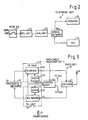
- FIG. 2 is a block diagram of the telephone unit 3 shown in FIG. 1.
- the telephone unit 3 comprises a hook switch 21 for turning the unit on and off, a bell unit 22, a dial unit 23, a speaker 25 and a microphone 26, the last two being connected by way of a speech network 24.
- the speech network 24 branches an input line from the dial unit 23 into lines for the speaker 25 and for the microphone 26.
- the telephone set 3 has the same structure as an ordinary telephone; therefore, no detailed description of its operation will be provided.
- FIG. 3 is a block diagram of the fixed unit 12 shown in FIG. 1.
- a radio signal from the portable unit 13 is picked up by an antenna 48 and supplied through a duplexer 47 to a receiver unit 50 and demodulated thereat.
- the demodulated output is supplied through a speech network 41 to the switch 2 (Fig. 1), a signal from which is supplied through the speech network 41 to a transmitter unit 49 and modulated thereat.
- the modulated output is transmitted via the duplexer 47 and the antenna 48 to the portable unit 13.
- a control unit 46 in order to turn the transmit frequency and the receive frequency to a desired channel, provides a channel designation signal to a synthesizer 43 of the transmitter unit 49 and a synthesizer 45 of the receiver unit 50.
- the control unit 46 also provides various control signals for controlling the portable unit 13 to a transmit driver 42, and switching control signals to the switches 1 and 2.
- the portable unit control signal given to the transmitter unit 49 is demodulated on a carrier wave, and transmitted to the portable unit 13 through a duplexer 29 and an antenna 28.
- the control unit 46 receives, and supplies to the switches 1 and 2, the switching control signals which are transmitted from the portable unit 13 and demodulated by the receiver unit 50.
- FIG. 4 is a block diagram of the portable unit 13 shown in FIG. 1.
- a radio signal from the fixed unit 12 is picked up by an antenna 61 and supplied through a duplexer 62 to a receiver unit 68 and demodulated thereat.
- the demodulated output includes a speed signal and various control signals from the fixed unit.
- the speech signal and the control signals are supplied to a handset 70 and a control unit 69, respectively.
- the handset 70 comprises a microphone, a speaker, a keyboard, a bell unit or the like.
- a speech signal which is inputted from the handset 70 is supplied to a transmitter unit 67. Switching control signals and other control signals which are also inputted from the handset 70, are supplied to the transmitter 67 through the control unit 69.
- the transmitter unit 67 modulates a carrier wave with these inputted signals and transmits the modulated wave to the fixed unit 12 by way of a duplexer 62 and an antenna 61.
- the control unit 69 controls the synthesizer 64 of the transmitter unit 67 and the synthesizer 66 of the receiver unit 68 to tune the portable unit 13 to a desired channel.
- FIG. 5 is a block diagram of the switches 1 and 2 shown in FIG. 1.
- a switching command signal from the portable unit 13 and a switching command signal from a manual switch 72 are applied to a NOR circuit 73, whose output, if either one of the foregoing two switching control signals is applied, actuates a flip-flop circuit 74.
- the Q output pulse of flip-flop circuit 74 turns on a switch 76, actuates a relay 77 to connect the fixed unit 12 or telephone unit 3 to the subscriber line side or the internal connection line side.
- This structure permits the switches 1 and 2 to be controlled by manual operation at the telephone unit 3 or by a switching control signal from the portable unit 12.
- a power source 75 may be either the power source of the fixed unit 12 used in common or separately provided.
- the present invention makes possible mutual communication between an ordinary subscriber, a telephone unit and a portable unit. It also enables a switching command, i.e. a command on connection between an ordinary subscriber, the telephone unit and the portable unit, to be manually generated at the telephone unit or remotely generated from the portable unit. Furthermore, even in the event of power source failure in the fixed unit, the telephone unit can continue to communicate with another subscriber.
Landscapes
- Engineering & Computer Science (AREA)
- Signal Processing (AREA)
- Computer Networks & Wireless Communication (AREA)
- Mobile Radio Communication Systems (AREA)
Applications Claiming Priority (2)
| Application Number | Priority Date | Filing Date | Title |
|---|---|---|---|
| JP61216994A JPS6373749A (ja) | 1986-09-17 | 1986-09-17 | コ−ドレス電話機と有線電話機との切替方式 |
| JP216994/86 | 1986-09-17 |
Publications (3)
| Publication Number | Publication Date |
|---|---|
| EP0262839A2 true EP0262839A2 (de) | 1988-04-06 |
| EP0262839A3 EP0262839A3 (en) | 1989-04-26 |
| EP0262839B1 EP0262839B1 (de) | 1993-04-28 |
Family
ID=16697145
Family Applications (1)
| Application Number | Title | Priority Date | Filing Date |
|---|---|---|---|
| EP87308223A Revoked EP0262839B1 (de) | 1986-09-17 | 1987-09-17 | Schaltungsanordnung zwischen einem schnurlosen und einem normalen Telefon |
Country Status (4)
| Country | Link |
|---|---|
| US (1) | US4839918A (de) |
| EP (1) | EP0262839B1 (de) |
| JP (1) | JPS6373749A (de) |
| KR (1) | KR910000843B1 (de) |
Cited By (4)
| Publication number | Priority date | Publication date | Assignee | Title |
|---|---|---|---|---|
| EP0455157A3 (en) * | 1990-04-28 | 1992-07-29 | Sharp Kabushiki Kaisha | Facsimile apparatus |
| EP0450497A3 (en) * | 1990-04-04 | 1992-12-09 | Sharp Kabushiki Kaisha | Facsimile apparatus |
| FR2691865A1 (fr) * | 1992-05-27 | 1993-12-03 | Lewiner Jacques | Perfectionnements aux installations téléphoniques comprenant deux combinés dont un sans fil. |
| EP0647048A1 (de) * | 1993-09-23 | 1995-04-05 | Monetel S.A. | Telefonleitungsschnittstelle für eine Basisstation und ein dazugehörendes tragbares Endgerät |
Families Citing this family (13)
| Publication number | Priority date | Publication date | Assignee | Title |
|---|---|---|---|---|
| JPS6382047A (ja) * | 1986-09-26 | 1988-04-12 | Toshiba Corp | コ−ドレス電話装置 |
| US4937852A (en) * | 1988-02-29 | 1990-06-26 | Margaret Weiser | Corded to cordless telephone converter |
| US4908847A (en) * | 1988-11-10 | 1990-03-13 | Telcor, Inc. | Adaptor set for converting standard telephone into cordless telephone |
| US5010565A (en) * | 1990-06-29 | 1991-04-23 | Bryan Nash | Apparatus and method for adding cordless handset capability to an existing corded telephone |
| US5390233A (en) * | 1993-08-31 | 1995-02-14 | At&T Corp. | Telephone call transfer between a wireless and wired telephone |
| EP0680188A2 (de) * | 1994-04-28 | 1995-11-02 | Uniden America Corporation | Schnurloses Telefon zur Verwendung mit einem schnurgebundenen digitalen Telefonapparat |
| EP0830795A2 (de) * | 1995-06-05 | 1998-03-25 | TELEFONAKTIEBOLAGET L M ERICSSON (publ) | Vorrichtung zur bereitstellung eines mobilitätszusatzes für das öffentliche geschaltete telefonnetz |
| US5913163A (en) * | 1996-03-14 | 1999-06-15 | Telefonaktiebolaget Lm Ericsson | Integrated local communication system |
| KR20000042224A (ko) * | 1998-12-24 | 2000-07-15 | 윤종용 | 무선 사설교환시스템에서 무선전화기에 부가기능을 세팅하는방법 |
| GB2360175A (en) * | 2000-03-11 | 2001-09-12 | Roke Manor Research | Wireless telephone equipment |
| US6792095B1 (en) | 2000-05-10 | 2004-09-14 | Siemens Information And Communication Networks, Inc. | Automatic feature changeover between a wired telephone and a wireless portable telephone |
| US6704584B2 (en) * | 2002-04-16 | 2004-03-09 | Thomson Licensing S.A. | Mechanism for a wireless device to relinquish its network master status based on its power reserve |
| EP1744530A1 (de) * | 2005-07-13 | 2007-01-17 | Thomson Telecom Belgium | Vorrichtung und Verfahren zum aufeinanderfolgenden Gebrauch von mehreren Endgeräten in derselben Sprachkommunikation |
Citations (1)
| Publication number | Priority date | Publication date | Assignee | Title |
|---|---|---|---|---|
| US4468539A (en) | 1982-12-16 | 1984-08-28 | Gte Automatic Electric Inc. | Wireless telephone system with intercom signalling and auxiliary station |
Family Cites Families (5)
| Publication number | Priority date | Publication date | Assignee | Title |
|---|---|---|---|---|
| JPS60199242A (ja) * | 1984-03-23 | 1985-10-08 | Nec Corp | 有線無線電話機 |
| US4640987A (en) * | 1984-04-23 | 1987-02-03 | Keizo Tsukada | Cordless telephone |
| US4706274A (en) * | 1984-05-11 | 1987-11-10 | Southwestern Bell Telecommunications, Inc. | Cordless telephone system |
| SE448199B (sv) * | 1985-05-09 | 1987-01-26 | Ericsson Telefon Ab L M | Anleggning med flera berbara, snorlosa telefonapparater |
| JPS6277727A (ja) * | 1985-09-30 | 1987-04-09 | Nec Corp | コ−ドレス電話機用回線切替回路 |
-
1986
- 1986-09-17 JP JP61216994A patent/JPS6373749A/ja active Pending
-
1987
- 1987-09-16 US US07/097,023 patent/US4839918A/en not_active Expired - Fee Related
- 1987-09-16 KR KR1019870010240A patent/KR910000843B1/ko not_active Expired
- 1987-09-17 EP EP87308223A patent/EP0262839B1/de not_active Revoked
Patent Citations (1)
| Publication number | Priority date | Publication date | Assignee | Title |
|---|---|---|---|---|
| US4468539A (en) | 1982-12-16 | 1984-08-28 | Gte Automatic Electric Inc. | Wireless telephone system with intercom signalling and auxiliary station |
Cited By (4)
| Publication number | Priority date | Publication date | Assignee | Title |
|---|---|---|---|---|
| EP0450497A3 (en) * | 1990-04-04 | 1992-12-09 | Sharp Kabushiki Kaisha | Facsimile apparatus |
| EP0455157A3 (en) * | 1990-04-28 | 1992-07-29 | Sharp Kabushiki Kaisha | Facsimile apparatus |
| FR2691865A1 (fr) * | 1992-05-27 | 1993-12-03 | Lewiner Jacques | Perfectionnements aux installations téléphoniques comprenant deux combinés dont un sans fil. |
| EP0647048A1 (de) * | 1993-09-23 | 1995-04-05 | Monetel S.A. | Telefonleitungsschnittstelle für eine Basisstation und ein dazugehörendes tragbares Endgerät |
Also Published As
| Publication number | Publication date |
|---|---|
| EP0262839B1 (de) | 1993-04-28 |
| KR910000843B1 (ko) | 1991-02-11 |
| EP0262839A3 (en) | 1989-04-26 |
| KR880004669A (ko) | 1988-06-07 |
| US4839918A (en) | 1989-06-13 |
| JPS6373749A (ja) | 1988-04-04 |
Similar Documents
| Publication | Publication Date | Title |
|---|---|---|
| US4839918A (en) | Switching system between cordless telephone and ordinary telephone | |
| US5438701A (en) | Mobile radio apparatus | |
| US5519506A (en) | Data communication system with automatic power control | |
| US4882746A (en) | Cordless telephone system | |
| EP0506443B1 (de) | Im Auto montierter Verstärker für Einsteckverbindung mit einem Mobilfunktelefon | |
| JPH0153824B2 (de) | ||
| JP3072741B2 (ja) | 無線電話装置およびその制御方法 | |
| KR100247676B1 (ko) | 무선전화기용 자동 채널 선택 시스템 | |
| AU617793B2 (en) | Mobile telephone terminal having function to perform call clear process | |
| US5524046A (en) | Two-handset cordless telephone system | |
| JP2560660Y2 (ja) | ワイヤレス電話機 | |
| JP2000151430A (ja) | ワイヤレス送信機及びこのワイヤレス送信機を用いたワイヤレスシステム | |
| JP2590104B2 (ja) | コードレス電話機 | |
| KR0156642B1 (ko) | 컴퓨터 내장형 전화기 | |
| KR20000074571A (ko) | 휴대전화 자동 온/오프 장치와 그 제어방법 | |
| JPH0748900B2 (ja) | 無線電話機 | |
| JPH0314853Y2 (de) | ||
| JP2600538Y2 (ja) | 携帯用無線通信機 | |
| JPS60165131A (ja) | 内線接続機能を有した無線通信方式 | |
| JPS6313525A (ja) | 携帯無線機 | |
| JPS6117377B2 (de) | ||
| JPH034650A (ja) | コードレス電話装置 | |
| JPH0613967A (ja) | 移動電話端末の発信システム | |
| JPH0837684A (ja) | コードレス電話機 | |
| JPH03191644A (ja) | コードレス電話装置 |
Legal Events
| Date | Code | Title | Description |
|---|---|---|---|
| PUAI | Public reference made under article 153(3) epc to a published international application that has entered the european phase |
Free format text: ORIGINAL CODE: 0009012 |
|
| 17P | Request for examination filed |
Effective date: 19871014 |
|
| AK | Designated contracting states |
Kind code of ref document: A2 Designated state(s): GB NL SE |
|
| PUAL | Search report despatched |
Free format text: ORIGINAL CODE: 0009013 |
|
| AK | Designated contracting states |
Kind code of ref document: A3 Designated state(s): GB NL SE |
|
| 17Q | First examination report despatched |
Effective date: 19910618 |
|
| GRAA | (expected) grant |
Free format text: ORIGINAL CODE: 0009210 |
|
| AK | Designated contracting states |
Kind code of ref document: B1 Designated state(s): GB NL SE |
|
| PLBI | Opposition filed |
Free format text: ORIGINAL CODE: 0009260 |
|
| 26 | Opposition filed |
Opponent name: GRUNDIG E.M.V. ELEKTRO-MECHANISCHE VERSUCHSANSTALT Effective date: 19940128 |
|
| NLR1 | Nl: opposition has been filed with the epo |
Opponent name: GRUNDIG E.M.V. MAX GRUNDIG HOLLAND.STIFTUNG & CO.K |
|
| EAL | Se: european patent in force in sweden |
Ref document number: 87308223.4 |
|
| PGFP | Annual fee paid to national office [announced via postgrant information from national office to epo] |
Ref country code: GB Payment date: 19950830 Year of fee payment: 9 |
|
| PGFP | Annual fee paid to national office [announced via postgrant information from national office to epo] |
Ref country code: SE Payment date: 19950911 Year of fee payment: 9 |
|
| PGFP | Annual fee paid to national office [announced via postgrant information from national office to epo] |
Ref country code: NL Payment date: 19950929 Year of fee payment: 9 |
|
| RDAG | Patent revoked |
Free format text: ORIGINAL CODE: 0009271 |
|
| STAA | Information on the status of an ep patent application or granted ep patent |
Free format text: STATUS: PATENT REVOKED |
|
| 27W | Patent revoked |
Effective date: 19950805 |
|
| GBPR | Gb: patent revoked under art. 102 of the ep convention designating the uk as contracting state |
Free format text: 950805 |
|
| NLR2 | Nl: decision of opposition |