EP0262841B1 - Dispositif de changement de vitesse pour bicyclette - Google Patents
Dispositif de changement de vitesse pour bicyclette Download PDFInfo
- Publication number
- EP0262841B1 EP0262841B1 EP87308253A EP87308253A EP0262841B1 EP 0262841 B1 EP0262841 B1 EP 0262841B1 EP 87308253 A EP87308253 A EP 87308253A EP 87308253 A EP87308253 A EP 87308253A EP 0262841 B1 EP0262841 B1 EP 0262841B1
- Authority
- EP
- European Patent Office
- Prior art keywords
- speed change
- way clutches
- sun gears
- carrier
- gears
- Prior art date
- Legal status (The legal status is an assumption and is not a legal conclusion. Google has not performed a legal analysis and makes no representation as to the accuracy of the status listed.)
- Expired - Lifetime
Links
Images


Classifications
-
- B—PERFORMING OPERATIONS; TRANSPORTING
- B62—LAND VEHICLES FOR TRAVELLING OTHERWISE THAN ON RAILS
- B62M—RIDER PROPULSION OF WHEELED VEHICLES OR SLEDGES; POWERED PROPULSION OF SLEDGES OR SINGLE-TRACK CYCLES; TRANSMISSIONS SPECIALLY ADAPTED FOR SUCH VEHICLES
- B62M11/00—Transmissions characterised by the use of interengaging toothed wheels or frictionally-engaging wheels
- B62M11/04—Transmissions characterised by the use of interengaging toothed wheels or frictionally-engaging wheels of changeable ratio
- B62M11/14—Transmissions characterised by the use of interengaging toothed wheels or frictionally-engaging wheels of changeable ratio with planetary gears
- B62M11/18—Transmissions characterised by the use of interengaging toothed wheels or frictionally-engaging wheels of changeable ratio with planetary gears with a plurality of planetary gear units
-
- B—PERFORMING OPERATIONS; TRANSPORTING
- B62—LAND VEHICLES FOR TRAVELLING OTHERWISE THAN ON RAILS
- B62M—RIDER PROPULSION OF WHEELED VEHICLES OR SLEDGES; POWERED PROPULSION OF SLEDGES OR SINGLE-TRACK CYCLES; TRANSMISSIONS SPECIALLY ADAPTED FOR SUCH VEHICLES
- B62M11/00—Transmissions characterised by the use of interengaging toothed wheels or frictionally-engaging wheels
- B62M11/04—Transmissions characterised by the use of interengaging toothed wheels or frictionally-engaging wheels of changeable ratio
- B62M11/14—Transmissions characterised by the use of interengaging toothed wheels or frictionally-engaging wheels of changeable ratio with planetary gears
- B62M11/145—Transmissions characterised by the use of interengaging toothed wheels or frictionally-engaging wheels of changeable ratio with planetary gears built in, or adjacent to, the bottom bracket
Definitions
- This invention relates to a speed change device provided on a crankshaft of a bicycle.
- a widely used speed change device for a bicycle includes multistage sprockets and an endless chain which is entrained about one set of sprockets and is transferred to other sets of sprockets by means of a derailleur for the purpose of changing speeds.
- This is of a type of a speed change device provided externally of a bicycle.
- This type of the speed change device has disadvantages in that the chain is likely to disengage from the sprockets in running and does not smoothly transfer from one set of sprockets to the other so that a smooth speed change is difficult.
- this device produces noise when speed changing, and exposed sprockets outwardly extending are likely to touch trousers of a cyclist.
- a speed change device including a planetary gear mechanism cooperating with a crankshaft has been disclosed in Japanese Utility Model Application Publication No. 19/53.
- This type of the speed change device is superior to those above described.
- this speed change device disclosed the Japanese Publication No. 19/53 is complicated in construction and has a limitation in that speed change more than three steps is impossible for the arrangement of the planetary gear. It is therefore difficult to realize the idea disclosed in the Japanese Publication as a trade product.
- LU-A-28,844 discloses a speed change device for a bicycle which includes a carrier attached to a crank arm with a plurality of planet gears rotatably supported on shafts arranged in a circle on the carrier.
- Each of the planet gears includes three planet gear elements with different numbers of teeth and each of the three planet gear elements mates with a corresponding internal gear. Drive is taken from a single sun gear.
- the pre-characterising portion of claim 1 has been based on this document.
- FR-A-2,169,610 also describes a speed change device for a bicycle having a number of planetary gears of different numbers of teeth.
- a speed change device for a bicycle comprising a carrier joined to a crank arm, a plurality of planet gears rotatably supported on a plurality of shafts arranged in a circle on said carrier, each of said planet gears including a plurality of planet gear elements different in number of teeth, characterised in that the device further comprises an internal gear in mesh with one of said planet gear elements of the planet gears and having a sprocket formed its outer circumference to form a driven rotary body, a first one-way clutch for connecting said driven rotary body to said carrier, a plurality of sun gears provided on a crankshaft and respectively, meshing with said planet gear elements of said planet gears and a plurality of second one-way clutches are provided between the inner circumferences of each of said sun gears and a fixed bearing enclosing said crankshaft, said second one-way clutches being selectively connectable.
- the number of speed change steps can be three or more and the whole device can be made thin within a range which does not prevent practical use of the device.
- the device may further comprise at least three shafts provided in a circle on the carrier and rollers rotatably arranged on the shafts for supporting an inner circumference of the driven rotary body, thereby securely supporting the driven rotary body and making smooth the engagement and rotation of the internal gear and planet gears.
- the fixed bearing is formed in its outer circumference with serrations and a pawl sleeve in the form of a hollow cylinder is formed in its inner circumference with serrations and is detachably fitted on the fixed bearing, and the one-way clutches are provided between the sun gears and the pawl sleeve. Therefore, the most of the parts already assembled may be finally fitted into a frame assembly of a bicycle, so that the assembling and disassembling of the device are very easy for manufacturing or maintenance of the device.
- the device further comprises a speed change cylinder for controlling the one-way clutches provided between the sun gears and the pawl sleeve and the speed change cylinder is connected to a shift arm for changing speeds.
- the device preferably comprises a pawl sleeve in the form of a hollow cylinder fitted on said fixed bearing, and a speed change cylinder rotatable fitted between the pawl sleeve and the sun gears, and the pawl sleeve is provided on its outer circumference with a plurality of pawls extensible and retractable in opposition to the sun gears, and the speed change cylinder is formed with openings corresponding to the pawls to form the one-way clutches corresponding to the sun gears, thereby selectively connecting one of the one-way clutches by rotating operation of the speed change cylinder.
- the control of the respective one-way clutches can be smoothly effected by means of the speed change cylinder which is thin and of light weight but has a high strength.
- the openings through which the pawls are extended or retracted are independently distributed in the speed change cylinder, edges of the openings have enough strength to resist forces of the pawls tending to extend out of the speed change cylinder.
- the one-way clutch includes a plurality of pawls to improve the balancing of forces when engaged and therefore the device becomes durable in use.
- the device further comprises dust protective seals between the carrier and the driven rotary body, between an outer circumference of a ring plate located on a side opposite to said carrier and the driven rotary body, between an inner periphery of the ring plate and an outer periphery of a ring portion of a shift arm for controlling the one-way clutches for the sun gears, and between an inner periphery of the ring portion of the shift arm and an outer circumference of the fixed bearing.
- the respective dust protective seals surely prevent the dust, muddy water and the like from entering the device. Therefore, according to the invention it is possible to improve the safety in riding on a bicycle and simultaneously the durability of the bicycle.
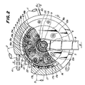
- Figs. 1 and 2 illustrate respective members associated with a speed change device, which are a head tube 1, a seat tube 2, chain stays 3, a bottom tube 4, a fixed bearing 5 also serving as a bearing cap and screwed in the bottom tube 4 to be integrally fixed to a bicycle frame, a crankshaft 6 rotatably extending through the fixed bearing 5, balls 7 for the bearing, and a crank arm 8 (only one shown) fitted on one end of the crankshaft 6 and clamped by a nut 9.
- a snap ring 10 serves to fix the bearing 10 to the bottom tube 4.
- a carrier 11 in the form of a disc is formed on its outer circumference with a projection 11a as a gear cover.
- a center portion of the carrier 11 is fitted on a boss of the crank arm 8 and is fixed to a flange portion of the crank arm 8 by means of bolts 12a (Fig. 2).
- a plurality (four in this embodiment) of shafts 13 are provided equally angularly spaced in a circle in the carrier 11 and in parallel with the crankshaft 6.
- the carrier is formed at four locations on an inner surface with protrusions 11b (Fig. 2).
- a ring plate 14 abuts against the protrusions 11b and is fixed thereto by means of bolts 12b (Fig. 3).
- the shafts 13 extend between the carrier 11 and the ring plate 14.
- a plurality (four in this embodiment) of planet gears 15 are rotatably fitted on the shafts 13.
- Each of the planet gears 15 consists of a plurality (three in this embodiment) of planet gear elements 15a, 15b and 15c having gear teeth different in number and integrally formed in a unitary body.
- a driven rotary body 16 is formed with an internal gear 16a adapted to be in mesh with planet gear elements 15b and is formed with roller receiving stepped portions 16b and 16c on both sides of the internal gear 16a.
- the driven rotary body 16 is further formed on its outer circumference with a sprocket 16d and a stepped cylindrical portion. In this manner the driven rotary body 16 is formed as a unitary body.
- the sprocket 16d is formed separately from the internal gear and the like and is integrally jointed to these members as shown in Fig. 1, in order to facilitate manufacturing of the driven rotary body 16.
- one-way clutches 17 are interposed between inner stepped portions provided on inner surfaces of outer periphery of the carrier 11 and the stepped cylindrical portion of the driven rotary body 16 to allow the rotary body to rotate only in one direction relative to the carrier 11.
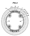
- the one-way clutch 17 consists of ratchet teeth 17a formed in the stepped cylindrical portion of the driven rotary body 16, a pawl 17b pivotally connected to the carrier 11 in extendable and retractable manner, and a spring 17c for urging the pawl 17b into engagement with the ratchet tooth 17a as shown in Figs. 2 and 4.
- the one-way clutch 17 may of course be formed in other types of one-way clutch.
- a plurality (four in this embodiment) of shafts 13a extend between the carrier 11 and the ring plate 14 and are arranged equally angularly spaced in a circle and in parallel with the crankshaft 6.
- shafts 13a On the shafts 13a are rotatably provided smaller diameter rollers 18a and larger diameter rollers 18b which are adapted to engage the roller receiving steps 16b and 16c of the driven rotary body 16, thereby supporting the driven rotary body.
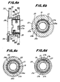
- a pawl sleeve 19 in the form of a hollow cylinder is fitted through involute serrations (Fig. 5) on the fixed bearing 5 enclosing the crankshaft 6.
- a speed change cylinder 21 on which is further fitted sun gears 22, 23 and 24 in mesh with the planet gear elements 15a, 15b and 15c of the planet gear 15.
- One-way clutches 25, 26 and 27 are provided between inner circumferences of these sun gears 22, 23 and 24 and an outer circumference of the pawl sleeve 19 and so constructed that one of the one-way clutches 25, 26 and 27 is selectively connected.
- the one-way clutches 25, 26 and 27 include pairs of pawls 25a, 26a and 27a.
- the respective pairs of pawls are diametrically opposed and pivotally connected in recesses formed in an outer circumference of the pawls sleeve 19 in an extendable and retractable manner.
- Fig. 6b illustrates the one-way clutch 25 associated with the sun gear 22.
- Fig. 6c illustrates the one-way clutch 26 associated with the sun gear 23.
- Fig. 6d illustrates the one-way clutch 27 associated with the sun gear 24.
- Annular springs 25b, 26b and 27b cause the pawls to extend outwardly.
- the sun gears are formed in their inner circumferences with ratchet teeth 25c, 26c and 27c.
- the pawls 25a, 26a and 27a are angularly shifted with 60° and pivotally connected to the outer circumference of the pawl sleeve 19.
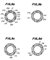
- the speed change cylinder 21 is formed with openings 21a, 21b and 21c corresponding to the pawls 25a, 25b and 25c, respectively. As shown in Fig. 7a, these openings 21a, 21b and 21c are so arranged in the speed change cylinder 21 that reference edges of the openings (preceding edges a, b and c in a clockwise direction) are angularly shifted by 60°, and lengths of the openings 21a, 21b and 21c are in a relation 21a ⁇ 21b ⁇ 21c.
- the openings 21a, 21b and 21c angularly extend in the speed change cylinder 21 over 28°, 41° and 51°, respectively.
- the speed change cylinder 21 is provided with a flange 21d on one side or the side of the crank arm 8 and is formed on the opposite side with an annular groove 21e and notches 21f at two diametrically opposed locations of edges on the side of the annular groove 21e.
- Fig. 8 illustrates in detail a shift arm 28 integrally jointed to the speed change cylinder 21 to effect speed change operation.
- the shift arm 28 comprises a ring portion 28a adapted to be fitted on the speed change cylinder 21, tongues 28b extending from an inside of the ring portion 28a and adapted to be fitted on the notches 21f of the speed change cylinder 21, respectively, an arm 28c laterally extending from an outer side edge of the ring portion 28a, a wire guide 28d extending in the form of a flange continuous with the arm 28c, and a spring anchoring aperture 28e and a wire anchoring aperture 28f formed in the arm 28c.
- the shift arm 28 is fitted on the speed change cylinder 21 so that the tongues 28b are fitted on the notches 21f and a snap ring is fitted in the annular groove 21a to joint the speed change cylinder 21 to the shift arm 28 so as to form a unitary body as shown in Figs. 1, 3 and 6a.
- a speed change operating wire 30 is fixed to the shift arm 28 by means of the aperture 28f, an anchoring metal 31 and a set screw 32 as shown in Fig. 3.
- a return spring 34 extends between the aperture 28e and a bracket 33 provided on the chain stay 3.
- reference numeral 35 denotes washers provided on side surfaces of the respective rotating members.
- a collar 36 is interposed between the carrier 11 and the sun gear 22.
- dust protective seals are used which are made of elastic materials such as soft polyvinyl chloride in order to close clearances between the rotating members.
- An annular seal 37 is fitted on an outer circumference of the driven rotary body 16 and an edge 37a of the annular seal 37 is fitted in an annular groove 11c formed in an inner surface of the carrier 11.
- An annular seal 38 closes the clearances between an outer periphery of the ring plate 14 and the driven rotary body 16.
- An annular seal 39 closes the clearance between an inner periphery of the ring plate 14 and an outer periphery of the ring portion 28a of the shift arm 28.
- a seal 40 in the form of a ring plate closes the clearance between an outer circumference of the fixed bearing 5 and an inner periphery of the ring portion 28a of the shift arm 28.
- Reference numeral 41 denotes a chain engaging the sprocket 16c.
- the driven rotary body 16 and the sprocket 16d are rotated together with the crank arm 8 in the direction shown by the arrow C so that the chain 41 moves in a direction shown by an arrow D in Fig. 2 to drive a rear wheel (not shown), thereby driving the bicycle.
- the speed change ratio between the crankshaft 6 and the sprocket 16d is 1:1.
- the sun gears 22, 23 and 24 are idlingly fitted on the speed change cylinder 21.
- the sun gears are inscribed and engaged with the four planet gears in this embodiment, respectively, it is not needed to journal the sun gears by a center shaft.
- the pawls 27a in the openings 21c are engaged with the ratchet teeth 27c, the pawls 27a extend in directions which permit the ratchet teeth 27c of the sun gear 24 to rotate, so that the engagement of the pawls 27a with the ratchet teeth 27c does not interfere with other members.
- the openings 21a are moved into the positions shown in Fig. 9d or Fig. 9b, so that the third pawls 25a extend through the openings 21a so as to engage the ratchet teeth 25c of the sun gear 22 as shown in Fig. 6b.
- the operating wire 30 is pulled in a direction shown by the arrow A in Fig. 2 to bring the speed change cylinder 21 from the condition shown in Fig. 9d progressively into the conditions shown in Figs. 9c, 9b and 9a in a manner reverse to that of speed-up, thereby effecting the slowing down in the order of 4, 3, 2 and 1.
- one set among three sets of the pawls 25a, 26a and 27a extend through the openings one set by one set to engage the corresponding ratchet teeth in speeding-up and one set of the pawls retracted inwardly of the openings one set by one set in slowing down.
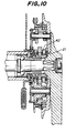
- a collar 42 is fitted on the speed change cylinder without providing the sun gear 22 and the one-way clutch 25 to provide a three-stage speed change device of 1:1, 1:1.4 and 1:1.6 devoid of a fourth stage speed change performance as shown in Fig. 10.
- the driven rotary body 16 only one internal gear 16a, so that the driven rotary body 16 becomes easy to manufacture and is securely supported by the rollers 18a and 18b and the like.
- the planet gear 15 consists of a plurality of planet gear elements 15a, 15b and 15c integrally formed in a unitary body and is journaled by the shaft 13, and a plurality of sun gears 22, 23 and 24 in mesh these planet gears 15a, 15b and 15c are arranged on the crankshaft 6.
- the shaft 13 of the planet gear elements 15a, 15b and 15c is a common one therefor and the many (four in the embodiment) shafts 13 are arranged in a circle, so that loads which the respective planet gears should support are less and the device can be made thin as a whole.
- the driving force is transmitted from the carrier to the driven rotary body 16 through the one-way clutch 17 for the first step, through the sun gear 24, the planet gear elements 15c and the internal gear 16a for the second step, through the sun gear 23, the planet gear elements 15b and the internal gear 16a for the third step, and through the sun gear 22, the planet gear elements 15a and the internal gear 16a for the fourth step.
- any driving force is transmitted in linear transmission passages intersecting substantially at right angles to the crankshaft 6 for all the speed change steps.
- the shafts for the respective gears are supported at both ends, so that the transmission efficiency of the gears is high and superior in constructional strength. Therefore, the described speed change device is easy to manufacture and durable in use.
- At least three shafts 13a are provided in a circle on the carrier 11 and rollers 18a and 18b are rotatably arranged on the shafts 13 for supporting the stepped portions 16b and 16c formed inner circumference of the driven rotary body 16, thereby securely supporting the driven rotary body 16 and making smooth the engagement and rotation of the internal gear 16a and planet gears 15.
- the fixed bearing 5 enclosing the crankshaft 6 is formed in its outer circumference with serrations 20 and the pawl sleeve 19 provided in an outer circumference with a plurality of pawls is formed in the inner circumference with serration 20 and is detachably fitted on the fixed bearing 5. Therefore, the most of the parts already assembled may be finally fitted into a frame assembly of a bicycle, so that the assembling and disassembling of the device are very easy for the purpose of manufacturing or maintenance of the device.
- the pawl sleeve 19 is fitted on the fixed bearing 5 enclosing the crankshaft 6 through the serrations 20 and one-way clutches 25, 26 and 27 are provided between the pawl sleeve 19 and the sun gears 22, 23 and 24. Further, the speed change cylinder 21 is provided for controlling these one-way clutches 25, 26 and 27.
- the shift arm 28 is engaged with one end of the speed change cylinder 21 and fixed thereto by the snap ring. Therefore, after the speed change cylinder 21, the pawl sleeve 19, the plurality of sun gears 22, 23 and 24 and the plurality of one-way clutches 25, 26 and 28 have been assembled, this assembly is fitted and connected with the shift arm 28 by means of the snap ring 29 in a simple manner. Therefore, the device is easy to assemble for manufacturing and maintenance of the device and therefore the device becomes superior in quality.
- the pawl sleeve 19 is fitted on the fixed bearing 5 enclosing the crankshaft 6, and a speed change cylinder 21 is rotatably fitted between the pawl sleeve 19 and the sun gears 22, 23 and 24.
- the pawl sleeve 19 is provided on its outer circumference with a plurality of pawls 25a, 26a and 27a extensible and retractable in opposition to the sun gears and the speed change cylinder 21 is formed with openings 21a, 21b and 21c corresponding to the pawls to form the one-way clutches 25, 26 and 27 corresponding to the sun gears 22, 23 and 24, thereby selectively connecting one of the one-way clutches 25, 26 and 27 by rotating operation of the speed change cylinder 21.
- the control of the respective one-way clutches 25, 26 and 27 can be smoothly effected by means of the speed change cylinder 21 which is thin and of light weight but has a high strength.
- the openings 21a, 21b and 21c through which the pawls 25a, 26a and 27a are extended or retracted are independently distributed in the speed change cylinder, edges of the openings have enough strength to resist forces of the pawls tending to extend out of the speed change cylinder.
- the one-way clutch includes a plurality of pawls to improve the balancing of forces when engaged and therefore the device becomes durable in use.
- the carrier 11 is provided on its outer circumference with a projection 11a as a gear cover. Moreover, there are provided dust protection seals 37, 38, 39 and 40 between the carrier 11 and the driven rotary body 16, between the driven rotary body 16 and the outer circumference of the ring plate 14 integrally connected to the carrier 11, between the inner periphery of the ring plate 14 and the outer periphery of the ring portion 28a of the shift arm 28 for controlling the one way clutches for the sun gears and between the inner periphery of the ring portion 28a of the shift arm 28 and the outer circumference of the fixed bearing 5. Therefore, clothes of a cyclist are prevented from being carried along by a projection 11a of the carrier into spaces between the sprocket 16d and the chain 41. Moreover, the respective dust protecting seals 37, 38, 39 and 40 surely prevent the dust, muddy water and the like from entering the device. Therefore, according to some embodiments of the invention it is possible to improve the safety in riding on a bicycle and simultaneously the durability of the bicycle.
Landscapes
- Engineering & Computer Science (AREA)
- Chemical & Material Sciences (AREA)
- Combustion & Propulsion (AREA)
- Transportation (AREA)
- Mechanical Engineering (AREA)
- Structure Of Transmissions (AREA)
- Transmission Devices (AREA)
Claims (7)
- Dispositif de changement de vitesse pour bicyclette comportant un support (11) relié à un bras de manivelle (8), une pluralité d'engrenages planétaires (15) supportés en rotation par une pluralité d'arbres (13) disposés suivant un cercle sur ledit support, chacun desdits engrenages planétaires comprenant une pluralité d'éléments d'engrenages planétaires (15a, 15b, 15c) différant par le nombre de dents, caractérisé en ce que le dispositif comporte en outre un engrenage interne (16a) en prise avec l'un desdits éléments d'engrenages planétaires des engrenages planétaires et ayant une roue dentée (16d) formée sur sa circonférence extérieure pour constituer un corps rotatif mené (16), un premier embrayage unidirectionnel (17) pour connecter ledit corps rotatif mené audit support, une pluralité d'engrenages solaires (22, 23, 24) prévus sur un vilebrequin (6) et respectivement en prise avec lesdits éléments d'engrenages planétaires desdits engrenages planétaires, et une pluralité de deuxièmes embrayages unidirectionnels (25, 26, 27) prévus entre les circonférences intérieures de chacun desdits engrenages solaires et un palier fixe (5) enfermant ledit vilebrequin, lesdits deuxièmes embrayages unidirectionnels étant sélectivement connectables.
- Dispositif de changement de vitesse selon la revendication 1, dans lequel ledit dispositif comporte en outre au moins trois arbres (13a) montés suivant un cercle sur ledit support et des galets (18a, 18b) montés rotatifs sur lesdits arbres pour supporter une circonférence intérieure dudit corps rotatif mené.
- Dispositif de changement de vitesse selon les revendications 1 ou 2, dans lequel ledit palier fixe (5) comporte formées sur sa circonférence extérieure des cannelures, et un manchon à rochets (19) sous forme d'un cylindre creux a des cannelures sur sa surface intérieure et est monté détachable sur ledit palier fixe, et dans lequel lesdits deuxièmes embrayages unidirectionnels (25, 26, 27) sont montés entre lesdits engrenages solaires (22, 23, 24) et le manchon à rochets.
- Dispositif de changement de vitesse selon la revendication 3, dans lequel des rochets (25a, 26a, 27a) desdits deuxièmes embrayages unidirectionnels sont montés sur une circonférence extérieure dudit manchon à rochets (19) et des dents d'encliquetage (25c, 26c, 27c) desdits embrayages unidirectionnels sont montées sur la circonférence intérieure desdits engrenages solaires.
- Dispositif de changement de vitesse selon les revendications 3 ou 4, dans lequel ledit dispositif comporte en outre un cylindre de changement de vitesse (21) peur commander lesdits embrayages unidirectionnels montés entre lesdits engrenages solaires et le manchon à rochets, ledit cylindre de changement de vitesse étant connecté à un bras de commutation (28) pour le changement des vitesses.
- Dispositif de changement de vitesse selon l'une quelconque des revendications précédentes, dans lequel ledit dispositif comporte en outre un manchon à rochets (19) sous la forme d'un cylindre creux monté sur ledit palier fixe (5) et un cylindre de changement de vitesse (21) monté rotatif entre ledit manchon à rochets (17) et les engrenages solaires (22, 23, 24), ledit manchon à rochets comportant sur sa circonférence extérieure une pluralité de rochets (25a, 26a, 27a) extensibles et rétractables en opposition avec les engrenages solaires, des ouvertures (21a, 21b, 21c) étant ménagées dans ledit cylindre de changement de vitesse correspondant auxdits rochets pour constituer lesdits embrayages unidirectionnels correspondant auxdits engrenages solaires, permettant ainsi de connecter de façon sélective l'un desdits embrayages unidirectionnels par la rotation dudit cylindre de changement de vitesse.
- Dispositif de changement de vitesse selon l'une quelconque des revendications précédentes, dans lequel le dispositif comporte en outre des joints d'étanchéité à la poussière (37, 38, 39, 40) entre ledit support (11) et ledit corps rotatif mené (16), entre une circonférence extérieure d'une plaque annulaire (14) située sur un côté opposé dudit support (11) et ledit corps rotatif mené (16), entre une périphérie intérieure de ladite plaque annulaire (14) et une périphérie extérieure d'une partie annulaire (28a) d'un arbre de changement de vitesse (28) pour commander lesdits embrayages unidirectionnels pour lesdits engrenages solaires, et entre une périphérie intérieure de ladite partie annulaire (28a) dudit arbre de changement de vitesse (28) et une circonférence extérieure dudit palier fixe (5).
Applications Claiming Priority (12)
| Application Number | Priority Date | Filing Date | Title |
|---|---|---|---|
| JP21822786A JPS6374788A (ja) | 1986-09-18 | 1986-09-18 | 自転車用変速装置 |
| JP21823086A JPS6374791A (ja) | 1986-09-18 | 1986-09-18 | 自転車用変速装置 |
| JP21822686A JPS6374787A (ja) | 1986-09-18 | 1986-09-18 | 自転車用変速装置 |
| JP218227/86 | 1986-09-18 | ||
| JP218229/86 | 1986-09-18 | ||
| JP218226/86 | 1986-09-18 | ||
| JP218230/86 | 1986-09-18 | ||
| JP218225/86 | 1986-09-18 | ||
| JP21822986A JPS6374790A (ja) | 1986-09-18 | 1986-09-18 | 自転車用変速装置 |
| JP21822886A JPS6374789A (ja) | 1986-09-18 | 1986-09-18 | 自転車用変速装置 |
| JP21822586A JPS6374786A (ja) | 1986-09-18 | 1986-09-18 | 自転車用変速装置 |
| JP218228/86 | 1986-09-18 |
Publications (3)
| Publication Number | Publication Date |
|---|---|
| EP0262841A2 EP0262841A2 (fr) | 1988-04-06 |
| EP0262841A3 EP0262841A3 (en) | 1989-01-18 |
| EP0262841B1 true EP0262841B1 (fr) | 1991-09-04 |
Family
ID=27553943
Family Applications (1)
| Application Number | Title | Priority Date | Filing Date |
|---|---|---|---|
| EP87308253A Expired - Lifetime EP0262841B1 (fr) | 1986-09-18 | 1987-09-17 | Dispositif de changement de vitesse pour bicyclette |
Country Status (3)
| Country | Link |
|---|---|
| US (1) | US4838122A (fr) |
| EP (1) | EP0262841B1 (fr) |
| DE (1) | DE3772693D1 (fr) |
Cited By (2)
| Publication number | Priority date | Publication date | Assignee | Title |
|---|---|---|---|---|
| US10094452B1 (en) | 2013-03-05 | 2018-10-09 | Mark B. Sullivan | Continuously variable transmission for a bicycle |
| CN111619723A (zh) * | 2020-07-08 | 2020-09-04 | 黎永杰 | 滑轮组与杠杆组合驱动装置和自行车 |
Families Citing this family (55)
| Publication number | Priority date | Publication date | Assignee | Title |
|---|---|---|---|---|
| US4916974A (en) * | 1987-02-21 | 1990-04-17 | Bridgestone Cycle Co., Ltd. | Stepless speed change device |
| US5125489A (en) * | 1990-10-09 | 1992-06-30 | Cha Pyong I | High-torque dual-purpose hub assembly for the rear wheel of a multispeed bicycle |
| US5855530A (en) * | 1997-07-30 | 1999-01-05 | Industrial Technology Research Institute | Speed-changing transmission hub for a bicycle |
| US6551210B2 (en) | 2000-10-24 | 2003-04-22 | Motion Technologies, Llc. | Continuously variable transmission |
| KR100436697B1 (ko) * | 1999-12-15 | 2004-06-22 | 오종수 | 자전거의 속도변환장치 |
| EP2261537A3 (fr) | 2001-04-26 | 2012-06-13 | Fallbrook Technologies Inc. | Transmission variable continue |
| US7011600B2 (en) * | 2003-02-28 | 2006-03-14 | Fallbrook Technologies Inc. | Continuously variable transmission |
| US7166052B2 (en) * | 2003-08-11 | 2007-01-23 | Fallbrook Technologies Inc. | Continuously variable planetary gear set |
| MX364884B (es) * | 2004-10-05 | 2019-05-10 | Fallbrook Intellectual Property Company Llc Star | Transmisión continuamente variable. |
| ES2439236T3 (es) * | 2005-08-24 | 2014-01-22 | Fallbrook Intellectual Property Company Llc | Turbina eólica |
| KR20130018976A (ko) * | 2005-10-28 | 2013-02-25 | 폴브룩 테크놀로지즈 인크 | 전기 기계 동력 전달 방법 |
| US20070155567A1 (en) * | 2005-11-22 | 2007-07-05 | Fallbrook Technologies Inc. | Continuously variable transmission |
| CN102226464B (zh) * | 2005-12-09 | 2013-04-17 | 福博科技术公司 | 一种用于变速器的轴向力产生机构 |
| EP1811202A1 (fr) | 2005-12-30 | 2007-07-25 | Fallbrook Technologies, Inc. | Transmission à variation continue |
| US7882762B2 (en) | 2006-01-30 | 2011-02-08 | Fallbrook Technologies Inc. | System for manipulating a continuously variable transmission |
| WO2007106874A2 (fr) | 2006-03-14 | 2007-09-20 | Autocraft Industries, Inc. | Fauteuil roulant ameliore |
| CN102269056B (zh) | 2006-06-26 | 2013-10-23 | 福博科技术公司 | 无级变速器 |
| EP2089642B1 (fr) | 2006-11-08 | 2013-04-10 | Fallbrook Intellectual Property Company LLC | Générateur de force de fixation par serrage |
| EP2125469A2 (fr) | 2007-02-01 | 2009-12-02 | Fallbrook Technologies Inc. | Système et procédés pour la commande d'une transmission et/ou d'un premier moteur d'entraînement |
| CN101657653B (zh) | 2007-02-12 | 2014-07-16 | 福博科知识产权有限责任公司 | 一种传动装置 |
| WO2008101070A2 (fr) | 2007-02-16 | 2008-08-21 | Fallbrook Technologies Inc. | Transmissions infiniment variables, transmissions variables en continu, procédés, ensembles, sous-ensembles, et composants de celles-ci |
| EP2142826B1 (fr) | 2007-04-24 | 2015-10-28 | Fallbrook Intellectual Property Company LLC | Entraînements de traction électrique |
| US8641577B2 (en) | 2007-06-11 | 2014-02-04 | Fallbrook Intellectual Property Company Llc | Continuously variable transmission |
| KR20100046166A (ko) | 2007-07-05 | 2010-05-06 | 폴브룩 테크놀로지즈 인크 | 연속 가변 변속기 |
| CN101397048A (zh) * | 2007-09-29 | 2009-04-01 | 程辉 | 一种自行车全自动变速器 |
| CN103939602B (zh) | 2007-11-16 | 2016-12-07 | 福博科知识产权有限责任公司 | 用于变速传动装置的控制器 |
| EP2234869B1 (fr) | 2007-12-21 | 2012-07-04 | Fallbrook Technologies Inc. | Transmissions automatiques et procedes correspondants |
| WO2009111328A1 (fr) | 2008-02-29 | 2009-09-11 | Fallbrook Technologies Inc. | Transmissions à variation continue et/ou infinie et procédés associés |
| US8317651B2 (en) | 2008-05-07 | 2012-11-27 | Fallbrook Intellectual Property Company Llc | Assemblies and methods for clamping force generation |
| JP5457438B2 (ja) | 2008-06-06 | 2014-04-02 | フォールブルック インテレクチュアル プロパティー カンパニー エルエルシー | 無限可変変速機、及び無限可変変速機用の制御システム |
| CN107246463A (zh) | 2008-06-23 | 2017-10-13 | 福博科知识产权有限责任公司 | 无级变速器 |
| WO2010017242A1 (fr) | 2008-08-05 | 2010-02-11 | Fallbrook Technologies Inc. | Procédés de commande d'une transmission et/ou d'une machine motrice |
| US8469856B2 (en) | 2008-08-26 | 2013-06-25 | Fallbrook Intellectual Property Company Llc | Continuously variable transmission |
| US8167759B2 (en) | 2008-10-14 | 2012-05-01 | Fallbrook Technologies Inc. | Continuously variable transmission |
| KR101718754B1 (ko) | 2009-04-16 | 2017-03-22 | 폴브룩 인텔렉츄얼 프로퍼티 컴퍼니 엘엘씨 | 무단 변속기를 위한 고정자 조립체 및 시프팅 장치 |
| US20100264619A1 (en) * | 2009-04-21 | 2010-10-21 | Ernesto Haynes | Bicycle pedaling system |
| US8342553B2 (en) * | 2009-05-27 | 2013-01-01 | Patterson Bicycle Transmission Llc | Mounting method for bottom bracket planetary |
| GB2474830A (en) * | 2009-08-14 | 2011-05-04 | Edward Bolam | Gearing arrangement with planet gears having different relative sizes |
| US8512195B2 (en) | 2010-03-03 | 2013-08-20 | Fallbrook Intellectual Property Company Llc | Infinitely variable transmissions, continuously variable transmissions, methods, assemblies, subassemblies, and components therefor |
| US8888643B2 (en) | 2010-11-10 | 2014-11-18 | Fallbrook Intellectual Property Company Llc | Continuously variable transmission |
| FR2969982A1 (fr) * | 2011-01-05 | 2012-07-06 | Lyon Ecole Centrale | Boite de vitesses, en particulier pour un velo tout-terrain |
| WO2012138610A1 (fr) | 2011-04-04 | 2012-10-11 | Fallbrook Intellectual Property Company Llc | Groupe auxiliaire de puissance doté d'une transmission à variation continue |
| JP6175450B2 (ja) | 2012-01-23 | 2017-08-02 | フォールブルック インテレクチュアル プロパティー カンパニー エルエルシー | 無限可変変速機、連続可変変速機、方法、組立体、部分組立体およびその構成要素 |
| ITMI20120088U1 (it) * | 2012-03-08 | 2013-09-09 | Campagnolo Srl | Assieme di pedivella destra per bicicletta |
| PL221732B1 (pl) * | 2012-06-20 | 2016-05-31 | Bogusława Janowska | Przekładnia planetarna |
| CN109018173B (zh) | 2013-04-19 | 2021-05-28 | 福博科知识产权有限责任公司 | 无级变速器 |
| US10047861B2 (en) | 2016-01-15 | 2018-08-14 | Fallbrook Intellectual Property Company Llc | Systems and methods for controlling rollback in continuously variable transmissions |
| DK3414152T3 (da) * | 2016-02-12 | 2020-07-20 | Moeve Bikes Gmbh | Cykelgear med ikke-rundt kædehjul |
| US10389208B2 (en) * | 2016-03-09 | 2019-08-20 | Johnson Controls Technology Company | HVAC actuator with one-way clutch motor |
| US10458526B2 (en) | 2016-03-18 | 2019-10-29 | Fallbrook Intellectual Property Company Llc | Continuously variable transmissions, systems and methods |
| US10023266B2 (en) | 2016-05-11 | 2018-07-17 | Fallbrook Intellectual Property Company Llc | Systems and methods for automatic configuration and automatic calibration of continuously variable transmissions and bicycles having continuously variable transmissions |
| PL420541A1 (pl) * | 2017-02-15 | 2018-08-27 | Efneo Spółka Z Ograniczoną Odpowiedzialnością | Podpora sprzęgła przekładni |
| CN107975570B (zh) * | 2017-11-28 | 2020-05-12 | 西南大学 | 用于水下潜行器的电机两挡自动变速器及换挡方法 |
| US11215268B2 (en) | 2018-11-06 | 2022-01-04 | Fallbrook Intellectual Property Company Llc | Continuously variable transmissions, synchronous shifting, twin countershafts and methods for control of same |
| US11174922B2 (en) | 2019-02-26 | 2021-11-16 | Fallbrook Intellectual Property Company Llc | Reversible variable drives and systems and methods for control in forward and reverse directions |
Family Cites Families (20)
| Publication number | Priority date | Publication date | Assignee | Title |
|---|---|---|---|---|
| LU28844A1 (fr) * | ||||
| GB190524929A (en) * | 1905-10-02 | 1906-04-12 | Alfred Jukes Allen | A Three-speed Mechanism |
| FR546224A (fr) * | 1922-01-21 | 1922-11-03 | Perfectionnements apportés aux dispositifs de transmission centrifuge | |
| US2201304A (en) * | 1938-10-01 | 1940-05-21 | Bendix Aviat Corp | Gear changing mechanism |
| CH234698A (de) * | 1944-01-25 | 1944-10-15 | Willem Mynssen Jacob | Dreiganggetriebe für Fahrräder. |
| CH254702A (it) * | 1946-10-29 | 1948-05-15 | Costa Gaetano | Cambio di velocità per biciclette racchiuso nel mozzo della ruota motrice. |
| DE848016C (de) * | 1946-11-30 | 1952-09-01 | Jean Raymond Barthelemy Monge | Tretkurbelantrieb fuer Fahrraeder, Motorfahrraeder u. dgl. |
| US2988186A (en) * | 1958-06-06 | 1961-06-13 | Fichtel & Sachs Ag | Device for disengaging ratchet gears |
| DE1505933B1 (de) * | 1961-05-05 | 1969-09-04 | Fichtel & Sachs Ag | Freilaufnabe fuer Fahrraeder,Motorraeder od.dgl. |
| US3135368A (en) * | 1961-11-25 | 1964-06-02 | Shimano Keizo | Bicycle hub having a built-in two-stage speed change mechanism |
| NL293107A (fr) * | 1962-05-25 | |||
| DE1276488B (de) * | 1966-02-02 | 1968-08-29 | Fichtel & Sachs Ag | Mehrganguebersetzungsnabe fuer Fahrraeder, Mopeds od. dgl. |
| US3727484A (en) * | 1971-05-03 | 1973-04-17 | Dana Corp | Speed changing transmission |
| US3766805A (en) * | 1972-01-24 | 1973-10-23 | Dana Corp | Speed changing transmissions |
| US4157667A (en) * | 1976-10-04 | 1979-06-12 | Giovanna Rinaldi | Variable ratio drive for gearing rotating parts to one another utilizable for cycles, motorcycles, motor vehicles and machines in general |
| US4098147A (en) * | 1976-11-01 | 1978-07-04 | Avco Corporation | Waddington drive having a cam actuated by an integral flyweight |
| US4305312A (en) * | 1977-06-27 | 1981-12-15 | Lapeyre Fernand S | Bicycle transmission |
| US4583427A (en) * | 1984-03-23 | 1986-04-22 | Tamille Pty. Limited | Gear box |
| US4706982A (en) * | 1986-04-21 | 1987-11-17 | Hartmann Dirck T | Dual range planetary transmission for pedal powered vehicles |
| US4721015A (en) * | 1986-09-08 | 1988-01-26 | Hartmann Dirck T | Three stage planetary driving wheel for pedal powered vehicles |
-
1987
- 1987-09-14 US US07/095,851 patent/US4838122A/en not_active Expired - Fee Related
- 1987-09-17 EP EP87308253A patent/EP0262841B1/fr not_active Expired - Lifetime
- 1987-09-17 DE DE8787308253T patent/DE3772693D1/de not_active Expired - Fee Related
Cited By (3)
| Publication number | Priority date | Publication date | Assignee | Title |
|---|---|---|---|---|
| US10094452B1 (en) | 2013-03-05 | 2018-10-09 | Mark B. Sullivan | Continuously variable transmission for a bicycle |
| CN111619723A (zh) * | 2020-07-08 | 2020-09-04 | 黎永杰 | 滑轮组与杠杆组合驱动装置和自行车 |
| CN111619723B (zh) * | 2020-07-08 | 2021-08-20 | 黎永杰 | 滑轮组与杠杆组合驱动装置和自行车 |
Also Published As
| Publication number | Publication date |
|---|---|
| EP0262841A2 (fr) | 1988-04-06 |
| EP0262841A3 (en) | 1989-01-18 |
| DE3772693D1 (de) | 1991-10-10 |
| US4838122A (en) | 1989-06-13 |
Similar Documents
| Publication | Publication Date | Title |
|---|---|---|
| EP0262841B1 (fr) | Dispositif de changement de vitesse pour bicyclette | |
| US7621842B2 (en) | Bicycle hub assembly | |
| US6478711B2 (en) | Apparatus for changing speed of bicycles | |
| JP4705131B2 (ja) | 自転車用内装変速ハブ | |
| US4721015A (en) | Three stage planetary driving wheel for pedal powered vehicles | |
| US7644944B2 (en) | Multiple gear transmission for a bicycle | |
| US6468178B1 (en) | Rear wheel hub with drive train gear assembly, spindle and cranks for use on a bicycle | |
| EP1980484A1 (fr) | Système d'assemblage pour transmission de bicyclette interne | |
| US5399128A (en) | Multi-speed drive hub with a separate mounting ring for the planetary gearset for bicycles | |
| EP1982913A1 (fr) | Transmission pour bicyclette | |
| US20110130242A1 (en) | Multi-Speed Internal Gear Hub for a Bicycle | |
| NO345740B1 (en) | Clutch and multispeed gear | |
| US5048358A (en) | Rotary phased radial thrust variable drive transmission | |
| CN2402101Y (zh) | 自由轮毂装置 | |
| US5556354A (en) | Shifting arrangement for a change gear drive in multispeed hubs for bicycles | |
| EP0191604B1 (fr) | Dispositif de changement de vitesse continu | |
| US9139254B2 (en) | Universal low-friction bicycle hub transmission | |
| TW202440355A (zh) | 手自一體內變速花鼓及自行車 | |
| GB2295427A (en) | Crank assembly for a bicycle in which ratio is changed by reversing rotation of pedals | |
| EP2075186B1 (fr) | Transmission à moyeu interne de bicyclette avec engrenage hélicoïdal | |
| CN219883617U (zh) | 一种手自一体内变速花鼓及自行车 | |
| US3433097A (en) | Epicyclic change speed gear hubs | |
| EP1686055B1 (fr) | Moyeu d'entraînement de bicyclette | |
| KR101889751B1 (ko) | 회전력을 증가시키기 위한 기어장치 | |
| WO2020111569A1 (fr) | Dispositif d'engrenage à vitesse variable de manivelle pour augmenter la puissance de rotation |
Legal Events
| Date | Code | Title | Description |
|---|---|---|---|
| PUAI | Public reference made under article 153(3) epc to a published international application that has entered the european phase |
Free format text: ORIGINAL CODE: 0009012 |
|
| AK | Designated contracting states |
Kind code of ref document: A2 Designated state(s): DE FR GB IT NL |
|
| PUAL | Search report despatched |
Free format text: ORIGINAL CODE: 0009013 |
|
| AK | Designated contracting states |
Kind code of ref document: A3 Designated state(s): DE FR GB IT NL |
|
| 17P | Request for examination filed |
Effective date: 19890407 |
|
| 17Q | First examination report despatched |
Effective date: 19900625 |
|
| GRAA | (expected) grant |
Free format text: ORIGINAL CODE: 0009210 |
|
| AK | Designated contracting states |
Kind code of ref document: B1 Designated state(s): DE FR GB IT NL |
|
| ITF | It: translation for a ep patent filed | ||
| REF | Corresponds to: |
Ref document number: 3772693 Country of ref document: DE Date of ref document: 19911010 |
|
| ET | Fr: translation filed | ||
| PLBE | No opposition filed within time limit |
Free format text: ORIGINAL CODE: 0009261 |
|
| STAA | Information on the status of an ep patent application or granted ep patent |
Free format text: STATUS: NO OPPOSITION FILED WITHIN TIME LIMIT |
|
| 26N | No opposition filed | ||
| PGFP | Annual fee paid to national office [announced via postgrant information from national office to epo] |
Ref country code: GB Payment date: 19930907 Year of fee payment: 7 |
|
| PGFP | Annual fee paid to national office [announced via postgrant information from national office to epo] |
Ref country code: NL Payment date: 19930930 Year of fee payment: 7 |
|
| PG25 | Lapsed in a contracting state [announced via postgrant information from national office to epo] |
Ref country code: GB Effective date: 19940917 |
|
| PG25 | Lapsed in a contracting state [announced via postgrant information from national office to epo] |
Ref country code: NL Effective date: 19950401 |
|
| NLV4 | Nl: lapsed or anulled due to non-payment of the annual fee | ||
| GBPC | Gb: european patent ceased through non-payment of renewal fee |
Effective date: 19940917 |
|
| PGFP | Annual fee paid to national office [announced via postgrant information from national office to epo] |
Ref country code: FR Payment date: 19950911 Year of fee payment: 9 |
|
| PG25 | Lapsed in a contracting state [announced via postgrant information from national office to epo] |
Ref country code: FR Effective date: 19960930 |
|
| REG | Reference to a national code |
Ref country code: FR Ref legal event code: ST |
|
| REG | Reference to a national code |
Ref country code: FR Ref legal event code: ST |
|
| PGFP | Annual fee paid to national office [announced via postgrant information from national office to epo] |
Ref country code: DE Payment date: 19980925 Year of fee payment: 12 |
|
| PG25 | Lapsed in a contracting state [announced via postgrant information from national office to epo] |
Ref country code: DE Free format text: LAPSE BECAUSE OF NON-PAYMENT OF DUE FEES Effective date: 20000701 |
|
| PG25 | Lapsed in a contracting state [announced via postgrant information from national office to epo] |
Ref country code: IT Free format text: LAPSE BECAUSE OF NON-PAYMENT OF DUE FEES;WARNING: LAPSES OF ITALIAN PATENTS WITH EFFECTIVE DATE BEFORE 2007 MAY HAVE OCCURRED AT ANY TIME BEFORE 2007. THE CORRECT EFFECTIVE DATE MAY BE DIFFERENT FROM THE ONE RECORDED. Effective date: 20050917 |