EP0262865B1 - Einrichtung zur Entfernung von Glasbläschen enthaltenden Zyanobakterien aus Wasser - Google Patents
Einrichtung zur Entfernung von Glasbläschen enthaltenden Zyanobakterien aus Wasser Download PDFInfo
- Publication number
- EP0262865B1 EP0262865B1 EP87308442A EP87308442A EP0262865B1 EP 0262865 B1 EP0262865 B1 EP 0262865B1 EP 87308442 A EP87308442 A EP 87308442A EP 87308442 A EP87308442 A EP 87308442A EP 0262865 B1 EP0262865 B1 EP 0262865B1
- Authority
- EP
- European Patent Office
- Prior art keywords
- water
- bore
- hole
- cyanobacteria
- pipe
- Prior art date
- Legal status (The legal status is an assumption and is not a legal conclusion. Google has not performed a legal analysis and makes no representation as to the accuracy of the status listed.)
- Expired - Lifetime
Links
- XLYOFNOQVPJJNP-UHFFFAOYSA-N water Substances O XLYOFNOQVPJJNP-UHFFFAOYSA-N 0.000 title claims abstract description 81
- 241000192700 Cyanobacteria Species 0.000 title claims abstract description 55
- 229910000831 Steel Inorganic materials 0.000 claims abstract description 9
- 239000010959 steel Substances 0.000 claims abstract description 9
- 230000002706 hydrostatic effect Effects 0.000 claims description 15
- 238000000034 method Methods 0.000 abstract description 15
- 239000013049 sediment Substances 0.000 abstract description 4
- 239000007789 gas Substances 0.000 description 39
- 238000010276 construction Methods 0.000 description 5
- 239000002002 slurry Substances 0.000 description 5
- 230000015572 biosynthetic process Effects 0.000 description 3
- 239000002699 waste material Substances 0.000 description 3
- 241001464430 Cyanobacterium Species 0.000 description 2
- 241000192534 Dolichospermum flos-aquae Species 0.000 description 2
- QVGXLLKOCUKJST-UHFFFAOYSA-N atomic oxygen Chemical compound [O] QVGXLLKOCUKJST-UHFFFAOYSA-N 0.000 description 2
- 239000000463 material Substances 0.000 description 2
- 239000001301 oxygen Substances 0.000 description 2
- 229910052760 oxygen Inorganic materials 0.000 description 2
- 238000004062 sedimentation Methods 0.000 description 2
- 239000010802 sludge Substances 0.000 description 2
- 239000007787 solid Substances 0.000 description 2
- 241000894007 species Species 0.000 description 2
- 241000239290 Araneae Species 0.000 description 1
- 230000000721 bacterilogical effect Effects 0.000 description 1
- 230000002596 correlated effect Effects 0.000 description 1
- 210000002310 elbow joint Anatomy 0.000 description 1
- 238000002474 experimental method Methods 0.000 description 1
- 238000004880 explosion Methods 0.000 description 1
- 239000013505 freshwater Substances 0.000 description 1
- 230000005484 gravity Effects 0.000 description 1
- 238000002347 injection Methods 0.000 description 1
- 239000007924 injection Substances 0.000 description 1
- 239000007788 liquid Substances 0.000 description 1
- 230000035515 penetration Effects 0.000 description 1
- 238000005086 pumping Methods 0.000 description 1
- 238000000746 purification Methods 0.000 description 1
- 238000012552 review Methods 0.000 description 1
- 239000010865 sewage Substances 0.000 description 1
- 239000002910 solid waste Substances 0.000 description 1
- 238000002604 ultrasonography Methods 0.000 description 1
- 239000002351 wastewater Substances 0.000 description 1
Images


Classifications
-
- C—CHEMISTRY; METALLURGY
- C02—TREATMENT OF WATER, WASTE WATER, SEWAGE, OR SLUDGE
- C02F—TREATMENT OF WATER, WASTE WATER, SEWAGE, OR SLUDGE
- C02F3/00—Biological treatment of water, waste water, or sewage
- C02F3/32—Biological treatment of water, waste water, or sewage characterised by the animals or plants used, e.g. algae
-
- C—CHEMISTRY; METALLURGY
- C02—TREATMENT OF WATER, WASTE WATER, SEWAGE, OR SLUDGE
- C02F—TREATMENT OF WATER, WASTE WATER, SEWAGE, OR SLUDGE
- C02F1/00—Treatment of water, waste water, or sewage
Definitions
- the present invention relates to an apparatus for the treatment of water to remove gas vacuolate cyanobacteria.
- the water to be treated before being supplied to the customer is first allowed to stand in settlement tanks where the sediment and foreign bodies in the water taken from the reservoir or lake is allowed to settle to form a sludge at the bottom.
- cyanobacteria otherwise known as blue-green algae can form in a lake or reservoir. These cyanobacteria cannot be removed in settlement tanks because they float upwards and on the surface of the water.
- the gas vesicles of cyanobacteria are hollow, cylindrical structures with cone shaped ends.
- a gas vesicle When a gas vesicle is subjected to a moderate pressure (up to 1 bar) it shows only a small volume change (shown to be about 1 part in 650 per bar for gas vesicles of cyanobacterium Anabaena flos-aquae in a report by A.E. Walsby in the Proceeding of the Royal Society of London, Volume 216, pages 355-368) but at a certain critical pressure the structure collapses flat.
- apparatus for the treatment of water to remove gas vacuolate cyanobacteria which float on the surface of the water comprising: pump means for extracting the water to be treated from a reservoir; a steel lined bore-hole sunk into the ground; a centrally located vertical pipe contained within said bore-hole, the lower end of which is open and located a short distance above the bottom of the bore-hole; pipe means for connecting the top of said centrally located pipe to the outlet of said pump means, the depth of said bore-hole being sufficient to enable the natural hydrostatic head of water contained with said centrally located pipe to provide sufficient pressure to collapse the gas vesicles inside the cells of the cyanobacteria; a settling tank located adjacent said bore-hole; and pipe means connecting the top of the bore-hole with the settling tank to convey water which has passed down the centrally located pipe to the settling tank, whereby the collapsed gas vacuolate cyanobacteria settle at the bottom of the settling tank thus providing an output
- apparatus for the treatment of water to remove gas vacuolate cyanobacteria which float on the surface of the water comprising: pump means for extracting the water to be treated from a reservoir; a tower having inlet means at the top connected to the outlet of the pump means and outlet means at the bottom; a steel lined bore-hole sunk in the ground; a pipe extending vertically down the central zone of the said bore-hole; pipe means connecting the outlet means of the tower to the top of the pipe extending down the bore-hole; outlet means at the top of the bore-hole; and a settling tank connected to receive water from the outlet means of the bore-hole; the combined height of the tower and depth of the bore-hole being sufficient to enable the natural hydrostatic head of water provided by said tower and bore-hole to provide sufficient pressure to collapse the gas vesicles inside the cells of the cyanobacteria, whereby the collapsed gas vacuolate cyanobacteria settle at the bottom of the settling tank
- the said predetermined pressure is approximately six bar, but may be as much as ten bar.
- a pressure exceeding 10 bar may be used but it is normally more than is needed to collapse the gas vesicles inside the cells of cyanobacteria that live in fresh water.
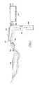
- the apparatus for the treatment of water to remove cyanobacteria comprises: a pump 10, a steel-lined bore hole 12 and a settling tank 14. Water from a lake or reservoir 16 is pumped by the pump 10 through a pipe 18 having an appropriate filter in its nozzle inlet section 20. The pumped water is passed to the bore-hole 12 via a pipe 22. As mentioned above the bore-hole 12 is lined with a steel lining to contain the water under pressure. A pipe 24 extends centrally down the bore-hole 12 to within a short distance from the bottom. Any other suitable lining material may be used instead of steel.
- the preferred depth of the bore-hole 12 is about 60m. However, the actual depth for any particular set of conditions is quite critical and has to be determined by experiment. Sufficient pressure must be generated, by the hydrostatic head at the bottom of pipe 24, to collapse enough gas vesicles to cause loss of the cyanobacteria's buoyancy. The minimum pressure required depends on the species of cyanobacterium present and may be from 3 bar to 10 bar. Since a pressure of 1 bar is generated by a vertical water column of 10.2m the required depth of pipe 24 below the surface is, correspondingly, about 31m to 102m. According to the nature of the cyanobacteria and the location, the preferred depth may therefore lie in the range of from 31m to 102m.
- the water from the reservoir 16 is thus pumped by the pump 10 down to the bottom of the pipe 24, where for a depth of 60m the hydrostatic pressure of the water at the bottom of the bore-hole 12 is approximately 6 bar.
- the water which flows out of the top of the bore-hole 12 is passed to the settling tank 14 by means of a pipe 26.
- the construction of the bore-hole 12 is shown in greater detail in Figure 2.
- the bore-hole 12 After the bore-hole 12 has been dug in the ground it is sealed against penetration of liquid from the ground by being steel lined with a series of plates 13 or annular rings which are welded together.
- a circular steel plate 15 is provided at the bottom of the bore-hole 12.
- the pipe 22 from the pump 10 is connected to the centrally located vertical pipe 24 by means of an elbow joint 28 and flanges 30 and 32.
- the pipe 24 is centrally located within the steel-lined bore-hole by means of locating spiders 34 which are provided at equi-spaced intervals from top to bottom of the bore-hole 12.
- water from the lake or reservoir 16 containing cyanobacteria is pumped to the bottom of the bore-hole 12 by means of the pipe 24, where the hydrostatic pessure builds up to about 6 bar.
- This pressure is sufficient to collapse the gas vesicles in the cyanobacteria, so that when they are carried out of the bore-hole 12 and into the settling tank 14 via the pipe 26, their specific gravity is now greater than unity so that they sink with the other sludge and foreign bodies to the bottom of the settling tank leaving clean treated water at the top of the settling tank from which it can be drawn for further treatment before being supplied to the customer.
- FIG. 3 A first alternative construction is shown in Figure 3, wherein the height of the level of the lake or reservoir is above the location of the treatment apparatus and part of the hydrostatic head can be supplied by the difference in vertical level between the reservoir surface and the top of the bore-hole or between the top of a tower 44 and the top of a bore-hole 40. The required depth of the bore-hole 40 is reduced accordingly.
- water from a reservoir 16 is pumped up to the top of a tower 44 by means of the pump 10 through a pipe 46.
- the bottom of the tower 44 is connected to the pipe 24 of the bore-hole 40 by a pipe 42.
- Water is pumped into the top of the tower through the pipe 46 at a rate so as to maintain the level of water near the top of the tower 44.
- the desired pressure of 6 bar can be produced by ensuring that the total head between the top of the tower 44 and the bottom of the pipe 24 is 60m.
- FIG. 4 A second alternative construction is shown in Figure 4 in which the pressure necessary to collapse the gas vesicles inside the cells of the cyanobacteria can be generated in a water container or pipe.
- a pump 50 takes water from the reservoir 16 via the pipe 18 and supplies it to a horizontal cylindrical container or pipe 52 which is provided with a diffuser or pressure relief valve 54 at the other end. Water passing through the valve 54 is collected in the settling tank 14. The pressure which builds up in the container or pipe 52 is sufficient to collapse the gas vesicles inside the cells of the cyanobacteria which then sink to the bottom of the settling tank 14.
- a combination of the constructions shown in Figure 3 and 4 is possible.
- the same method and apparatus could be used to decrease the amount of cyanobacteria that contain gas vesicles in natural lakes or other water impoundments, and thereby to improve the water quality.
- the pressure-treated water is returned to the lake either directly from the bore-hole, in which case the cyanobacteria will settle out on the lake bottom, or after removing the cyanobacteria by sedimentation in a settling tank.
- the preferred method would be to withdraw water from a particular depth at one end of the lake and to return it after treatment to the lake at another depth at a point remote from the withdrawal site, so as to minimize mixing of the treated and untreated water.
- Regard would be paid to the patterns of water circulation in the lake so that withdrawal occurred at a site, such as at lee shores, where the cyanobacteria tended to accumulate.
Landscapes
- Life Sciences & Earth Sciences (AREA)
- Engineering & Computer Science (AREA)
- Hydrology & Water Resources (AREA)
- Environmental & Geological Engineering (AREA)
- Water Supply & Treatment (AREA)
- Chemical & Material Sciences (AREA)
- Organic Chemistry (AREA)
- Microbiology (AREA)
- Botany (AREA)
- Biodiversity & Conservation Biology (AREA)
- Biotechnology (AREA)
- Physical Water Treatments (AREA)
- Aeration Devices For Treatment Of Activated Polluted Sludge (AREA)
- Removal Of Specific Substances (AREA)
- Treating Waste Gases (AREA)
- Water Treatment By Sorption (AREA)
- Separation Of Suspended Particles By Flocculating Agents (AREA)
- Separation Using Semi-Permeable Membranes (AREA)
- Mechanical Treatment Of Semiconductor (AREA)
- Electrical Discharge Machining, Electrochemical Machining, And Combined Machining (AREA)
- Cultivation Of Seaweed (AREA)
Claims (9)
- Vorrichtung zur Behandlung von Wasser zum Entfernen von Gasvakuolen aufweisenden Zyanobakterien, die auf der Wasseroberfläche schwimmen, wobei die genannte Vorrichtung umfaßt:
eine Pumpeinrichtung (10) zum Abziehen des zu behandelnden Wassers von einem Reservoir (16);
ein in den Boden versenktes, mit Stahl ausgekleidetes Bohrloch (12);
ein in der Mitte angeordnetes vertikales Rohr (24), das im genannten Bohrloch enthalten ist und dessen unteres Ende offen und in einem kurzen Abstand über dem Boden des Bohrlochs angeordnet ist;
eine Rohreinrichtung (22) zum Verbinden des Oberteils des genannten in der Mitte angeordnetes Rohres mit dem Auslaß der genannten Pumpeinrichtung, wobei die Tiefe des genannten Bohrlochs ausreicht, um es zu ermöglichen, daß die im genannten in der Mitte angeordneten Rohr enthaltene natürliche hydrostatische Wassersäule genügend Druck erzeugt, um die Gasbläschen innerhalb der Zellen der Zyanobakterien zu zerdrücken;
einen in Nachbarschaft des genannten Bohrlochs angeordneten Absetztank (14);
und eine Rohreinrichtung (26), die das obere Ende des Bohrlochs mit dem Absetztank verbindet, um Wasser, welches das in der Mitte angeordnete Rohr in Abwärtsrichtung passiert hat, zum Absetztank zu befördern, wodurch sich die zerdrückte Gasvakuolen aufweisenden Zyanobakterien am Boden des Absetztanks absetzen und somit eine Wasserabströmung des Absetztanks geschaffen wird, die frei von Gasvakuolen aufweisenden Zyanobakterien ist. - Vorrichtung nach Anspruch 1, worin die Tiefe des Bohrlochs (12) im Bereich von 31 m bis 102 m liegt.
- Vorrichtung nach Anspruch 1, worin der von der hydrostatischen Wassersäule erzeugte genannte Druck am Boden des Bohrlochs (12) im Bereich von 3 bis 10 bar liegt.
- Vorrichtung nach Anspruch 1, worin der genannte von der hydrostatischen Wassersäule erzeugte Druck am Boden des Bohrlochs (12) etwa 6 bar beträgt.
- Vorrichtung nach Anspruch 1, worin im wesentlichen der gesamte Druck, der angewandt wird, um die Gasvakuolen aufweisenden Zyanobakterien zu zerdrücken, vom Bohrloch und der im genannten in der Mitte angeordneten Rohr enthaltenen hydrostatischen Wassersäule kommt.
- Vorrichtung zur Behandlung von Wasser zum Entfernen von Gasvakuolen aufweisenden Zyanobakterien, die auf der Wasseroberfläche schwimmen, wobei die genannte Vorrichtung umfaßt:
eine Pumpeinrichtung (10) zum Abziehen des zu behandelnden Wassers von einem Reservoir;
einen Turm (44) mit einer Einlaßeinrichtung (46) am Oberteil, die mit dem Auslaß der Pumpeinrichtung verbunden ist, und einer Auslaßeinrichtung am Boden;
ein in den Boden versenktes, mit Stahl ausgekleidetes Bohrloch (40);
ein Rohr (24), das sich im mittleren Bereich des genannten Bohrlochs vertikal nach unten erstreckt;
eine Rohreinrichtung (42), welche die Auslaßeinrichtung des Turms (44) mit dem Oberteil des sich das Bohrloch (40) hinunter erstreckenden Rohres (24) verbindet;
eine Auslaßeinrichtung (26) am Oberteil des Bohrlochs;
und einen Absetztank (14), der verbunden ist, um Wasser von der Auslaßeinrichtung des Bohrlochs aufzunehmen; wobei die kombinierte Höhe des Turmes und Tiefe des Bohrlochs ausreichen, um es zu ermöglichen, daß die vom genannten Turm und Bohrloch geschaffene natürliche hydrostatische Wassersäule genügend Druck erzeugt, um die Gasbläschen innerhalb der Zyanobakterienzellen zusammenzudrücken, wodurch sich die zusammengedrückte Gasvakuolen aufweisenden Zyanobakterien am Boden des Absetztanks absetzen, wodurch eine Wasserabströmung vom Absetztank geschaffen wird, die frei von Gasvakuolen aufweisenden Zyanobakterien ist. - Vorrichtung nach Anspruch 6, worin die von der kombinierten Höhe des Turms (44) und Tiefe des Bohrlochs (12) geschaffene Wassersäule 60 m hoch ist, um einen Druck von 6 bar zu erzeugen.
- Vorrichtung nach Anspruch 6, worin im wesentlichen der gesamte Druck, der angewandt wird, um die Gasvakuolen aufweisenden Zyanobakterien zusammenzudrücken, vom Bohrloch und der natürlichen hydrostatischen Wassersäule stammt, die in dem genannten in der Mitte angeordneten Rohr (24), dem genannten Turm (44) und der verbindenden Rohreinrichtung (42) enthalten ist.
- Vorrichtung nach Anspruch 6, dadurch gekennzeichnet, daß sie zusätzlich in Kombination mit dem Turm (44) und dem Bohrloch (40) eine Pumpe (50), einen Wasserbehälter (52), dessen eines Ende mit der Pumpe verbunden ist, und ein Diffusor- oder Überdruckventil (54), einschließt, das mit dem anderen Ende des Behälters verbunden ist, durch den das zu behandelnde Wasser unter hydrostatischem Druck hindurchgeht.
Priority Applications (1)
| Application Number | Priority Date | Filing Date | Title |
|---|---|---|---|
| AT87308442T ATE78006T1 (de) | 1986-09-30 | 1987-09-24 | Einrichtung zur entfernung von glasblaeschen enthaltenden zyanobakterien aus wasser. |
Applications Claiming Priority (2)
| Application Number | Priority Date | Filing Date | Title |
|---|---|---|---|
| GB8623428 | 1985-09-20 | ||
| GB868623428A GB8623428D0 (en) | 1986-09-30 | 1986-09-30 | Treatment of water |
Publications (3)
| Publication Number | Publication Date |
|---|---|
| EP0262865A2 EP0262865A2 (de) | 1988-04-06 |
| EP0262865A3 EP0262865A3 (en) | 1989-11-02 |
| EP0262865B1 true EP0262865B1 (de) | 1992-07-08 |
Family
ID=10604996
Family Applications (1)
| Application Number | Title | Priority Date | Filing Date |
|---|---|---|---|
| EP87308442A Expired - Lifetime EP0262865B1 (de) | 1986-09-30 | 1987-09-24 | Einrichtung zur Entfernung von Glasbläschen enthaltenden Zyanobakterien aus Wasser |
Country Status (11)
| Country | Link |
|---|---|
| EP (1) | EP0262865B1 (de) |
| AT (1) | ATE78006T1 (de) |
| AU (1) | AU595645B2 (de) |
| CA (1) | CA1327654C (de) |
| DE (1) | DE3780244T2 (de) |
| ES (1) | ES2033864T3 (de) |
| GB (2) | GB8623428D0 (de) |
| GR (1) | GR3005879T3 (de) |
| IL (1) | IL84048A (de) |
| NO (1) | NO168760C (de) |
| ZA (1) | ZA877185B (de) |
Families Citing this family (4)
| Publication number | Priority date | Publication date | Assignee | Title |
|---|---|---|---|---|
| AU2003276624B2 (en) * | 2002-10-24 | 2009-09-10 | Pan Pacific Technologies, Pty Ltd | Method and system for removal of contaminants from aqueous solution |
| CN107265526A (zh) * | 2017-07-18 | 2017-10-20 | 无锡德林海环保科技股份有限公司 | 蓝藻深井处理设备及蓝藻处理方法 |
| CN107226494A (zh) * | 2017-07-18 | 2017-10-03 | 无锡德林海环保科技股份有限公司 | 一种蓝藻深井灭藻设备及其蓝藻处理方法 |
| CN114699990B (zh) * | 2022-03-16 | 2024-09-20 | 南京玄武高新技术产业集团有限公司 | 一种静压力输水控制系统及其控制方法 |
Family Cites Families (2)
| Publication number | Priority date | Publication date | Assignee | Title |
|---|---|---|---|---|
| US3606999A (en) * | 1967-08-04 | 1971-09-21 | Harold L Lawless | Method of and apparatus for carrying out a chemical or physical process |
| EP0040887B1 (de) * | 1980-05-22 | 1984-03-21 | Jan Schmidt | Verfahren und Vorrichtung für die Behandlung und Hygienisierung von Abwasserschlamm und anderen organischen Schlämmen |
-
1986
- 1986-09-30 GB GB868623428A patent/GB8623428D0/en active Pending
-
1987
- 1987-09-22 CA CA000547542A patent/CA1327654C/en not_active Expired - Fee Related
- 1987-09-23 GB GB8722378A patent/GB2196330B/en not_active Expired - Fee Related
- 1987-09-24 EP EP87308442A patent/EP0262865B1/de not_active Expired - Lifetime
- 1987-09-24 DE DE8787308442T patent/DE3780244T2/de not_active Expired - Fee Related
- 1987-09-24 ES ES198787308442T patent/ES2033864T3/es not_active Expired - Lifetime
- 1987-09-24 AT AT87308442T patent/ATE78006T1/de not_active IP Right Cessation
- 1987-09-24 ZA ZA877185A patent/ZA877185B/xx unknown
- 1987-09-29 NO NO874087A patent/NO168760C/no not_active IP Right Cessation
- 1987-09-30 AU AU79204/87A patent/AU595645B2/en not_active Ceased
- 1987-09-30 IL IL84048A patent/IL84048A/xx unknown
-
1992
- 1992-10-01 GR GR920402211T patent/GR3005879T3/el unknown
Also Published As
| Publication number | Publication date |
|---|---|
| AU595645B2 (en) | 1990-04-05 |
| DE3780244T2 (de) | 1993-01-07 |
| AU7920487A (en) | 1988-04-14 |
| EP0262865A2 (de) | 1988-04-06 |
| DE3780244D1 (de) | 1992-08-13 |
| NO874087D0 (no) | 1987-09-29 |
| CA1327654C (en) | 1994-03-08 |
| ES2033864T3 (es) | 1993-04-01 |
| ZA877185B (en) | 1989-05-30 |
| IL84048A0 (en) | 1988-02-29 |
| IL84048A (en) | 1991-04-15 |
| NO168760B (no) | 1991-12-23 |
| ATE78006T1 (de) | 1992-07-15 |
| EP0262865A3 (en) | 1989-11-02 |
| GR3005879T3 (de) | 1993-06-07 |
| NO874087L (no) | 1988-04-05 |
| GB8722378D0 (en) | 1987-10-28 |
| NO168760C (no) | 1992-04-01 |
| GB2196330A (en) | 1988-04-27 |
| GB8623428D0 (en) | 1986-11-05 |
| GB2196330B (en) | 1990-04-04 |
Similar Documents
| Publication | Publication Date | Title |
|---|---|---|
| US4536286A (en) | Mobile waste water and sludge treatment for hazardous and non-hazardous fluids | |
| US6800201B2 (en) | Seawater pressure-driven desalinization method using a gravity-driven brine return | |
| US4293421A (en) | Method and equipment for a wrap-around upflow submerged anaerobic filter for sewage | |
| AU2005262928B2 (en) | Desalination apparatus and method | |
| KR101933631B1 (ko) | 유류오염 지하수의 추출, 정화 및 재주입 시스템 | |
| US5422002A (en) | Treatment of water to remove gas vacuolate cyanobacteria | |
| EP0262865B1 (de) | Einrichtung zur Entfernung von Glasbläschen enthaltenden Zyanobakterien aus Wasser | |
| CN102834361A (zh) | 废水处理的方法和在间歇式反应器中用于实现该方法的装置 | |
| US6224770B1 (en) | Biowall for groundwater remediation | |
| US20250146266A1 (en) | Systems and methods for underground storage of storm and other water sources | |
| DE2357707A1 (de) | Einrichtung zur behandlung und beseitigung von abwaessern | |
| US3649531A (en) | Dewatering of digested sludge | |
| US6428239B1 (en) | Vadose zone for a leaching field | |
| RU2150434C1 (ru) | Установка опреснения морской воды и способ опреснения морской воды | |
| SU1625925A1 (ru) | Устройство дл осветлени технологической воды при намыве сооружени | |
| CN108002665A (zh) | 污水处理装置及污水处理系统 | |
| SU1247352A1 (ru) | Способ очистки сточных вод | |
| CA3021314C (en) | Oil sands tailings ponds water disposal | |
| Christoulas et al. | A system for on site treatment and disposal of wastewaters from tourist resorts | |
| US9512015B2 (en) | Method and system for water treatment | |
| JP2862820B2 (ja) | 土砂礫等を含む泥水の分離方法および装置 | |
| JPS6330556Y2 (de) | ||
| WO1988000857A1 (en) | Method and apparatus for filtration using washable filter bag for water and wastewater treatment | |
| CN1255459A (zh) | 公共污水处理设备 | |
| DE2137716A1 (de) | Verfahren zur reinigung von verschlammten gewaessern |
Legal Events
| Date | Code | Title | Description |
|---|---|---|---|
| PUAI | Public reference made under article 153(3) epc to a published international application that has entered the european phase |
Free format text: ORIGINAL CODE: 0009012 |
|
| AK | Designated contracting states |
Kind code of ref document: A2 Designated state(s): AT BE CH DE ES FR GB GR IT LI LU NL SE |
|
| PUAL | Search report despatched |
Free format text: ORIGINAL CODE: 0009013 |
|
| AK | Designated contracting states |
Kind code of ref document: A3 Designated state(s): AT BE CH DE ES FR GB GR IT LI LU NL SE |
|
| 17P | Request for examination filed |
Effective date: 19900205 |
|
| 17Q | First examination report despatched |
Effective date: 19901127 |
|
| GRAA | (expected) grant |
Free format text: ORIGINAL CODE: 0009210 |
|
| AK | Designated contracting states |
Kind code of ref document: B1 Designated state(s): AT BE CH DE ES FR GB GR IT LI LU NL SE |
|
| REF | Corresponds to: |
Ref document number: 78006 Country of ref document: AT Date of ref document: 19920715 Kind code of ref document: T |
|
| RAP2 | Party data changed (patent owner data changed or rights of a patent transferred) |
Owner name: WALSBY, ANTHONY EDWARD Owner name: SUFFOLK WATER PLC |
|
| REF | Corresponds to: |
Ref document number: 3780244 Country of ref document: DE Date of ref document: 19920813 |
|
| ITF | It: translation for a ep patent filed | ||
| ET | Fr: translation filed | ||
| REG | Reference to a national code |
Ref country code: GR Ref legal event code: FG4A Free format text: 3005879 |
|
| REG | Reference to a national code |
Ref country code: ES Ref legal event code: FG2A Ref document number: 2033864 Country of ref document: ES Kind code of ref document: T3 |
|
| PLBE | No opposition filed within time limit |
Free format text: ORIGINAL CODE: 0009261 |
|
| STAA | Information on the status of an ep patent application or granted ep patent |
Free format text: STATUS: NO OPPOSITION FILED WITHIN TIME LIMIT |
|
| 26N | No opposition filed | ||
| EPTA | Lu: last paid annual fee | ||
| EAL | Se: european patent in force in sweden |
Ref document number: 87308442.0 |
|
| PGFP | Annual fee paid to national office [announced via postgrant information from national office to epo] |
Ref country code: GR Payment date: 20000810 Year of fee payment: 14 |
|
| PGFP | Annual fee paid to national office [announced via postgrant information from national office to epo] |
Ref country code: ES Payment date: 20000818 Year of fee payment: 14 |
|
| PGFP | Annual fee paid to national office [announced via postgrant information from national office to epo] |
Ref country code: GB Payment date: 20000914 Year of fee payment: 14 |
|
| PGFP | Annual fee paid to national office [announced via postgrant information from national office to epo] |
Ref country code: FR Payment date: 20000920 Year of fee payment: 14 |
|
| PGFP | Annual fee paid to national office [announced via postgrant information from national office to epo] |
Ref country code: SE Payment date: 20000921 Year of fee payment: 14 Ref country code: DE Payment date: 20000921 Year of fee payment: 14 Ref country code: CH Payment date: 20000921 Year of fee payment: 14 |
|
| PGFP | Annual fee paid to national office [announced via postgrant information from national office to epo] |
Ref country code: LU Payment date: 20000925 Year of fee payment: 14 Ref country code: AT Payment date: 20000925 Year of fee payment: 14 |
|
| PGFP | Annual fee paid to national office [announced via postgrant information from national office to epo] |
Ref country code: NL Payment date: 20000926 Year of fee payment: 14 |
|
| PGFP | Annual fee paid to national office [announced via postgrant information from national office to epo] |
Ref country code: BE Payment date: 20000927 Year of fee payment: 14 |
|
| PG25 | Lapsed in a contracting state [announced via postgrant information from national office to epo] |
Ref country code: LU Free format text: LAPSE BECAUSE OF NON-PAYMENT OF DUE FEES Effective date: 20010924 Ref country code: GB Free format text: LAPSE BECAUSE OF NON-PAYMENT OF DUE FEES Effective date: 20010924 Ref country code: AT Free format text: LAPSE BECAUSE OF NON-PAYMENT OF DUE FEES Effective date: 20010924 |
|
| PG25 | Lapsed in a contracting state [announced via postgrant information from national office to epo] |
Ref country code: SE Free format text: LAPSE BECAUSE OF NON-PAYMENT OF DUE FEES Effective date: 20010925 Ref country code: ES Free format text: LAPSE BECAUSE OF NON-PAYMENT OF DUE FEES Effective date: 20010925 |
|
| PG25 | Lapsed in a contracting state [announced via postgrant information from national office to epo] |
Ref country code: LI Free format text: LAPSE BECAUSE OF NON-PAYMENT OF DUE FEES Effective date: 20010930 Ref country code: GR Free format text: LAPSE BECAUSE OF NON-PAYMENT OF DUE FEES Effective date: 20010930 Ref country code: CH Free format text: LAPSE BECAUSE OF NON-PAYMENT OF DUE FEES Effective date: 20010930 Ref country code: BE Free format text: LAPSE BECAUSE OF NON-PAYMENT OF DUE FEES Effective date: 20010930 |
|
| REG | Reference to a national code |
Ref country code: GB Ref legal event code: IF02 |
|
| BERE | Be: lapsed |
Owner name: WALSBY ANTHONY EDWARD Effective date: 20010930 Owner name: SUFFOLK WATER P.L.C. Effective date: 20010930 |
|
| PG25 | Lapsed in a contracting state [announced via postgrant information from national office to epo] |
Ref country code: NL Free format text: LAPSE BECAUSE OF NON-PAYMENT OF DUE FEES Effective date: 20020401 |
|
| PG25 | Lapsed in a contracting state [announced via postgrant information from national office to epo] |
Ref country code: DE Free format text: LAPSE BECAUSE OF NON-PAYMENT OF DUE FEES Effective date: 20020501 |
|
| EUG | Se: european patent has lapsed |
Ref document number: 87308442.0 |
|
| GBPC | Gb: european patent ceased through non-payment of renewal fee |
Effective date: 20010924 |
|
| REG | Reference to a national code |
Ref country code: CH Ref legal event code: PL |
|
| PG25 | Lapsed in a contracting state [announced via postgrant information from national office to epo] |
Ref country code: FR Free format text: LAPSE BECAUSE OF NON-PAYMENT OF DUE FEES Effective date: 20020531 |
|
| NLV4 | Nl: lapsed or anulled due to non-payment of the annual fee |
Effective date: 20020401 |
|
| REG | Reference to a national code |
Ref country code: FR Ref legal event code: ST |
|
| NLV4 | Nl: lapsed or anulled due to non-payment of the annual fee |
Effective date: 20020401 |
|
| REG | Reference to a national code |
Ref country code: ES Ref legal event code: FD2A Effective date: 20021011 |
|
| PG25 | Lapsed in a contracting state [announced via postgrant information from national office to epo] |
Ref country code: IT Free format text: LAPSE BECAUSE OF NON-PAYMENT OF DUE FEES Effective date: 20050924 |