EP0262866A2 - Betätigungseinrichtung für Bremsen - Google Patents
Betätigungseinrichtung für Bremsen Download PDFInfo
- Publication number
- EP0262866A2 EP0262866A2 EP87308445A EP87308445A EP0262866A2 EP 0262866 A2 EP0262866 A2 EP 0262866A2 EP 87308445 A EP87308445 A EP 87308445A EP 87308445 A EP87308445 A EP 87308445A EP 0262866 A2 EP0262866 A2 EP 0262866A2
- Authority
- EP
- European Patent Office
- Prior art keywords
- wedge
- drive device
- force
- actuator according
- tappets
- Prior art date
- Legal status (The legal status is an assumption and is not a legal conclusion. Google has not performed a legal analysis and makes no representation as to the accuracy of the status listed.)
- Withdrawn
Links
- 230000005540 biological transmission Effects 0.000 claims description 7
- 230000015572 biosynthetic process Effects 0.000 claims description 6
- 230000007246 mechanism Effects 0.000 claims description 6
- 238000006073 displacement reaction Methods 0.000 claims description 4
- 230000008878 coupling Effects 0.000 claims description 3
- 238000010168 coupling process Methods 0.000 claims description 3
- 238000005859 coupling reaction Methods 0.000 claims description 3
- 230000000452 restraining effect Effects 0.000 claims 1
- 238000005755 formation reaction Methods 0.000 description 5
- 230000009471 action Effects 0.000 description 3
- 230000004075 alteration Effects 0.000 description 1
- 238000010276 construction Methods 0.000 description 1
- 230000000694 effects Effects 0.000 description 1
- 230000004044 response Effects 0.000 description 1
- 230000000717 retained effect Effects 0.000 description 1
Images

Classifications
-
- F—MECHANICAL ENGINEERING; LIGHTING; HEATING; WEAPONS; BLASTING
- F16—ENGINEERING ELEMENTS AND UNITS; GENERAL MEASURES FOR PRODUCING AND MAINTAINING EFFECTIVE FUNCTIONING OF MACHINES OR INSTALLATIONS; THERMAL INSULATION IN GENERAL
- F16D—COUPLINGS FOR TRANSMITTING ROTATION; CLUTCHES; BRAKES
- F16D65/00—Parts or details
- F16D65/38—Slack adjusters
- F16D65/40—Slack adjusters mechanical
- F16D65/52—Slack adjusters mechanical self-acting in one direction for adjusting excessive play
- F16D65/56—Slack adjusters mechanical self-acting in one direction for adjusting excessive play with screw-thread and nut
- F16D65/561—Slack adjusters mechanical self-acting in one direction for adjusting excessive play with screw-thread and nut for mounting within the confines of a drum brake
- F16D65/562—Slack adjusters mechanical self-acting in one direction for adjusting excessive play with screw-thread and nut for mounting within the confines of a drum brake arranged between service brake actuator and braking member, and subjected to service brake force
-
- F—MECHANICAL ENGINEERING; LIGHTING; HEATING; WEAPONS; BLASTING
- F16—ENGINEERING ELEMENTS AND UNITS; GENERAL MEASURES FOR PRODUCING AND MAINTAINING EFFECTIVE FUNCTIONING OF MACHINES OR INSTALLATIONS; THERMAL INSULATION IN GENERAL
- F16D—COUPLINGS FOR TRANSMITTING ROTATION; CLUTCHES; BRAKES
- F16D65/00—Parts or details
- F16D65/14—Actuating mechanisms for brakes; Means for initiating operation at a predetermined position
- F16D65/16—Actuating mechanisms for brakes; Means for initiating operation at a predetermined position arranged in or on the brake
- F16D65/22—Actuating mechanisms for brakes; Means for initiating operation at a predetermined position arranged in or on the brake adapted for pressing members apart, e.g. for drum brakes
-
- F—MECHANICAL ENGINEERING; LIGHTING; HEATING; WEAPONS; BLASTING
- F16—ENGINEERING ELEMENTS AND UNITS; GENERAL MEASURES FOR PRODUCING AND MAINTAINING EFFECTIVE FUNCTIONING OF MACHINES OR INSTALLATIONS; THERMAL INSULATION IN GENERAL
- F16D—COUPLINGS FOR TRANSMITTING ROTATION; CLUTCHES; BRAKES
- F16D2125/00—Components of actuators
- F16D2125/18—Mechanical mechanisms
- F16D2125/58—Mechanical mechanisms transmitting linear movement
- F16D2125/66—Wedges
Definitions
- This invention relates to a brake actuator, primarily for use in a vehicle braking system, and being of the general kind in which force-applying means is arranged to separate opposed tappets which transmit thrust from said means to braking elements engaged, in use, by the tappets.
- the wedge actuates a yoke which is supported for sliding movement on a pivoted shaft and forms a pair of racks engaging respective toothed wheels operatively associated with the tappets, the racks performing a generally linear movement and engaging successive teeth on said wheels in order to rotate the wheels and cause adjustment of the tappets.
- This arrangement is not only excessively complicated, but potentially unreliable because of possible jamming of the various sliding and pivoting parts.
- An object of the present invention is to provide a brake actuator of the aforesaid general kind which incorporates an improved adjuster mechanism of simple and reliable construction capable of adjusting both tappets simultaneously.
- a brake actuator comprises force-applying means arranged to separate opposed tappets which transmit thrust from said means to braking elements engaged, in use, by the tappets, each tappet including a pair of threadedly interengaged members forming an extensible strut, a drive device connected to the force-applying means in such a manner as to be displaced by actuating movement of said means, transmission means drivingly coupling said drive device, for one direction of displacement, to a pair of interconnected driving elements each permanently engaged with respective ones of the interengaged strut members of each strut, whereby said displacement of the drive device resulting from actuating movement of the force-applying means in one direction is transmitted via said driving elements to said interengaged strut members to extend the struts simultaneously.
- the drive device comprises a first part, conveniently in the form of a pinion, actuated by the force-applying means and a second part coupled to the first part by second transmission means, conveniently in the form of a multi-plate clutch, which ceases to drive upon application by said force-applying means to the first part of the drive device of a force exceeding a predetermined value, thereby preventing operation of the adjuster during the continuance of said excessive force.
- the operation of the adjuster is thus rendered load insensitive.
- At least said driving elements and the strut members engaged thereby are interengaged by way of non-helical toothed formations.
- Some known adjusters using helical and other inclined formations for this purpose are subject to the occurrence of small random alterations of the adjuster settings due to spurious forces generated in the adjuster components by vibrational forces transmitted through said inclined formations. The aforesaid use of non-helical formations minimises this problem in the adjuster of the invention.
- the internal shoe drum brake illustrated in Figure 1 of the drawings includes a pair of brake shoes 1, 2 mounted on a stationary backplate 3 which also carries a wedge and roller actuator 4 disposed between one pair of adjacent shoe ends and operable to urge the shoes outwardly into braking engagement with a brake drum (not shown) against the opposing action of a pair of shoe return springs 5, 6.
- the other adjacent shoe ends engage an abutment 7 which is secured to or integral with the backplate 3 and permits a degree of pivotal and sliding movement of the shoes, during actuation, in conventional manner.
- the brake illustrated is of leading/trailing configuration with the shoes 1 and 2 acting in leading and trailing modes respectively for a brake rotational direction indicated by the arrow 'R'.
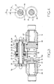
- the actuator 4 may conveniently be in the form illustrated in Figure 2 of the drawings, having a body 8 with an axial through bore 9 divided into bore portions 9A, 9B which are intersected by a transverse bore 10 extending at right angles to the bore 9.
- the bore 9 contains a pair of opposed tappets 11, 12 disposed respectively in the bore portions 9A, 9B, the tappets being normally engaged, in use, respectively with the brake shoes 1, 2 which are engagable in slots 11A, 12A of the tappets and thereby prevent rotation of the engaged tappet parts.
- Brake actuating forces are applied to the shoes via the tappets by means of a force-applying means in the form of a wedge device 13 which includes a wedge 14 fast with and reciprocal by means of an actuating rod 15, the wedge being located between a pair of rollers 16, 17 carried by a cage 18 mounted on the rod 15.
- the rollers 16, 17, are disposed respectively between actuating surfaces 14A, 14B of the wedge and opposed surfaces 11B, 12B of the tappets, the angles of inclination of these surfaces relative to the longitudinal axis A of the wedge being preferably, although not essentially, the same.
- the roller 16 also engages a fixed surface 19A, formed in this embodiment on an insert 19 secured to the body 1, although it may be formed on an internal surface of the body proper, should this be convenient in practice.
- the wedge 14 when urged in the direction of the arrow in Figure 2, actuates the tappets 11, 12 via the rollers 16, 17 in conventional manner. Since the roller 16 also bears on the inclined fixed surface 19A, any forces which would otherwise be transmitted from the trailing shoe tappet 12 to the leading shoe tappet 11 during actuation of the tappets are instead reacted on the insert 19 at the surface 19A. The wedge is thereby constrained to move in a substantially linear manner.
- the tappets are adjusted simultaneously by a single common adjuster mechanism indicated generally at 20, which will now be described in detail.
- the adjuster includes a primary pinion 21 which meshes with a toothed rack 14C formed on a facing surface of the wedge 14, the aforesaid linear restraint of the wedge enabling it to be maintained in permanent engagement with the pinion 21.
- the pinion 21 is being freely rotatably mounted on a cylindrical coaxial sleeve 22 which has a radial flange 23 between which and an opposed surface of the pinion 21 is disposed a multi-plate friction clutch 24.
- the end face of the sleeve 22 at the opposite side of the clutch to the pinion 21 is formed with a slot 30 which receives a tongue 31 formed on an opposing face of a housing 32.
- the housing contains a sprag clutch 33 in the form of a coiled square-section spring acting between the housing 32 and a secondary pinion 34 mounted on and fast for rotation with a shaft 35 extending coaxially through the sleeve 22 and mounting, at its opposite end, a further secondary pinion 36 also fast for rotation with the shaft.
- the shape of the slot 30 is such as to permit the sleeve 22 to move relative to the housing 32 through a predetermined angle ⁇ , the purpose of which will be explained hereinafter.
- the secondary pinions 34, 36 are externally toothed and engaged with corresponding toothed formations 37, 38 formed on the external surfaces of the respective tappets 11, 12.
- the teeth on the secondary pinions and tappets are parallel to the longitudinal axes about which these components rotate and effectively form a splined driving connection between the secondary pinions and tappets, permitting the tappets to move axially relative to the pinions during brake actuation.
- Each of the tappets 11, 12 is internally threaded and receives a respective adjuster shaft 39, 40, the respective pairs of tappets and shafts constituting struts of extendible length which are extended by operation of the aforesaid adjuster mechanism, in the manner to be described, in order to maintain a substantially constant predetermined clearance between the brake shoes engaging and actuated by the tappets and a braking surface such as the internal surface of a brake drum.
- the force exerted by the sprag clutch 33 whilst sufficient to overcome the partially relieved return spring load in the tappet threads during brake actuation, is such that it is less than the return spring force in those threads during retraction of the shoes and the clutch will therefore slip as the wedge returns to its fully retracted position without turning the tappets in the reverse direction.
- the purpose of the clutch 24 is to enable the adjuster to operate in a load insensitive manner.
- the force of the spring 27, which governs the frictional force built up in the clutch 24, is chosen so that no significant slipping of the clutch 24 occurs during the application of normal brake actuating forces to the shoes. In the event that such forces become large enough, for example, to initiate serious deflection of the brake components, the clutch 24 slips and the pinion 21 simply rotates on the sleeve 22, during the excessive load condition and thereby prevents the adjuster from adjusting in response such to brake component deflection.
- the clutch 24 may be omitted and the pinion 21 rendered permanently fast for rotation with the sleeve 22.
- the rack may alternatively be formed on or carried by the roller cage 18 or any other convenient movable component associated with the wedge assembly.
- the clearance between the slot 30 and tongue 31 may be omitted and the clearance provided between the rack 14 and pinion 21, or between that pinion and the sleeve 22 in the event that the pinion is drivingly connected to the shaft directly, rather than via the clutch 24.
- the actuator of the invention may be of any other convenient type; in one alternative form, the force-applying means may be a rotary cam arranged to separate a pair of tappets and operate a drive member to effect simultaneous automatic adjustment of the tappets.
Landscapes
- Engineering & Computer Science (AREA)
- General Engineering & Computer Science (AREA)
- Mechanical Engineering (AREA)
- Braking Arrangements (AREA)
Applications Claiming Priority (2)
| Application Number | Priority Date | Filing Date | Title |
|---|---|---|---|
| GB8623755 | 1986-10-03 | ||
| GB868623755A GB8623755D0 (en) | 1986-10-03 | 1986-10-03 | Brake actuator |
Publications (2)
| Publication Number | Publication Date |
|---|---|
| EP0262866A2 true EP0262866A2 (de) | 1988-04-06 |
| EP0262866A3 EP0262866A3 (de) | 1989-02-08 |
Family
ID=10605202
Family Applications (1)
| Application Number | Title | Priority Date | Filing Date |
|---|---|---|---|
| EP87308445A Withdrawn EP0262866A3 (de) | 1986-10-03 | 1987-09-24 | Betätigungseinrichtung für Bremsen |
Country Status (4)
| Country | Link |
|---|---|
| EP (1) | EP0262866A3 (de) |
| JP (1) | JPS63115926A (de) |
| BR (1) | BR8705239A (de) |
| GB (1) | GB8623755D0 (de) |
Family Cites Families (7)
| Publication number | Priority date | Publication date | Assignee | Title |
|---|---|---|---|---|
| US3869025A (en) * | 1972-10-10 | 1975-03-04 | Eaton Corp | Self-adjusting brake mechanism |
| FR2296795A1 (fr) * | 1975-01-03 | 1976-07-30 | Durand Francois | Mecanisme coin pistons |
| FR2296794A1 (fr) * | 1975-01-03 | 1976-07-30 | Durand Francois | Mecanisme coin pistons |
| GB2086500B (en) * | 1980-11-01 | 1985-05-15 | Lucas Industries Ltd | Brake adjustment specifically for vehicle drum brakes |
| GB8324942D0 (en) * | 1983-09-17 | 1983-10-19 | Lucas Ind Plc | Actuator assemblies for vehicle brakes |
| SE455635B (sv) * | 1985-05-10 | 1988-07-25 | Garphyttan Haldex Ab | Styranordning for en tryckstang till en bromscylinder vid ett kilbromsarrangemang |
| US4623047A (en) * | 1985-11-15 | 1986-11-18 | Eaton Corporation | Automatic brake adjustment assembly |
-
1986
- 1986-10-03 GB GB868623755A patent/GB8623755D0/en active Pending
-
1987
- 1987-09-24 EP EP87308445A patent/EP0262866A3/de not_active Withdrawn
- 1987-10-02 JP JP62249670A patent/JPS63115926A/ja active Pending
- 1987-10-02 BR BR8705239A patent/BR8705239A/pt unknown
Also Published As
| Publication number | Publication date |
|---|---|
| JPS63115926A (ja) | 1988-05-20 |
| EP0262866A3 (de) | 1989-02-08 |
| BR8705239A (pt) | 1988-05-24 |
| GB8623755D0 (en) | 1986-11-05 |
Similar Documents
| Publication | Publication Date | Title |
|---|---|---|
| US4351419A (en) | Automatic slack adjuster | |
| USRE26965E (en) | Automatic slack adjuster for vehicle brakes | |
| JP3642800B2 (ja) | S型カム自動車用制動器の制動レバー | |
| US4454933A (en) | Disc brake | |
| US4394890A (en) | Automatic slack adjuster | |
| JPH0726652B2 (ja) | 自動式ゆるみ調節装置 | |
| US3967705A (en) | Application adjuster for disc brake | |
| US5794738A (en) | Disc brake with gear driven adjusting piston | |
| US4491203A (en) | Power screw disc brake with internal automatic slack adjuster | |
| CN106574678A (zh) | 用于盘式制动器的制动启动机构和包括制动启动机构的盘式制动器 | |
| US4499976A (en) | Slack adjuster for a disc brake | |
| JPH026932B2 (de) | ||
| EP0262866A2 (de) | Betätigungseinrichtung für Bremsen | |
| EP0261903A2 (de) | Betätigungseinrichtung mit Spreizkeil und Rollen | |
| EP0120883B1 (de) | Nachstellvorrichtung für eine bremse | |
| WO1998021498A1 (en) | Disc brake with rigid connection between load plate and adjusting piston | |
| US4094390A (en) | Bidirectional clearance sensing brake adjuster | |
| US4702354A (en) | Brake actuator | |
| JPS59197633A (ja) | デイスクブレ−キのゆるみ調節装置 | |
| US4234064A (en) | Slack adjuster means | |
| EP0124754B1 (de) | Nachstelleinrichtung für eine Scheibenbremse | |
| US4620618A (en) | Brake shoe adjuster | |
| EP0410598A1 (de) | Bremsbetätigungsvorrichtung | |
| DE3445564A1 (de) | Nachstellvorrichtung fuer eine scheibenbremse, insbesondere fuer kraftfahrzeuge | |
| EP0471496A1 (de) | Automatischer Bremsen-Nachsteller |
Legal Events
| Date | Code | Title | Description |
|---|---|---|---|
| PUAI | Public reference made under article 153(3) epc to a published international application that has entered the european phase |
Free format text: ORIGINAL CODE: 0009012 |
|
| AK | Designated contracting states |
Kind code of ref document: A2 Designated state(s): DE FR GB IT |
|
| PUAL | Search report despatched |
Free format text: ORIGINAL CODE: 0009013 |
|
| AK | Designated contracting states |
Kind code of ref document: A3 Designated state(s): DE FR GB IT |
|
| STAA | Information on the status of an ep patent application or granted ep patent |
Free format text: STATUS: THE APPLICATION IS DEEMED TO BE WITHDRAWN |
|
| 18D | Application deemed to be withdrawn |
Effective date: 19890809 |
|
| RIN1 | Information on inventor provided before grant (corrected) |
Inventor name: MARGETTS, HUGH GRENVILLE |