EP0262925A2 - Wandlerabschirmung - Google Patents
Wandlerabschirmung Download PDFInfo
- Publication number
- EP0262925A2 EP0262925A2 EP87308619A EP87308619A EP0262925A2 EP 0262925 A2 EP0262925 A2 EP 0262925A2 EP 87308619 A EP87308619 A EP 87308619A EP 87308619 A EP87308619 A EP 87308619A EP 0262925 A2 EP0262925 A2 EP 0262925A2
- Authority
- EP
- European Patent Office
- Prior art keywords
- transducer
- shield
- magnetic
- field sensing
- field
- Prior art date
- Legal status (The legal status is an assumption and is not a legal conclusion. Google has not performed a legal analysis and makes no representation as to the accuracy of the status listed.)
- Ceased
Links
Images



Classifications
-
- G—PHYSICS
- G11—INFORMATION STORAGE
- G11B—INFORMATION STORAGE BASED ON RELATIVE MOVEMENT BETWEEN RECORD CARRIER AND TRANSDUCER
- G11B5/00—Recording by magnetisation or demagnetisation of a record carrier; Reproducing by magnetic means; Record carriers therefor
- G11B5/127—Structure or manufacture of heads, e.g. inductive
- G11B5/33—Structure or manufacture of flux-sensitive heads, i.e. for reproduction only; Combination of such heads with means for recording or erasing only
- G11B5/39—Structure or manufacture of flux-sensitive heads, i.e. for reproduction only; Combination of such heads with means for recording or erasing only using magneto-resistive devices or effects
- G11B5/3903—Structure or manufacture of flux-sensitive heads, i.e. for reproduction only; Combination of such heads with means for recording or erasing only using magneto-resistive devices or effects using magnetic thin film layers or their effects, the films being part of integrated structures
- G11B5/3906—Details related to the use of magnetic thin film layers or to their effects
- G11B5/3912—Arrangements in which the active read-out elements are transducing in association with active magnetic shields, e.g. magnetically coupled shields
-
- G—PHYSICS
- G11—INFORMATION STORAGE
- G11B—INFORMATION STORAGE BASED ON RELATIVE MOVEMENT BETWEEN RECORD CARRIER AND TRANSDUCER
- G11B5/00—Recording by magnetisation or demagnetisation of a record carrier; Reproducing by magnetic means; Record carriers therefor
- G11B5/10—Structure or manufacture of housings or shields for heads
- G11B5/11—Shielding of head against electric or magnetic fields
-
- G—PHYSICS
- G11—INFORMATION STORAGE
- G11B—INFORMATION STORAGE BASED ON RELATIVE MOVEMENT BETWEEN RECORD CARRIER AND TRANSDUCER
- G11B5/00—Recording by magnetisation or demagnetisation of a record carrier; Reproducing by magnetic means; Record carriers therefor
- G11B5/127—Structure or manufacture of heads, e.g. inductive
- G11B5/33—Structure or manufacture of flux-sensitive heads, i.e. for reproduction only; Combination of such heads with means for recording or erasing only
- G11B5/332—Structure or manufacture of flux-sensitive heads, i.e. for reproduction only; Combination of such heads with means for recording or erasing only using thin films
-
- G—PHYSICS
- G11—INFORMATION STORAGE
- G11B—INFORMATION STORAGE BASED ON RELATIVE MOVEMENT BETWEEN RECORD CARRIER AND TRANSDUCER
- G11B5/00—Recording by magnetisation or demagnetisation of a record carrier; Reproducing by magnetic means; Record carriers therefor
- G11B5/127—Structure or manufacture of heads, e.g. inductive
- G11B5/33—Structure or manufacture of flux-sensitive heads, i.e. for reproduction only; Combination of such heads with means for recording or erasing only
- G11B5/39—Structure or manufacture of flux-sensitive heads, i.e. for reproduction only; Combination of such heads with means for recording or erasing only using magneto-resistive devices or effects
- G11B5/3903—Structure or manufacture of flux-sensitive heads, i.e. for reproduction only; Combination of such heads with means for recording or erasing only using magneto-resistive devices or effects using magnetic thin film layers or their effects, the films being part of integrated structures
Definitions
- This invention relates to read/write heads for computer magnetic media.
- the invention relates to shields for field sensitive transducers such as magnetoresistive transducers, Hall transducers, and magnetic field effect transistors.
- Field sensitive transducers such as magnetoresistive transducers have several properties that make them desirable read heads for magnetic recording systems. Since their output voltage signal is proportional to the input current signal, magnetoresistive transducers can produce large magnitude output signals. When shielded from unwanted magnet signals, these transducers can read high density recordings. Unlike inductive read heads, which detect changes in magnetic flux; magnetoresistive transducers detect magnetic flux. This feature makes them desirable in low velocity recording systems.
- magnetoresistive transducers have three problems.
- small magnetoresistive transducers desirable for high density data applications, often exhibit Barkhausen noise. Barkhausen noise originates from changes in the transducer's magnetic domain structure.
- Schemes to suppress magnetic domain activity in these transducers is outlined in the prior art.
- magnetoresistive transducers exhibit the nonlinear characteristic shown in Figure 5.
- Figure 5 plots the output voltage of magnetoresistive head versus the magnetic field applied to the magnetoresistive head.
- the Tsang article incorporated above lists several biasing schemes that force magnetoresistive heads to operate in its linear range.
- the head In order to take advantage of magnetoresistive head's ability to read high density data, the head needs insulation from magnetic fields emitted by surrounding devices. Shields located on either side of the head, as shown in Figure 1A and 1B accomplish this. However, these shields have four major problems. First, the shields may obtain an undesirable magnetic domain structure that exposes the magnetoresistive transducer to several magnetic domains as shown in Figures 3A and 3B. The boundaries of the magnetic domains produce abrupt changes in magnetic fields that distort the transducer's output. Secondly, the shields may amplify and focus the stray magnetic fields emitted by surrounding devices commonly found in disc drives such as motors.
- the amplified and focused stray magnetic field may affect the magnetoresistive transducer's operation, change the transducer's biasing so that it operates in the non-linear range shown in Figure 5, or erase the information stored on magnetic storage unit.
- shields with high magnetic reluctance or poor high frequency response may limit the speed at which the magnetoresistive transducer can read data.
- the present invention provides an apparatus comprising: a field sensing transducer and a shielding means located adjacent to said field sensing transducer for exposing said transducer to a single stable magnetic domain of said shielding means.
- the shield In order to produce a shield with a stable, single magnetic domain in the vicinity of the field sensitive transducer, the shield is cut from anisotropic material with the easy axis of the material lying parallel to the long dimension of the shield. Additionally, the field sensing transducer is placed parallel to the shield's long dimension as shown in Figure 1A. To further ensure the existence of a single magnetic domain in the vicinity of the field sensitive transducer, the height of the shield has a minimum nd maximum range.
- a shield with a stable, single magnetic domain in the vicinity of the field sensitive element has the advantage of protecting the field sensitive transducer from magnetic domain transitions that produce unpredictable and nonreproducible output.
- the shield according to the present invention may provide a planar surface for the field sensitive transducer to rest on. This reduces the transducer's exposure to mechanical stress and eliminates the problems associated with thin film step coverage. Since mechanical stresses affect the transducer's properties, the planar surface has the advantage of stabilizing the transducer.
- a high permeability shield is produced by making the shield from high permeability material and by choosing the shield's height so that it is several times the length of the flux decay in the magnetoresistive read head. If the shield has low permeability, then the flux from an approaching transition in the media is not effectively shielded from the transducer, i.e. the ability to resolve closely spaced transitions is degraded. However, if the shield has substantial reluctance or is too small, the magnetic flux is sensed when the transition is far from the sensor.
- a shield with a low reluctance has the advantage of shielding the flux from an approaching transition until the transition is directly under the field sensitive transducer.
- the shield's insensitivity to externally applied fields provides stabilization against external fields by remaining unaffected by external fields.
- the shield achieves stability in the presence of external fields by maximizing the shape and material anisotropy.
- Large shape anisotropy is achieved by forming a shield with a small thickness to height ratio.
- Low material anisotropy is achieved by using a material with a small anisotropic field.
- a stable shield has the advantage of attenuating external magnetic fields that would otherwise cause the field sensitive transducer and magnetic media to produce erroneous data.
- the shield of the present invention that provides a planar surface for the field sensitive transducer; exposes the field sensitive transducer to a single, stable magnetic domain; has high permeability; and is stable against external magnetic fields has numerous advantages.
- the advantages result in the field sensitive transducer having a greater signal to noise ratio.
- the improved signal to noise ratio enables the transducer to store a higher density of data on the magnetic media. The higher density lowers data storage cost.
- the elements in the drawings have a two part number.
- the first part of the number identifies the drawing and the second part of the number identifies the element on the drawing.
- Figure 1A shows the field sensitive transducer 1A-2 attached to the shield 1A-3.
- the wires 1A-7 conduct power to and the output signal from the transducer 1A-2.
- the wire 1A-7 defines the active region of the transducer 1A-2. This active region is equal to a track width of the storage media 1A-5.
- the transducer 1A-2 is located on the air bearing surface adjacent to the storage medium 1A-5.
- Figure 1B shows an end view of the shield - transducer combination.
- the transducer 1B-2 is sandwiched between the two plate-like shields 1B-3.
- the spaces between the transducer 1B-2 and shields 1B-3 re filled with insulator material 1B-9.
- the transducer 1B-2 used in the preferred embodiment of the invention is a field sensitive transducer 1B-2 such as a magnetoresistive transducer, a Hall transducer, and or a magnetic field. effect transistor.
- the shield 1B-3 provides a planar surface for the transducer 1B-5 to rest upon. One entire side of the transducer 1B-5 must rest on the layer of the insulation 1B-9 of shield 1B-3.
- Prior-art shields 3A-3 and 3B-3 have the magnetic domain configuration shown in Figure 3A and 3B.
- the transducer 3A-2, 3B-2 is exposed to several magnetic domains which causes the transducer 3A-2, 3B-2 to have unpredictable and nonreproducible output.
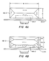
- Shield 4A-3 and 4B-3 of the present invention exposes the transducer 4A-2, 4B-2 to one magnetic domain. If the shield 4A-3 is made from material exhibiting uniaxial anisotropy, due to magnetocrystalline, and/or magnetostriction effects, the material must be cut so that its long axis is parallel to the magnetic easy axis of the material.
- the magnetic easy axis is the axis along which the magnetic field prefers to lie.
- this easy axis must be parallel to the track width of the storage medium 4A-5 and parallel to the long axis of the transducer 4A-2 as shown in Figure 4A.
- the height H of the shield 4A-3 must be more than 4 times height h of the transducer 4A-2.
- the height H of the shields 4B-3 In order to produce a shield with low magnetic reluctance, the height H of the shields 4B-3 must be significantly greater than the characteristic length of flux decay in the transducer 4B-2. If the height of the shield 4B-3 is greater than 10 times the characteristic length of flux decay in the transducer 4B-2, then the shield 4B-3 is essentially infinite in size, has low magnetic reluctance and hence does not limit the readback efficiency of the sensor element 4B-2.
- the length of flux decay in the transducer 4B-2 is where ⁇ is permeability of the sensor; g is the gap length shown in Figure 2, and where t is the thickness of the transducer.
- the height of the shield 4B-3 should be significantly greater, for example, 100 ⁇ m.
- H A is the external magnetic field
- H K is the anisotropic field of the shield material
- M S the saturation magnetization of the shield material
- T the thickness of the shield as shown in Figure 2
- H is the height of the shield as shown in Figure 4B.
- the value of the Stoner-Wolfarth equation should be less than .1.
- the lower limit of the ration T/H is approximately .01.
- the shield height must be less than 200 ⁇ m.
- the shield's ability to resist magnetization can be further augmented by making the shields 4B-3 from materials that provide higher H K and 4 ⁇ M S values.
- concentrations of M and N elements are selected to obtain zero magnetostrictive material, that is, material insensitive to external stress.
Landscapes
- Engineering & Computer Science (AREA)
- Manufacturing & Machinery (AREA)
- Magnetic Heads (AREA)
- Measuring Magnetic Variables (AREA)
Applications Claiming Priority (2)
| Application Number | Priority Date | Filing Date | Title |
|---|---|---|---|
| US91316486A | 1986-09-29 | 1986-09-29 | |
| US913164 | 1986-09-29 |
Publications (2)
| Publication Number | Publication Date |
|---|---|
| EP0262925A2 true EP0262925A2 (de) | 1988-04-06 |
| EP0262925A3 EP0262925A3 (de) | 1989-07-26 |
Family
ID=25432991
Family Applications (1)
| Application Number | Title | Priority Date | Filing Date |
|---|---|---|---|
| EP87308619A Ceased EP0262925A3 (de) | 1986-09-29 | 1987-09-29 | Wandlerabschirmung |
Country Status (2)
| Country | Link |
|---|---|
| EP (1) | EP0262925A3 (de) |
| JP (1) | JP3037335B2 (de) |
Cited By (4)
| Publication number | Priority date | Publication date | Assignee | Title |
|---|---|---|---|---|
| EP0576369A3 (en) * | 1992-06-23 | 1996-02-14 | Eastman Kodak Co | Shielded dual element magnetoresistive reproduce head exhibiting high density signal amplification |
| EP0635822A3 (de) * | 1993-07-20 | 1996-08-07 | Sony Corp | Magnetoresistiver Dünnfilmmagnetkopf. |
| EP0702357A3 (de) * | 1994-09-16 | 1996-11-27 | Toshiba Kk | Magnetowiderstandeffektkopf und Magnetaufzeichnungs-/Wiedergabekopf daraus |
| US6256171B1 (en) | 1996-09-30 | 2001-07-03 | Kabushiki Kaisha Toshiba | Thin film magnetic head having an improved heat dispersion and magnetic recording apparatus using the same |
Family Cites Families (4)
| Publication number | Priority date | Publication date | Assignee | Title |
|---|---|---|---|---|
| US3881190A (en) * | 1973-09-20 | 1975-04-29 | Ibm | Shielded magnetoresistive magnetic transducer and method of manufacture thereof |
| US3975772A (en) * | 1975-06-02 | 1976-08-17 | International Business Machines Corporation | Double shielded magnetorestive sensing element |
| FR2502375B1 (fr) * | 1981-03-20 | 1989-08-18 | Cii Honeywell Bull | Transducteur magnetoresistant de lecture d'informations a tres haute densite |
| JPS5994224A (ja) * | 1982-11-19 | 1984-05-30 | Fujitsu Ltd | 薄膜磁気ヘツドの構造 |
-
1987
- 1987-09-29 EP EP87308619A patent/EP0262925A3/de not_active Ceased
- 1987-09-29 JP JP62247724A patent/JP3037335B2/ja not_active Expired - Lifetime
Cited By (5)
| Publication number | Priority date | Publication date | Assignee | Title |
|---|---|---|---|---|
| EP0576369A3 (en) * | 1992-06-23 | 1996-02-14 | Eastman Kodak Co | Shielded dual element magnetoresistive reproduce head exhibiting high density signal amplification |
| EP0635822A3 (de) * | 1993-07-20 | 1996-08-07 | Sony Corp | Magnetoresistiver Dünnfilmmagnetkopf. |
| EP0702357A3 (de) * | 1994-09-16 | 1996-11-27 | Toshiba Kk | Magnetowiderstandeffektkopf und Magnetaufzeichnungs-/Wiedergabekopf daraus |
| US6369992B1 (en) | 1994-09-16 | 2002-04-09 | Kabushiki Kaisha Toshiba | Yoke-type head with magneto-resistance effect film recessed from medium facing surface and extending across magnetic gap |
| US6256171B1 (en) | 1996-09-30 | 2001-07-03 | Kabushiki Kaisha Toshiba | Thin film magnetic head having an improved heat dispersion and magnetic recording apparatus using the same |
Also Published As
| Publication number | Publication date |
|---|---|
| EP0262925A3 (de) | 1989-07-26 |
| JP3037335B2 (ja) | 2000-04-24 |
| JPS6394413A (ja) | 1988-04-25 |
Similar Documents
| Publication | Publication Date | Title |
|---|---|---|
| US4843506A (en) | Shields of magnetoresistive transducers | |
| KR960025335A (ko) | 자기저항 헤드와 자기저항 헤드에서의 정전하 축적으로 인한 싱글 및 더블 비트 오류를 감소시키는 방법 | |
| EP0628835A2 (de) | Magnetoresistiver Sensor | |
| JPS63117309A (ja) | 磁気抵抗性読取変換器 | |
| JP2002100006A (ja) | 垂直記録ヘッドおよび垂直磁気記録装置 | |
| US6995950B2 (en) | Transverse biased shields for perpendicular recording to reduce stray field sensitivity | |
| US4807074A (en) | Magnetoresistive head for magnetic disk | |
| US4488194A (en) | Magnetoresistant transducer for reading very high-density data | |
| EP0631276A2 (de) | Magnetoresistiver Lesekopf mit einer Austauschschicht | |
| EP0262925A2 (de) | Wandlerabschirmung | |
| JP2533255B2 (ja) | 薄膜磁気ヘッド | |
| JPS63304416A (ja) | 磁気抵抗効果型再生ヘツド | |
| JP2006012250A (ja) | 垂直磁気記録用磁気ヘッド | |
| JPS5919213A (ja) | 垂直磁化記録用ヘツド | |
| JP3209290B2 (ja) | 薄膜磁気ヘッド及び磁気ディスク装置 | |
| US5117320A (en) | Magnetostrictive head with d.c. bias magnetic field | |
| US6154350A (en) | Soft adjacent layer-biased magnetoresistive head and method | |
| JPH0256713A (ja) | 磁気抵抗効果型再生ヘッド | |
| JPS60133517A (ja) | 磁気抵抗効果型磁気ヘツド | |
| JPH0490101A (ja) | 垂直磁気記録装置 | |
| JPH06187615A (ja) | 磁気抵抗効果再生ヘッド | |
| JPS6233303A (ja) | 磁気抵抗型磁気ヘツドの検出方法 | |
| JPH06267036A (ja) | 薄膜磁気ヘッド | |
| JPS62107422A (ja) | 磁気読取装置 | |
| JP2003208706A (ja) | 磁気ヘッド |
Legal Events
| Date | Code | Title | Description |
|---|---|---|---|
| PUAI | Public reference made under article 153(3) epc to a published international application that has entered the european phase |
Free format text: ORIGINAL CODE: 0009012 |
|
| AK | Designated contracting states |
Kind code of ref document: A2 Designated state(s): DE FR GB |
|
| PUAL | Search report despatched |
Free format text: ORIGINAL CODE: 0009013 |
|
| AK | Designated contracting states |
Kind code of ref document: A3 Designated state(s): DE FR GB |
|
| 17P | Request for examination filed |
Effective date: 19891030 |
|
| 17Q | First examination report despatched |
Effective date: 19910411 |
|
| STAA | Information on the status of an ep patent application or granted ep patent |
Free format text: STATUS: THE APPLICATION HAS BEEN REFUSED |
|
| 18R | Application refused |
Effective date: 19920508 |
|
| RIN1 | Information on inventor provided before grant (corrected) |
Inventor name: SIMMONS, RALPH F., JR. Inventor name: GILL, HARDAYAL S. |