EP0262978A2 - Appareil répondeur téléphonique automatique - Google Patents
Appareil répondeur téléphonique automatique Download PDFInfo
- Publication number
- EP0262978A2 EP0262978A2 EP87308737A EP87308737A EP0262978A2 EP 0262978 A2 EP0262978 A2 EP 0262978A2 EP 87308737 A EP87308737 A EP 87308737A EP 87308737 A EP87308737 A EP 87308737A EP 0262978 A2 EP0262978 A2 EP 0262978A2
- Authority
- EP
- European Patent Office
- Prior art keywords
- memory medium
- incoming message
- stored
- auxiliary memory
- main memory
- Prior art date
- Legal status (The legal status is an assumption and is not a legal conclusion. Google has not performed a legal analysis and makes no representation as to the accuracy of the status listed.)
- Granted
Links
Images


Classifications
-
- H—ELECTRICITY
- H04—ELECTRIC COMMUNICATION TECHNIQUE
- H04M—TELEPHONIC COMMUNICATION
- H04M1/00—Substation equipment, e.g. for use by subscribers
- H04M1/64—Automatic arrangements for answering calls; Automatic arrangements for recording messages for absent subscribers; Arrangements for recording conversations
- H04M1/65—Recording arrangements for recording a message from the calling party
- H04M1/6505—Recording arrangements for recording a message from the calling party storing speech in digital form
-
- H—ELECTRICITY
- H04—ELECTRIC COMMUNICATION TECHNIQUE
- H04M—TELEPHONIC COMMUNICATION
- H04M1/00—Substation equipment, e.g. for use by subscribers
- H04M1/64—Automatic arrangements for answering calls; Automatic arrangements for recording messages for absent subscribers; Arrangements for recording conversations
- H04M1/65—Recording arrangements for recording a message from the calling party
- H04M1/6515—Recording arrangements for recording a message from the calling party using magnetic tape
Definitions
- This invention relates to automatic telephone answering apparatus.
- the length of an incoming message is indefinite because of variety of a quantity of business given by a person who communicates, individual variations of manner of speaking or the like. It is desirable that the capacity of the incoming message memory medium is more than ten minutes even at the minimum because of necessity of storing incoming messages of plural times.
- the technique e.g., the current adaptive delta PCM etc.
- data quantity reaches s4 to 3s K bit/sec. Accordingly, for ensuring the capacity of incoming message medium of ten minutes, a semiconductor memory of 14.4 to 19.2 mega bits is required. Such a semiconductor memory cannot be economically realized. For this reason, semiconductor memories presently commercialized only have a capacity of 10 to 45 seconds.
- the invention provides automatic telephone answering apparatus comprising a main memory medium, an auxiliary memory medium, and control means operable, such that, in a recording mode of the apparatus, all or part of an incoming message or messages is/are first stored in said auxiliary memory medium before storing into said main memory medium takes place, and, in a replaying mode of the apparatus, the message(s) or part thereof stored in said auxiliary memory medium is/are first reproduced whilst said main memory medium is being rewound or reset, whereafter said incoming message(s) stored in said main memory medium is/are reproduced.
- Figs. 1 to 3 are explanatory views illustrating, in a block form, different exemplary embodiments of an automatic answering telephone set in accordance with the present invention.
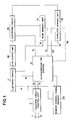
- Fig. 1 is a block diagram showing the principle of an automatic answering telephone in accordance with the invention.
- an indication of a message transmitting unit is omitted.
- reference numerals 1 and 2 denote terminals for connecting a telephone circuit thereto, respectively.
- Reference numeral 3 denotes a telephone circuit control unit, reference numeral 4 a bidirectional voice signal line, reference numeral 5 a calling detection output signal line for the telephone circuit control unit 3, and reference numeral 6 an input signal line for circuit control of the telephone circuit control unit 3.
- Reference numeral 7 denotes an electronic siwtch for effecting switching of storing/reproducing of an incoming message
- reference numeral 8 a signal line for controlling the electronic switch 7
- reference numeral 9 a microcomputer for control
- reference numeral 10 a line output amplifier.
- Reference numeral 11 denotes a control signal line for effecting switching of a reproduced output of a main memory unit 17 and a reproduced output of an auxiliary memory unit 18.
- Reference numeral 12 denotes a control signal bus for control of storing/rewinding/reproducing/starting/stopping/ and the like of the main memory unit 17.
- Reference numeral 13 denotes a control signal bus for the auxiliary memory unit 18, which is similar to the control signal bus for the main memory unit 17.
- Reference numerals 14 and 15 denote memory input signal lines for an incoming message, respectively.
- Reference numeral 16 denotes an electronic circuit for effecting switching of a reproduced output of the auxiliary memory unit 18 and a reproduced output of the main memory unit 17, or for allowing the reproduced outputs of the both memory units 17 and 18 to cross over at the time of reproduction.
- Reference numeral 17 denotes the above-mentioned main memory unit provided with a main memory medium
- reference numeral 18 the above-mentioned auxiliary memory unit provided with an auxiliary memory medium
- reference numeral 19 an address signal bus when a semiconductor memory is used as the auxiliary memory unit 18, and reference numeral 20 a remote control signal decoder.
- the main memory unit 17 employed in the illustrated embodiment uses a magnetic tape of the compact cassette type or the microcassette type, or the like as the nain memory medium.
- This main memory unit 17 is constructed so that all the operations for storing/reproducing, driving/stopping/rewinding of the memory medium, movement of the magnetic head, and the like can be electrically controlled by control signals from the microcomputer 9.
- the auxiliary memory unit 18 employed in the illustrated embodiment constitutes the auxiliary memory medium with a voice analysis/synthesis LSI and a semiconductor memory, or uses a magnetic tape or a magnetic disk of the compact cassette type or the microcassette type, or the endless type in the same manner as in the main memory unit 17.
- This auxiliary memory unit 18 is also constituted so that all the operations for storing/reproducing, driving/stopping/rewinding of the memory medium, movement of the magnetic head, and the like can be electrically controlled by control signals from the microcomputer 9.
- an incoming number discriminator, a counter or an auxiliary memory medium residual or remaining capacity counter which is reset at the time when reproducing an incoming message and listening thereto, or at the time when use of the automatic answering telephone set is initiated, is set in the microcomputer 9.
- the program of the microcomputer 9 in regard to the memory of an incoming message is prepared in advance as follows.
- auxiliary memory medium When the residual or remaining capacity of the auxiliary memory medium is above a predetermined capacity, a first incoming message input from a telephone externally equipped or incoming messages subsequent thereto are first stored into the auxiliary memory medium of the auxiliary memory unit 18. On the other hand, when the residual capacity of the auxiliary memory medium is below the predetermined value, the main memory unit 17 is activated or started to thereby continuously store the subsequent incoming messages into the main memory medium, or to store a message received at first in the auxiliary memory medium when the residual capacity of the auxiliary memory medium exceeds the predetermined capacity to reach the end of the message.
- auxiliary memory medium is constituted with a medium such as a magnetic tape which requires rewinding or an operation similar to rewinding
- the auxiliary memory unit 18 is caused to automatically effect an operation such as rewinding, thus placing it in reproducing/ standby state.
- the program of the microcomputer 9 when reproducing an incoming message and listening thereto is prepared in advance as follows.
- an automatic answering telephone set is subjected to remote control by a telephone externally equipped
- a reproducing instruction and a secret code by a DTMF (Dual Tone Multi Frequency) signal etc. from the telephone externally equipped are sent.
- the microcomputer 9 via the remote control signal decoder 20
- the received code is collated or compared with a secret code stored in advance in the microcomputer 9.
- the operation enters into the reproducing mode.
- the automatic answering telephone set is operated so that it is directly brought into reproducing mode
- the operation also enters into the reproducing mode.
- the incoming message stored in the auxiliary memory unit 18 is first reproduced, thereafter outputting the reproduced output to the telephone circuit via the electronic circuit 16, the line output amplifier 18, the electronic switch 7, and the telephone circuit control unit 3.
- the main memory medium of the main memory unit 17 is rewound, placing it in reproducing standby state.
- the reproduction of the main memory unit 18 is activated or started immediately at that time or after a short time elapses from that time.
- the microcomputer 9 controls the electronic circuit 16, thus activating the main memory unit 17 for the purpose of reproducing the incoming message, and simultaneously outputting a reproduced output of the main memory unit 17 to the line output amplifier 10.
- switching of the reproduction may adopt the following system.
- the predetermined reproduction residual capacity of the auxiliary memory medium is caused to be less than the predetermined storing or memory residual capacity, thus allowing the microcomputer 9 to control the electronic circuit 16.
- the reproduction of the main memory unit 17 is initiated with a signal level reproduced at the auxiliary memory unit 18 being gradually lowering and overlapping with a signal level reproduced at the main memory unit 17, and its reproduced signal level is gradually increased.
- a reproduced signal from the auxiliary memory unit 18 and a reproduced signal from the main memory unit 17 are caused to cross over.
- Fig. 2 is a block diagram showing an embodiment in which a semiconductor memory is used as an auxiliary memory medium in an automatic answering telephone set in accordance with the present invention.
- reference numerals 101 and 102 denote terminals to which a telephone circuit is connected, respectively.
- Reference numeral 103 denotes a telephone circuit control unit, reference numeral 104 a bidirectional voice signal line, and reference numeral 105 an electronic switch for effecting switching of input/output of a voice signal to the telephone circuit.
- Reference numeral 106 denotes an audio band amplifier/ voice switch, which is used commonly to storing of a sending message and an incoming message. This is an electronic circuit to detect whether or not a voice signal having a level above a certain level continues.
- Reference numeral 107 denotes a microphone used for memorizing a sending message.
- Reference numeral 108A denotes a push-button switch depressed at the time of memorizing a sending message
- reference numeral 108B a push-button switch depressed at the time of reproducing an incoming message stored in the automatic answering telephone set in the vicinity thereof and listening to the reproduced incoming message
- reference numeral 108C a push-button switch depressed at the time of selecting an automatic answering mode.
- Reference numeral 109 denotes a band pass filter for limiting an audio band
- reference numeral 110 a line output amplifier
- reference numeral 111 an input/output control signal line
- a reference numeral 112 a calling detection signal line.
- Reference numeral 113 denotes a circuit control signal used when a microcomputer 115 which will be described later instructs the telephone circuit control unit103 to close/open the telephone circuit.
- Reference numeral 114 denotes a control signal bus for connecting the push-button switches 108A to 108C, the audio band amplifier/voice switch 106 for memorization, and the microcomputer 115 to each other.
- Reference numeral 115 denotes the above-mentioned microcomputer, and reference numeral 116 a remote control signal decoder.
- Reference numeral 117 denotes an electronic circuit/ beep tone oscillating circuit (which corresponds to the electronic circuit 16 in Fig. 1). This circuit is used for switching an input from the line output amplifier 110 to a main memory unit 123 or a semiconductor memory 127 provided in the voice memorizing and reproducing circuit 124, or for allowing it to cross over between the both memory units 123 and 127.
- Reference numeral 118 denotes a control signal line through which a control signal for controlling the electronic circuit/beep tone oscillating circuit 117 is sent from the microcomputer 115.
- Reference numeral 119 denotes a control signal bus used for control of storing/reproducing/starting/stopping/ rewinding etc.
- Reference numeral 120 denotes an address signal bus used for informing the microcomputer 115 of residual capacity of the auxiliary memory medium provided in the voice memorizing and reproducing unit 124.
- Reference numeral 121 denotes a decode signal line used for inputting a decoded output from the decoder 116 to the microcomputer 115.
- Reference numeral 122 denotes a control signal bus used for sending a control signal to instruct "starting/stopping of both storing and reproducing of a sending message", “starting/stopping of both storing and reproducing of an incoming message”, and the like from the microcomputer 115 to the voice memorizing and reproducing unit 124.
- Reference numeral 123 denotes the above-mentioned main memory unit for storing an incoming message, which uses a magnetic tape of the compact cassette type or microcassette type as the memory medium.
- This memory unit 123 is constructed so that control of driving/stopping/rewinding/storing/reproducing of the memory medium/movement of the magnetic tape etc. is electrically executed by control signals from the microcomputer 115.
- Reference numeral 124 denotes the above-mentioned voice memorizing and reproducing unit (corresponding to the auxiliary memory unit 18 in Fig. 1). This unit 124 is used commonly to storing/reproducing of a sending message and an auxiliary storing/reproducing of an incoming message.
- Reference numeral 125 denotes a voice analysis/ synthesis LSI
- reference numeral 127 a semiconductor memory (SRAM or DRAM).
- Reference numeral 126 denotes a bidirectional data line/control signal bus/address bus connecting between the voice analysis/synthesis LSI 125 and the semiconductor memory 127.
- Reference numeral 128 denotes a reproduced output signal line for the voice memorizing and reproducing unit 124, reference numeral 129 a voice output amplifier, and reference numeral 130 a speaker.
- the memory of a sending message in the automatic answering telephone set in Fig. 2 is carried out as follows.
- the audio band amplifier/voice switch 106 selects the microphone 107, and at the same time the microcomputer 115 outputs a control signal to the voice memorizing and reproducing unit 124 through the control signal bus 122 so that the voice memorizing and reproducing 124 stores a sending message.
- the sending message is stored into the sending message area of the semiconductor memory 127.
- the voice memorizing and reproducing unit 124 is brought into reproducing state of a sending message.
- a control is carried out by the microcomputer 115 such that a reproduced signal of the sending message is input, without closing telephone circuit, to the voice output amplifier 129 via the reproduced output signal line 128, the electronic circuit/beep tone oscillating circuit 117, the line output amplifier 110, and the electronic switch 105, thereby permitting a user to listen to the sending message by making use of the speaker 30.
- a calling detection signal is input to the microcomputer 115 via the calling detection signal line 112 by the calling detection circuit provided in the telephone circuit control unit 103.
- the microcomputer 115 judges that valid receiption has been effected to output a line closing signal to the calling detection signal line 112, thus allowing the telephone circuit control unit 103 to close the telephone circuit.
- the microcomputer 115 outputs a signal for switching the electronic switch 105 to the reproducing mode and a signal for switching the electronic circuit/beep tone oscillating circuit 117 to the side of the voice memorizing and reproducing unit 124 to the input/output control signal line 111 and the control signal line 118, respectively. Then, the microcomputer 115 allows the voice memorizing and reproducing unit 124 to be in reproducing state of a sending message through the control signal bus 122.
- a sending message stored in advance in the semiconductor memory 127 is output to the telephone circuit connected to the terminals 101 and 102 via the reproduced output signal line 128, the electronic circuit/beep-tone oscillating circuit 117, the line output amplifier 110, the electronic switch 105, and the telephone circuit control unit 103.
- the microcomputer 115 When the microcomputer 115 receives a signal from the address signal bus 120 to recognize the termination of the sending message, it instructs the electronic circuit/beep tone oscillating circuit 117 to output a beep tone through the control signal line 118. Subsequently to the instruction to output beep tone, the microcomputer 115 judges the memory residual information of the incoming message in the semiconductor memory 127 which is held on a RAM incorporated in the microcomputer 115. When the residual capacity is above a predetermined capacity, the microcomputer 115 instructs the voice memorizing and reproducing unit 124 to store the incoming message through the control signal bus 122.
- the microcomputer 115 instructs the main memory unit 123 to store the incoming message through the control signal bus 119.
- the microcomputer 115 monitors addresses of the semiconductor memory 127 through the address signal bus 120. When the residual capacity of the semiconductor memory 127 is below the predetermined capacity, the microcomputer 115 instructs the main memory unit 123 to store the incoming message through the control signal bus 119.
- microcomputer 115 When the microcomputer 115 recognizes that the incoming message is in soundless state for a time more than a predetermined time by the voice switch function added to the audio band amplifier/voice switch 106, memory of the incoming message is completed, thus placing the automatic answering telephone set in calling wait condition.
- the incoming message reproducing mode is started when the push-button switch 108B is depressed, or when the decoder 116 decodes a remote control signal and a secret code after responding to a call from a telephone externally equipped and then a secret code set in advance at the microcomputer 115 is in correspondence with the secret code decoded by the decoder 116.
- the microcomputer 115 When the incoming message reproducing mode is started, the microcomputer 115 first outputs control signals to the input/output control signal line 111 and the control signal line 118 so as to select the reproduced output of the voice memorizing and reproducing unit 124, thereafter to output a control signal to the control signal bus 122 so that the voice memorizing and reproducing unit 124 is in the incoming message reproducing state.
- the reproducing mode is started by remote control
- the reproduced output of the incoming message of the voice memorizing and reproducing unit 124 is output to the telephone circuit connected to the terminals 101 and 102 via the reproduced output signal line 128, the electronic circuit/beep tone oscillating circuit 117, the line output amplifier 110, the electronic switch 105, and the telephone circuit control unit 103.
- a control is effected by the microcomputer 115 such that the telephone circuit control unit 103 does not close the telephone circuit and the reproduced output of the voice memorizing and reproducing unit 124 is output to the speaker 130 via the reproduced output signal line 128, the electronic circuit/beep tone oscillating circuit 117, the line output amplifier 110, the electronic switch 105, and the voice output amplifier 129.
- the microcomputer 115 Immediately when the voice memorizing and reproducing unit 124 initiates the reproduction of the incoming message, the microcomputer 115 outputs a control signal to the bus 119 so that the incoming message memory wait condition of the main memory unit 123 is released and the memory medium of the main memory unit 123 is rewound, resulting in reproducing wait condition.
- the microcomputer 115 monitors addresses at which the semiconductor memory 127 is accessed to start reproduction of the main memory unit 123 when the residual capacity of the incoming message memory medium is below a predetermined capacity.
- the electronic circuit/beep tone oscillating circuit 117 is controlled by the microcomputer 115 so that it switches the incoming message reproduced signal input to the line output amplifier 110 from the voice memorizing and reproducing unit 124 to the main memory unit 123, or it gradually increases the level of the reproduced signal from the main memory unit 123 while gradually reducing the level of the reproduced signal from the voice memorizing and reproducing unit 124, thus allowing the reproduced signals from the both memory units to cross over.
- the microcomputer 115 executes all processings required for returning to the automatic answering mode.
- Fig. 3 shows a further embodiment of an automatic answering telephone set in accordance with the invention wherein a magnetic tape is used instead of the semiconductor memory as the auxiliary memory medium.
- a new cassette tape etc. may be independently provided as the auxiliary memory medium, but it is possible to commonly use the cassette tape for storing a sending message for this purpose.
- Fig. 3 shows the example of such a common use and is a block diagram mainly illustrating the auxiliary memory unit of the automatic answering telephone set.
- reference numeral s01 denotes a magnetic tape of the endless type in which a sensing metal leaf is attached to the joining portion
- reference numeral 202 a sensing post
- reference numeral 203 an erasing magnetic head
- reference numeral 204 a memorizing and reproducing magnetic head
- reference numeral 205 a direct drive type electric motor and a capstan
- reference numeral 206 an electronic switch for starting and stopping the electric motor 205.
- Reference numeral 207 denotes a pinch roller for pressing the tape onto the capstan 205
- reference numeral 208 a pulse generator which generates a pulse corresponding to the rotation of the pinch roller 207 in order to input addresses of the memory medium to the microcomputer.
- Reference numeral 209 denotes an electronic switch which effects on/off of an erasing current caused to flow in the erasing head, reference numeral 210 an electronic switch for effecting switching of storing and reproducing, reference numeral 211 an input terminal for a voice signal for memory, and reference numeral 212 an amplifier for allowing a memory current to flow in the memorizing/reproducing magnetic head 204.
- Reference numeral 213 denotes an equivalent amplifier (equalizer) for a signal reproduced by memorizing/reproducing magnetic head 204, reference numeral 214 an output terminal for a reproduced signal, reference numeral 215 a dc power source, reference numeral 216 an output terminal for a signal informing to the microcomputer of zero-th address of the memory medium, reference numeral 217 an output terminal of the pulse generator s08, reference numeral 218 a terminal for a signal which controls the electronic switch 206 provided for control of drive and stop of the memory medium, and reference numeral 219 a terminal for a signal which controls memorizing and reproducing operation.
- an equivalent amplifier equalizer
- the output terminals 216, 217 and 219 in Fig. 3 are indicated collectively as the control signal bus 122 in Fig. 2.
- the terminal 218 in Fig. 3 corresponds to the address signal bus 120 in Fig. 2.
- a tape having a memory capacity of about one to two minutes in terms of time is used for the magnetic tape 201.
- a portion corresponding to about 15 to 30 seconds from the sensing leaf (zero-th address) of the tape 201 is assigned to the sending message area, and the remaining portion is used as an auxiliary memory area for storing an incoming message.
- a control is effected by the microcomputer such that at the calling wait time in the automatic answering mode, the zero-th address of the magnetic tape 201 is always stopped at the position of the memorizing and reproducing magnetic head 204.
- the automatic answering telephone set in the third embodiment can provide a function equivalent to the function in the second embodiment.
- a control capable of fast-feeding the sending message portion or the remaining portion thereof may be conducted.
- the telephone set is devised so that an incoming message stored in the auxiliary memory medium is first reproduced and the main memory medium is rewound during such a reproducing operation, and then an incoming message stored in the main memory medium is reproduced, when reproducing the incoming message and listening thereto, it is possible to instantaneously listen to the incoming message without requiring a wasteful wait time. For this reason, a user does not feel irritated and telephone charge can be saved when reproducing the incoming message using a telephone by remote control.
- auxiliary memory medium Since the contents of the auxiliary memory medium can be reproduced subsequently to the sending message or instantaneously as long as at least one incoming message is stored in the auxiliary memory medium, even if incoming messages stored are many or less, a user can instantaneously listen to a desired incoming message without requiring a wasteful wait time.
- this automatic answering telephone set Since an incoming message stored in the main memory medium is automatically reproduced without interruption subsequently to the reproduction of the incoming message stored in the auxiliary memory medium, this automatic answering telephone set is convenient in that no switching operation etc. is required.
Landscapes
- Engineering & Computer Science (AREA)
- Signal Processing (AREA)
- Telephone Function (AREA)
- Telephonic Communication Services (AREA)
- Mobile Radio Communication Systems (AREA)
Applications Claiming Priority (2)
| Application Number | Priority Date | Filing Date | Title |
|---|---|---|---|
| JP234002/86 | 1986-10-01 | ||
| JP23400286 | 1986-10-01 |
Publications (3)
| Publication Number | Publication Date |
|---|---|
| EP0262978A2 true EP0262978A2 (fr) | 1988-04-06 |
| EP0262978A3 EP0262978A3 (en) | 1989-05-10 |
| EP0262978B1 EP0262978B1 (fr) | 1993-03-03 |
Family
ID=16964015
Family Applications (1)
| Application Number | Title | Priority Date | Filing Date |
|---|---|---|---|
| EP87308737A Expired - Lifetime EP0262978B1 (fr) | 1986-10-01 | 1987-10-01 | Appareil répondeur téléphonique automatique |
Country Status (4)
| Country | Link |
|---|---|
| US (1) | US4885764A (fr) |
| EP (1) | EP0262978B1 (fr) |
| JP (1) | JPS63226160A (fr) |
| DE (1) | DE3784429D1 (fr) |
Cited By (4)
| Publication number | Priority date | Publication date | Assignee | Title |
|---|---|---|---|---|
| GB2211378A (en) * | 1987-10-19 | 1989-06-28 | American Telephone & Telegraph | Announcement storage system for telephone answering machines |
| EP0440017A1 (fr) * | 1990-01-30 | 1991-08-07 | Rolf Dr. Wilhelms | Arrangement de réception et d'enregistrement d'image et/ou de son |
| EP0399759A3 (fr) * | 1989-05-24 | 1992-09-09 | Sony Corporation | Un repondeur téléphonique automatique |
| DE19963630A1 (de) * | 1999-12-29 | 2001-07-12 | Atanas Salabaschew | Rückwirkende Gesprächsaufzeichnung |
Families Citing this family (4)
| Publication number | Priority date | Publication date | Assignee | Title |
|---|---|---|---|---|
| US4991199A (en) * | 1988-05-05 | 1991-02-05 | Transaction Technology, Inc. | Computer and telephone apparatus with user friendly computer interface and enhanced integrity features |
| JP2762564B2 (ja) * | 1989-05-24 | 1998-06-04 | ソニー株式会社 | 留守番電話装置 |
| US5870724A (en) | 1989-12-08 | 1999-02-09 | Online Resources & Communications Corporation | Targeting advertising in a home retail banking delivery service |
| DE19709973A1 (de) * | 1997-03-11 | 1998-09-24 | Siemens Ag | Digitaler Anrufbeantworter |
Family Cites Families (8)
| Publication number | Priority date | Publication date | Assignee | Title |
|---|---|---|---|---|
| JPS5230085B2 (fr) * | 1972-06-07 | 1977-08-05 | ||
| JPS531124B2 (fr) * | 1973-12-17 | 1978-01-14 | ||
| JPS535168B2 (fr) * | 1974-02-19 | 1978-02-24 | ||
| JPS5158006A (ja) * | 1974-11-18 | 1976-05-21 | Aiwa Co | Rusubandenwasochi |
| US4319089A (en) * | 1978-11-03 | 1982-03-09 | Quasar Microsystems, Inc. | Telephone answering machine |
| DE2854516B1 (de) * | 1978-12-16 | 1980-03-20 | Deutsche Fernsprecher Gmbh | Fernsprechapparat mit Anrufbeantworter |
| US4573140A (en) * | 1983-03-30 | 1986-02-25 | Voicetek Corporation | Method of and apparatus for voice communication storage and forwarding with simultaneous access to multiple users |
| US4588857A (en) * | 1983-10-05 | 1986-05-13 | Arsem A Donald | Message aggregating dictation system |
-
1987
- 1987-09-25 US US07/101,080 patent/US4885764A/en not_active Expired - Fee Related
- 1987-09-28 JP JP62243044A patent/JPS63226160A/ja active Granted
- 1987-10-01 EP EP87308737A patent/EP0262978B1/fr not_active Expired - Lifetime
- 1987-10-01 DE DE8787308737T patent/DE3784429D1/de not_active Expired - Lifetime
Cited By (5)
| Publication number | Priority date | Publication date | Assignee | Title |
|---|---|---|---|---|
| GB2211378A (en) * | 1987-10-19 | 1989-06-28 | American Telephone & Telegraph | Announcement storage system for telephone answering machines |
| GB2211378B (en) * | 1987-10-19 | 1992-01-29 | American Telephone & Telegraph | Improvements in or relating to telephone answering machines |
| EP0399759A3 (fr) * | 1989-05-24 | 1992-09-09 | Sony Corporation | Un repondeur téléphonique automatique |
| EP0440017A1 (fr) * | 1990-01-30 | 1991-08-07 | Rolf Dr. Wilhelms | Arrangement de réception et d'enregistrement d'image et/ou de son |
| DE19963630A1 (de) * | 1999-12-29 | 2001-07-12 | Atanas Salabaschew | Rückwirkende Gesprächsaufzeichnung |
Also Published As
| Publication number | Publication date |
|---|---|
| DE3784429D1 (de) | 1993-04-08 |
| JPH059981B2 (fr) | 1993-02-08 |
| US4885764A (en) | 1989-12-05 |
| EP0262978B1 (fr) | 1993-03-03 |
| EP0262978A3 (en) | 1989-05-10 |
| JPS63226160A (ja) | 1988-09-20 |
Similar Documents
| Publication | Publication Date | Title |
|---|---|---|
| EP0262978B1 (fr) | Appareil répondeur téléphonique automatique | |
| KR930001824B1 (ko) | 부재시 전화장치 | |
| JPH0449823B2 (fr) | ||
| US5187734A (en) | Telephone message recording device | |
| JPH0422386B2 (fr) | ||
| US4734929A (en) | Telephone answering machines for collect call | |
| JPS5834664A (ja) | 電話装置 | |
| JPH0244428B2 (fr) | ||
| JPS583358A (ja) | 動作状況を音声で明示する留守番電話装置 | |
| JP2935061B2 (ja) | 留守番電話装置 | |
| JP3016357B2 (ja) | 音声記録機能付電話機 | |
| JPS61113347A (ja) | 留守番電話装置に於るメツセ−ジの再生装置 | |
| JPH0434342B2 (fr) | ||
| JPH02119491A (ja) | 留守番テレビ電話 | |
| JPS61157141A (ja) | 留守番電話装置 | |
| JPH0261186B2 (fr) | ||
| JPS6089158A (ja) | 留守番電話装置のモ−ドチエツク方式 | |
| JPS60246160A (ja) | 音声分析合成方式の自動応答装置 | |
| JPS60232754A (ja) | 留守番電話装置 | |
| JPH1023141A (ja) | 留守番電話機 | |
| JPH01189265A (ja) | 留守番電話装置 | |
| JPS6323702B2 (fr) | ||
| JPS63245164A (ja) | 留守番電話機 | |
| JPS60246158A (ja) | 音声分析合成方式の自動応答装置 | |
| JPH0331303B2 (fr) |
Legal Events
| Date | Code | Title | Description |
|---|---|---|---|
| PUAI | Public reference made under article 153(3) epc to a published international application that has entered the european phase |
Free format text: ORIGINAL CODE: 0009012 |
|
| AK | Designated contracting states |
Kind code of ref document: A2 Designated state(s): DE FR GB IT NL |
|
| PUAL | Search report despatched |
Free format text: ORIGINAL CODE: 0009013 |
|
| AK | Designated contracting states |
Kind code of ref document: A3 Designated state(s): DE FR GB IT NL |
|
| RAP1 | Party data changed (applicant data changed or rights of an application transferred) |
Owner name: MIWA, HIROHIDE Owner name: TOKYO KOSUMOSU DENKI KABUSHIKI KAISHA |
|
| 17P | Request for examination filed |
Effective date: 19891006 |
|
| 17Q | First examination report despatched |
Effective date: 19910819 |
|
| GRAA | (expected) grant |
Free format text: ORIGINAL CODE: 0009210 |
|
| AK | Designated contracting states |
Kind code of ref document: B1 Designated state(s): DE FR GB IT NL |
|
| PG25 | Lapsed in a contracting state [announced via postgrant information from national office to epo] |
Ref country code: NL Effective date: 19930303 Ref country code: FR Effective date: 19930303 Ref country code: IT Free format text: LAPSE BECAUSE OF FAILURE TO SUBMIT A TRANSLATION OF THE DESCRIPTION OR TO PAY THE FEE WITHIN THE PRE;WARNING: LAPSES OF ITALIAN PATENTS WITH EFFECTIVE DATE BEFORE 2007 MAY HAVE OCCURRED AT ANY TIME BEFORE 2007. THE CORRECT EFFECTIVE DATE MAY BE DIFFERENT FROM THE ONE RECORDED.SCRIBED TIME-LIMIT Effective date: 19930303 Ref country code: DE Effective date: 19930303 |
|
| REF | Corresponds to: |
Ref document number: 3784429 Country of ref document: DE Date of ref document: 19930408 |
|
| EN | Fr: translation not filed | ||
| NLV1 | Nl: lapsed or annulled due to failure to fulfill the requirements of art. 29p and 29m of the patents act | ||
| PLBE | No opposition filed within time limit |
Free format text: ORIGINAL CODE: 0009261 |
|
| STAA | Information on the status of an ep patent application or granted ep patent |
Free format text: STATUS: NO OPPOSITION FILED WITHIN TIME LIMIT |
|
| 26N | No opposition filed | ||
| PGFP | Annual fee paid to national office [announced via postgrant information from national office to epo] |
Ref country code: GB Payment date: 19950831 Year of fee payment: 9 |
|
| PG25 | Lapsed in a contracting state [announced via postgrant information from national office to epo] |
Ref country code: GB Effective date: 19961001 |
|
| GBPC | Gb: european patent ceased through non-payment of renewal fee |
Effective date: 19961001 |