EP0262982A1 - Stabilisateur d'échelle - Google Patents
Stabilisateur d'échelle Download PDFInfo
- Publication number
- EP0262982A1 EP0262982A1 EP19870308766 EP87308766A EP0262982A1 EP 0262982 A1 EP0262982 A1 EP 0262982A1 EP 19870308766 EP19870308766 EP 19870308766 EP 87308766 A EP87308766 A EP 87308766A EP 0262982 A1 EP0262982 A1 EP 0262982A1
- Authority
- EP
- European Patent Office
- Prior art keywords
- ladder
- stile
- attachment portion
- projections
- pin
- Prior art date
- Legal status (The legal status is an assumption and is not a legal conclusion. Google has not performed a legal analysis and makes no representation as to the accuracy of the status listed.)
- Granted
Links
- 239000003381 stabilizer Substances 0.000 title claims abstract description 22
- 239000000463 material Substances 0.000 claims description 5
- 229910052751 metal Inorganic materials 0.000 description 4
- 239000002184 metal Substances 0.000 description 4
- 239000004677 Nylon Substances 0.000 description 2
- 238000004512 die casting Methods 0.000 description 2
- -1 for example Substances 0.000 description 2
- 239000011521 glass Substances 0.000 description 2
- 238000004519 manufacturing process Methods 0.000 description 2
- 239000002991 molded plastic Substances 0.000 description 2
- 229920001778 nylon Polymers 0.000 description 2
- 230000003019 stabilising effect Effects 0.000 description 2
- 229910000838 Al alloy Inorganic materials 0.000 description 1
- 229910000851 Alloy steel Inorganic materials 0.000 description 1
- AFCARXCZXQIEQB-UHFFFAOYSA-N N-[3-oxo-3-(2,4,6,7-tetrahydrotriazolo[4,5-c]pyridin-5-yl)propyl]-2-[[3-(trifluoromethoxy)phenyl]methylamino]pyrimidine-5-carboxamide Chemical compound O=C(CCNC(=O)C=1C=NC(=NC=1)NCC1=CC(=CC=C1)OC(F)(F)F)N1CC2=C(CC1)NN=N2 AFCARXCZXQIEQB-UHFFFAOYSA-N 0.000 description 1
- 239000002131 composite material Substances 0.000 description 1
- 230000000694 effects Effects 0.000 description 1
- 238000003780 insertion Methods 0.000 description 1
- 230000037431 insertion Effects 0.000 description 1
- 238000012986 modification Methods 0.000 description 1
- 230000004048 modification Effects 0.000 description 1
- 238000004806 packaging method and process Methods 0.000 description 1
- 239000004033 plastic Substances 0.000 description 1
- 229920003023 plastic Polymers 0.000 description 1
- 230000003014 reinforcing effect Effects 0.000 description 1
- 239000007787 solid Substances 0.000 description 1
- 239000010959 steel Substances 0.000 description 1
Images



Classifications
-
- E—FIXED CONSTRUCTIONS
- E06—DOORS, WINDOWS, SHUTTERS, OR ROLLER BLINDS IN GENERAL; LADDERS
- E06C—LADDERS
- E06C7/00—Component parts, supporting parts, or accessories
- E06C7/42—Ladder feet; Supports therefor
-
- E—FIXED CONSTRUCTIONS
- E06—DOORS, WINDOWS, SHUTTERS, OR ROLLER BLINDS IN GENERAL; LADDERS
- E06C—LADDERS
- E06C7/00—Component parts, supporting parts, or accessories
- E06C7/42—Ladder feet; Supports therefor
- E06C7/423—Ladder stabilising struts
-
- E—FIXED CONSTRUCTIONS
- E06—DOORS, WINDOWS, SHUTTERS, OR ROLLER BLINDS IN GENERAL; LADDERS
- E06C—LADDERS
- E06C7/00—Component parts, supporting parts, or accessories
- E06C7/42—Ladder feet; Supports therefor
- E06C7/46—Non-skid equipment
Definitions
- the present invention relates to an accessory for a ladder. More particularly it relates to a device for stabilising a ladder thereby improving the safety of the ladder user.
- the prior device cannot be safely used on ladders with the ends of the rungs or other protrusions projecting from the outer side faces of the stiles. Such protrusions would restrict the available fitting positions of the device up and down the stile if the bracket fitted relatively closely to the stile or would allow unacceptable sideways movement if the bracket was sufficiently loose to allow it to pass over the protrusions.
- the rod connecting the lower ends of the two leg parts makes the device unwieldy and prevents the positioning of the legs at different levels, as may be desirable, for example, on very uneven ground or where one ladder stabiliser has to be placed at a higher level, such as on a step.
- a stabiliser device for attachment to a ladder, comprising an attachment portion adapted to be attached to a stile of a ladder and a leg portion connected to and extending away from the attachment portion, the attachment portion being provided with two projections of adjustable length extending outwardly therefrom and positioned such that the stile can pass freely therebetween when the axis of the stile, the projections, and a line joining the projections are generally mutually perpendicular, and such that the projections engage the respective edge faces of the stile when the device is rotated about an axis generally parallel to the rungs of the ladder.
- the 'sides' of a ladder are the directions to the left and right of a user standing on the ladder, so the side faces of the stiles are the faces normally intersected by the axes of the rungs.
- the front and rear of the ladder are the portions facing towards and away from the user respectively and the edge faces of the stiles are thus the front and rear faces of the stiles, which are generally perpendicular to the side faces.
- the invention is not limited to use with ladders having stiles of a rectangular cross-section: it may be used with virtually any cross-section including rounded sections in which the edge faces will be reduced to vertical lines along the stiles facing towards and away from the user.
- the attachment and leg portions may be constructed of metal such as, for example, steel or aluminium alloy, or of moulded plastics or of composite materials, and preferably are an integral metal die casting.
- the projections may also be of metal or plastics material and are preferably of glass-filled nylon.
- the device is an anchor for attachment to a ladder stile near the bottom of the ladder and operates such that forces on the ladder in use cause an increase in the force of engagement of the projections with the respective edge faces.
- the device is a ladder stay adapted to be attached to a ladder stile near the top of the ladder for holding the top of the ladder away from the wall. Again the force of the ladder on the device and the reaction of the wall on the device cause an increasing engagement between the projections and the edge faces of the stile.
- the projections may take the form of short pieces of rod axially adjustably connected at one end to the attachment portion. They may have extensions at their opposite end, in a direction generally perpendicular to their longitudinal axis, to define a retaining means which can engage the inner side face of the stile to prevent the device from becoming detached during use.
- the adjustable projections allow the device to be attached to a ladder stile sufficiently firmly to provide safe support for the ladder, but the attachment does not prevent the device from sliding down the stile until the device firmly engages both the ground and the edge faces of the ladder stile.
- the retaining means are preferably sufficiently short to allow the device to pass up and down the stile without engaging the rungs for adjustment purposes immediately prior to the use of the attachment and to locate and adjust itself correctly upon contact of the leg portion with the ground.
- at least one of the retaining means is preferably of such a length as to engage one of the rungs of the ladder to prevent the device from sliding down the ladder stile.
- Each projection may be adjustably connected to the attachment portio n by screwing one end thereof into a threaded hole in the attachment portion.
- each projection comprises a pin which can be slidably fitted into a corresponding receiving hole in the attachment portion and clamped into position by any suitable fastening means.
- Such pins may be provided at one end with an eccentric head. Rotation of two such pins about their longitudinal axes within their respective receiving holes provides an adjustable retaining means, since cooperative rotation of said pins effectively alters the distance between the edges of the pin heads.
- the stabiliser device At their maximum spacing the stabiliser device can be positioned onto the ladder stile without securely retaining it. The pins are then rotated to minimise the distance between the pin head edges and clamped into position thereby securely retaining the ladder stile between the two pins, the two pin heads and the attachment portion.
- the inner face of the attachment portion which engages the outer side face of the ladder stile may be further provided with a relieved channel running generally transversely to a line joining the two projections.
- the recessed channel has a hollow dome region generally central to its longitudinal axis.
- the inner face of the attachment portion between and immediately adjacent to the two projections would lie in parallel contact with the outer side face of the ladder stile when the device is in use whilst the recessed channel may pass freely over any protrusions projecting from the approximate midline of the stile face.
- the central region of the inner face of the attachment portion may be the base of a generally hollow dome. The absence of material at this central region further aids in avoiding projections.
- the leg portion connected to the attachment portion is preferably directed slightly outwardly in use so that the area enclosed by the four points of ground contact, i.e. the two ladder anchor feet and the two ladder stiles, is large, thus improving stability by increasing the moment required to tilt the ladder sideways.
- the leg portion may be of uniform cross-section or may taper to provide a point to embed in soft ground or may provide a wider contact area with the ground if it is preferred that the leg should rest on the surface of the ground.
- Any known kind of ladder foot may be attached to the leg, such as friction or suction pads or an articulated foot.
- the two ladder stabilisers for attachment to the respective stiles of a ladder are preferably mirror images of each other.
- Stabilisers 1 and 2 are intended to be used in pairs as shown in Figure 1.
- Each pair comprises a left-hand stabiliser 1 for attachment to the left-hand ladder stile 3 and its mirror image comprising the right-hand stabiliser 2.
- Each stabiliser comprises an attachment portion 5 and a leg portion 4.
- the leg portion 4 of each stabiliser extends outwardly from the attachment portion 5 such that the distance between the two points of contact of the stabiliser legs with the ground is greater than the distance between the ladder stiles. This enhances the stabilising effect.
- Each attachment portion is provided with two projections 6 which engage the opposite edge faces 10, 11 of the ladder stile when the device is attached thereto.
- the attachment portion 5 and leg 4 are formed as an integral metal die casting whilst the projections 6 are of moulded plastics material such as, for example, glass-filled nylon.
- Figures 2 and 3 illustrate how the left-hand adjustable ladder stabiliser is attached to the ladder stile.
- the two projections 6 comprise pins with cylindrical shafts 7 which fit slidably and rotatably into corresponding holes 17 within the attachment portion 5.
- the pins may be of solid design or may be hollow optionally with, for example, a number of interior reinforcing ribs extending radially from a central core for improved strength.
- Each pin is provided at one end with a D-shaped flattened head 9 which may be an integral part of the pin or separately manufactured and fastened to the pin shaft by any conventional means.
- the pins are rotated about their longitudinal axis such that the distance between the pin head edges is maximised and the stabiliser is initially positioned against the outer side face of the ladder stile as shown in Figure s. The pins are then rotated further so that the D-shaped heads partially enclose the ladder stile as shown in Figure 3.
- the pins are also adjustable along their longitudinal axis by a sliding motion guided within holes 17.
- the effective length of the pin shaft protruding from the attachment head can be adjusted to be slightly longer, for example 1-2 mm longer, than the width of the stile edge 10, and the heads may be turned to enclose the stile, before the pins are clamped into position.
- the device is thereby securely attached to the ladder but remains sufficiently loose to slide freely on the stile so that it can adjust itself on contact with the ground whereupon the device is rotated slightly about an axis generally parallel to the rungs of the ladder, i.e. the leg is moved in the direction of the arrow A.
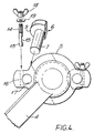
- FIG. 4 shows more clearly the attachment portion of a preferred embodiment of the invention.
- the preferred clamping mechanism comprises a pad bolt 13 having a threaded region at one end 14 and a cut-away radius 15 of a diameter corresponding to the diameter of the pin shaft 7.
- the pad bolt 13 fits into a blind cylindrical bore 16 in the attachment portion 5 and the pin shaft 7 is then fitted into the perpendicular cylindrical receiving hole 17.
- the pin is clamped into position by screwing a wing nut 18 and washer 19 onto the threaded region of the pad bolt which pulls the pad bolt in a direction generally perpendicular to the longitudinal axis of the pin and fastens the pad bolt in position.
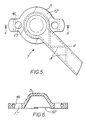
- Figures 5, 6 and 7 show a right-hand stabiliser in greater detail.
- Figure 8 shows a rubber foot 20 which connects to a suitably dovetail- and wedge-shaped plate 21 fixed to the lower end of leg 4.
- the clamping mechanism When it is desired to detach the device the clamping mechanism may be released to allow the pin heads to turn thereby releasing the ladder stile. It is unnecessary to release the device each time the ladder is moved: the device may remain attached to the ladder stile and simply readjusts itself when the ladder is repositioned.
- the adjustability of the device provides for simple fitting of a standard design of stabiliser to almost any size or shape of ladder. With many ladders the device may be manoeuvred to remove it from the ladder without releasing the clamping mechanism: if the leg 4 is moved relative to the ladder stile in a direction opposite to the arrow A in Fig. 3 until a line joining the pins is perpendicular to the axis of the stile, it may be possible to remove the device. This means that once the pins have been clamped in a suitable operative position for a particular ladder they need not be readjusted.
- the leg portion may be tapered towards its free end if it is desired to fix it into soft ground.
- the leg portion may be thickened at its free end to provide a flat or serrated portion or pad, or an articulated foot could be provided.
Landscapes
- Engineering & Computer Science (AREA)
- Mechanical Engineering (AREA)
- Ladders (AREA)
Priority Applications (1)
| Application Number | Priority Date | Filing Date | Title |
|---|---|---|---|
| AT87308766T ATE75520T1 (de) | 1986-10-02 | 1987-10-02 | Stabilisierung fuer leiter. |
Applications Claiming Priority (4)
| Application Number | Priority Date | Filing Date | Title |
|---|---|---|---|
| GB8623702 | 1986-10-02 | ||
| GB868623702A GB8623702D0 (en) | 1986-10-02 | 1986-10-02 | Ladder stabiliser |
| GB8711898A GB2195693B (en) | 1986-10-02 | 1987-05-20 | Ladder stabiliser |
| GB8711898 | 1987-05-20 |
Publications (2)
| Publication Number | Publication Date |
|---|---|
| EP0262982A1 true EP0262982A1 (fr) | 1988-04-06 |
| EP0262982B1 EP0262982B1 (fr) | 1992-04-29 |
Family
ID=26291367
Family Applications (1)
| Application Number | Title | Priority Date | Filing Date |
|---|---|---|---|
| EP19870308766 Expired EP0262982B1 (fr) | 1986-10-02 | 1987-10-02 | Stabilisateur d'échelle |
Country Status (8)
| Country | Link |
|---|---|
| EP (1) | EP0262982B1 (fr) |
| JP (1) | JPS6490388A (fr) |
| AU (1) | AU602727B2 (fr) |
| CA (1) | CA1297850C (fr) |
| DE (1) | DE3778628D1 (fr) |
| ES (1) | ES2030731T3 (fr) |
| IE (1) | IE61323B1 (fr) |
| NZ (1) | NZ222005A (fr) |
Families Citing this family (1)
| Publication number | Priority date | Publication date | Assignee | Title |
|---|---|---|---|---|
| ES2297961B1 (es) | 2004-11-12 | 2009-07-20 | Escaleras Escalibur,S.L. | Accesorios estabilizadores de escaleras portatiles. |
Citations (4)
| Publication number | Priority date | Publication date | Assignee | Title |
|---|---|---|---|---|
| DE255597C (fr) * | ||||
| GB190914108A (en) * | 1909-06-16 | 1910-02-17 | Luke Kenny | Improvements in or connected with Ladders. |
| FR1024706A (fr) * | 1950-09-19 | 1953-04-07 | Dispositif de sécurité applicable notamment aux échelles pour les empêcher de glisser | |
| GB2166793A (en) * | 1984-11-10 | 1986-05-14 | Ian Simpson | Stabilizing means for ladders |
Family Cites Families (1)
| Publication number | Priority date | Publication date | Assignee | Title |
|---|---|---|---|---|
| US4194592A (en) * | 1978-02-23 | 1980-03-25 | Evans Lewis L | Ladder stand-off |
-
1987
- 1987-09-30 CA CA000548202A patent/CA1297850C/fr not_active Expired - Lifetime
- 1987-09-30 NZ NZ22200587A patent/NZ222005A/en unknown
- 1987-10-01 IE IE263487A patent/IE61323B1/en not_active IP Right Cessation
- 1987-10-02 DE DE8787308766T patent/DE3778628D1/de not_active Expired - Lifetime
- 1987-10-02 EP EP19870308766 patent/EP0262982B1/fr not_active Expired
- 1987-10-02 JP JP24963887A patent/JPS6490388A/ja active Pending
- 1987-10-02 ES ES87308766T patent/ES2030731T3/es not_active Expired - Lifetime
- 1987-10-02 AU AU79326/87A patent/AU602727B2/en not_active Ceased
Patent Citations (4)
| Publication number | Priority date | Publication date | Assignee | Title |
|---|---|---|---|---|
| DE255597C (fr) * | ||||
| GB190914108A (en) * | 1909-06-16 | 1910-02-17 | Luke Kenny | Improvements in or connected with Ladders. |
| FR1024706A (fr) * | 1950-09-19 | 1953-04-07 | Dispositif de sécurité applicable notamment aux échelles pour les empêcher de glisser | |
| GB2166793A (en) * | 1984-11-10 | 1986-05-14 | Ian Simpson | Stabilizing means for ladders |
Also Published As
| Publication number | Publication date |
|---|---|
| AU7932687A (en) | 1988-04-14 |
| IE61323B1 (en) | 1994-11-02 |
| NZ222005A (en) | 1991-07-26 |
| DE3778628D1 (de) | 1992-06-04 |
| EP0262982B1 (fr) | 1992-04-29 |
| JPS6490388A (en) | 1989-04-06 |
| AU602727B2 (en) | 1990-10-25 |
| IE872634L (en) | 1988-04-02 |
| CA1297850C (fr) | 1992-03-24 |
| ES2030731T3 (es) | 1992-11-16 |
Similar Documents
| Publication | Publication Date | Title |
|---|---|---|
| US5941343A (en) | Ladder safety accessory | |
| US4798263A (en) | Ladder stabilizer | |
| US10760338B2 (en) | Ladder securing apparatuses, ladders incorporating same and related methods | |
| US4941547A (en) | Safety featured ladder scaffolding | |
| US5156233A (en) | Safety anchor for use with slotted beams | |
| US6966406B2 (en) | Step platform attachable to a ladder | |
| US6729441B1 (en) | Extension ladder safety adapter | |
| US4586586A (en) | Work-step for extension ladder | |
| US5918698A (en) | Safety support apparatus for ladders | |
| US20150218884A1 (en) | Stabilising leg assembly for a ladder | |
| US20070289812A1 (en) | Systems for stabilizing ladders | |
| US20050067224A1 (en) | Safety support for ladders | |
| US4896745A (en) | Adjustable base for ladders and like objects | |
| EP0262982B1 (fr) | Stabilisateur d'échelle | |
| US4730697A (en) | Seat device for a ladder | |
| US3406785A (en) | Ladder supporting surface compensating means | |
| US4130181A (en) | Ladder support system | |
| CA2268612C (fr) | Accessoires d'echelle | |
| US20040140155A1 (en) | Ladder safety attachment | |
| GB2081793A (en) | Improvements in or Relating to Ladders | |
| GB2330612A (en) | Ladder stabiliser | |
| GB2362181A (en) | Ladder step with clamp | |
| WO2008023192A1 (fr) | Stabilisateur d'échelle | |
| GB2055943A (en) | Ladder-levelling device | |
| GB2250312A (en) | A stabiliser device for a ladder |
Legal Events
| Date | Code | Title | Description |
|---|---|---|---|
| PUAI | Public reference made under article 153(3) epc to a published international application that has entered the european phase |
Free format text: ORIGINAL CODE: 0009012 |
|
| AK | Designated contracting states |
Kind code of ref document: A1 Designated state(s): AT BE CH DE ES FR GR IT LI LU NL SE |
|
| 17P | Request for examination filed |
Effective date: 19880916 |
|
| 17Q | First examination report despatched |
Effective date: 19900110 |
|
| 111L | Licence recorded |
Free format text: 0100 ABRU ALUMINIUM LIMITED |
|
| RAP3 | Party data changed (applicant data changed or rights of an application transferred) |
Owner name: STABILAD LIMITED |
|
| GRAA | (expected) grant |
Free format text: ORIGINAL CODE: 0009210 |
|
| AK | Designated contracting states |
Kind code of ref document: B1 Designated state(s): AT BE CH DE ES FR GR IT LI LU NL SE |
|
| PG25 | Lapsed in a contracting state [announced via postgrant information from national office to epo] |
Ref country code: LI Effective date: 19920429 Ref country code: GR Free format text: LAPSE BECAUSE OF FAILURE TO SUBMIT A TRANSLATION OF THE DESCRIPTION OR TO PAY THE FEE WITHIN THE PRESCRIBED TIME-LIMIT Effective date: 19920429 Ref country code: CH Effective date: 19920429 Ref country code: AT Effective date: 19920429 |
|
| REF | Corresponds to: |
Ref document number: 75520 Country of ref document: AT Date of ref document: 19920515 Kind code of ref document: T |
|
| ITF | It: translation for a ep patent filed | ||
| REF | Corresponds to: |
Ref document number: 3778628 Country of ref document: DE Date of ref document: 19920604 |
|
| REG | Reference to a national code |
Ref country code: CH Ref legal event code: PLI Owner name: ABRU ALUMINIUM LIMITED |
|
| ET | Fr: translation filed | ||
| REG | Reference to a national code |
Ref country code: CH Ref legal event code: PL |
|
| REG | Reference to a national code |
Ref country code: ES Ref legal event code: FG2A Ref document number: 2030731 Country of ref document: ES Kind code of ref document: T3 |
|
| PLBE | No opposition filed within time limit |
Free format text: ORIGINAL CODE: 0009261 |
|
| STAA | Information on the status of an ep patent application or granted ep patent |
Free format text: STATUS: NO OPPOSITION FILED WITHIN TIME LIMIT |
|
| 26N | No opposition filed | ||
| EPTA | Lu: last paid annual fee | ||
| ITTA | It: last paid annual fee | ||
| EAL | Se: european patent in force in sweden |
Ref document number: 87308766.2 |
|
| PGFP | Annual fee paid to national office [announced via postgrant information from national office to epo] |
Ref country code: LU Payment date: 19960901 Year of fee payment: 10 |
|
| PGFP | Annual fee paid to national office [announced via postgrant information from national office to epo] |
Ref country code: SE Payment date: 19960912 Year of fee payment: 10 |
|
| PGFP | Annual fee paid to national office [announced via postgrant information from national office to epo] |
Ref country code: ES Payment date: 19961003 Year of fee payment: 10 |
|
| PG25 | Lapsed in a contracting state [announced via postgrant information from national office to epo] |
Ref country code: LU Free format text: LAPSE BECAUSE OF NON-PAYMENT OF DUE FEES Effective date: 19971002 |
|
| PG25 | Lapsed in a contracting state [announced via postgrant information from national office to epo] |
Ref country code: SE Free format text: LAPSE BECAUSE OF NON-PAYMENT OF DUE FEES Effective date: 19971003 Ref country code: ES Free format text: LAPSE BECAUSE OF THE APPLICANT RENOUNCES Effective date: 19971003 |
|
| EUG | Se: european patent has lapsed |
Ref document number: 87308766.2 |
|
| PGFP | Annual fee paid to national office [announced via postgrant information from national office to epo] |
Ref country code: FR Payment date: 20000927 Year of fee payment: 14 |
|
| PGFP | Annual fee paid to national office [announced via postgrant information from national office to epo] |
Ref country code: BE Payment date: 20000928 Year of fee payment: 14 |
|
| PGFP | Annual fee paid to national office [announced via postgrant information from national office to epo] |
Ref country code: DE Payment date: 20001026 Year of fee payment: 14 |
|
| PGFP | Annual fee paid to national office [announced via postgrant information from national office to epo] |
Ref country code: NL Payment date: 20001031 Year of fee payment: 14 |
|
| REG | Reference to a national code |
Ref country code: ES Ref legal event code: FD2A Effective date: 20001009 |
|
| PG25 | Lapsed in a contracting state [announced via postgrant information from national office to epo] |
Ref country code: BE Free format text: LAPSE BECAUSE OF NON-PAYMENT OF DUE FEES Effective date: 20011031 |
|
| BERE | Be: lapsed |
Owner name: STABILAD LTD Effective date: 20011031 |
|
| PG25 | Lapsed in a contracting state [announced via postgrant information from national office to epo] |
Ref country code: NL Free format text: LAPSE BECAUSE OF NON-PAYMENT OF DUE FEES Effective date: 20020501 |
|
| PG25 | Lapsed in a contracting state [announced via postgrant information from national office to epo] |
Ref country code: FR Free format text: LAPSE BECAUSE OF NON-PAYMENT OF DUE FEES Effective date: 20020628 |
|
| NLV4 | Nl: lapsed or anulled due to non-payment of the annual fee |
Effective date: 20020501 |
|
| PG25 | Lapsed in a contracting state [announced via postgrant information from national office to epo] |
Ref country code: DE Free format text: LAPSE BECAUSE OF NON-PAYMENT OF DUE FEES Effective date: 20020702 |
|
| REG | Reference to a national code |
Ref country code: FR Ref legal event code: ST |
|
| PG25 | Lapsed in a contracting state [announced via postgrant information from national office to epo] |
Ref country code: IT Free format text: LAPSE BECAUSE OF NON-PAYMENT OF DUE FEES;WARNING: LAPSES OF ITALIAN PATENTS WITH EFFECTIVE DATE BEFORE 2007 MAY HAVE OCCURRED AT ANY TIME BEFORE 2007. THE CORRECT EFFECTIVE DATE MAY BE DIFFERENT FROM THE ONE RECORDED. Effective date: 20051002 |