EP0263013B1 - Dichtungsprofil - Google Patents
Dichtungsprofil Download PDFInfo
- Publication number
- EP0263013B1 EP0263013B1 EP87402067A EP87402067A EP0263013B1 EP 0263013 B1 EP0263013 B1 EP 0263013B1 EP 87402067 A EP87402067 A EP 87402067A EP 87402067 A EP87402067 A EP 87402067A EP 0263013 B1 EP0263013 B1 EP 0263013B1
- Authority
- EP
- European Patent Office
- Prior art keywords
- core
- seal
- seal according
- anchoring
- surrounds
- Prior art date
- Legal status (The legal status is an assumption and is not a legal conclusion. Google has not performed a legal analysis and makes no representation as to the accuracy of the status listed.)
- Expired - Lifetime
Links
- 238000007789 sealing Methods 0.000 title claims abstract description 26
- 238000004873 anchoring Methods 0.000 claims abstract description 36
- 238000004519 manufacturing process Methods 0.000 claims abstract description 11
- 230000009467 reduction Effects 0.000 claims abstract description 5
- 239000002861 polymer material Substances 0.000 claims abstract 2
- 238000000605 extraction Methods 0.000 claims description 6
- 239000007787 solid Substances 0.000 claims description 3
- 238000010276 construction Methods 0.000 abstract description 2
- 239000011521 glass Substances 0.000 description 14
- 239000000463 material Substances 0.000 description 7
- 230000006978 adaptation Effects 0.000 description 3
- 229920001971 elastomer Polymers 0.000 description 3
- 239000000806 elastomer Substances 0.000 description 3
- 238000001125 extrusion Methods 0.000 description 3
- 208000019300 CLIPPERS Diseases 0.000 description 2
- 229920000034 Plastomer Polymers 0.000 description 2
- 241000529895 Stercorarius Species 0.000 description 2
- 238000000429 assembly Methods 0.000 description 2
- 230000000712 assembly Effects 0.000 description 2
- 208000021930 chronic lymphocytic inflammation with pontine perivascular enhancement responsive to steroids Diseases 0.000 description 2
- 239000000203 mixture Substances 0.000 description 2
- 238000012986 modification Methods 0.000 description 2
- 230000004048 modification Effects 0.000 description 2
- 210000002105 tongue Anatomy 0.000 description 2
- 230000032683 aging Effects 0.000 description 1
- 230000000903 blocking effect Effects 0.000 description 1
- 238000004891 communication Methods 0.000 description 1
- 239000000470 constituent Substances 0.000 description 1
- 239000013013 elastic material Substances 0.000 description 1
- 230000014759 maintenance of location Effects 0.000 description 1
- 238000000034 method Methods 0.000 description 1
- 238000000926 separation method Methods 0.000 description 1
- 230000000007 visual effect Effects 0.000 description 1
Images

Classifications
-
- E—FIXED CONSTRUCTIONS
- E06—DOORS, WINDOWS, SHUTTERS, OR ROLLER BLINDS IN GENERAL; LADDERS
- E06B—FIXED OR MOVABLE CLOSURES FOR OPENINGS IN BUILDINGS, VEHICLES, FENCES OR LIKE ENCLOSURES IN GENERAL, e.g. DOORS, WINDOWS, BLINDS, GATES
- E06B3/00—Window sashes, door leaves, or like elements for closing wall or like openings; Layout of fixed or moving closures, e.g. windows in wall or like openings; Features of rigidly-mounted outer frames relating to the mounting of wing frames
- E06B3/54—Fixing of glass panes or like plates
- E06B3/58—Fixing of glass panes or like plates by means of borders, cleats, or the like
- E06B3/62—Fixing of glass panes or like plates by means of borders, cleats, or the like of rubber-like elastic cleats
-
- E—FIXED CONSTRUCTIONS
- E06—DOORS, WINDOWS, SHUTTERS, OR ROLLER BLINDS IN GENERAL; LADDERS
- E06B—FIXED OR MOVABLE CLOSURES FOR OPENINGS IN BUILDINGS, VEHICLES, FENCES OR LIKE ENCLOSURES IN GENERAL, e.g. DOORS, WINDOWS, BLINDS, GATES
- E06B3/00—Window sashes, door leaves, or like elements for closing wall or like openings; Layout of fixed or moving closures, e.g. windows in wall or like openings; Features of rigidly-mounted outer frames relating to the mounting of wing frames
- E06B3/54—Fixing of glass panes or like plates
- E06B3/58—Fixing of glass panes or like plates by means of borders, cleats, or the like
- E06B3/62—Fixing of glass panes or like plates by means of borders, cleats, or the like of rubber-like elastic cleats
- E06B2003/6208—Fixing of glass panes or like plates by means of borders, cleats, or the like of rubber-like elastic cleats with adjustable dimensions
-
- E—FIXED CONSTRUCTIONS
- E06—DOORS, WINDOWS, SHUTTERS, OR ROLLER BLINDS IN GENERAL; LADDERS
- E06B—FIXED OR MOVABLE CLOSURES FOR OPENINGS IN BUILDINGS, VEHICLES, FENCES OR LIKE ENCLOSURES IN GENERAL, e.g. DOORS, WINDOWS, BLINDS, GATES
- E06B3/00—Window sashes, door leaves, or like elements for closing wall or like openings; Layout of fixed or moving closures, e.g. windows in wall or like openings; Features of rigidly-mounted outer frames relating to the mounting of wing frames
- E06B3/54—Fixing of glass panes or like plates
- E06B3/58—Fixing of glass panes or like plates by means of borders, cleats, or the like
- E06B3/62—Fixing of glass panes or like plates by means of borders, cleats, or the like of rubber-like elastic cleats
- E06B2003/6217—Fixing of glass panes or like plates by means of borders, cleats, or the like of rubber-like elastic cleats with specific fixing means
- E06B2003/6223—Fixing of glass panes or like plates by means of borders, cleats, or the like of rubber-like elastic cleats with specific fixing means with protruding parts anchored in grooves
-
- E—FIXED CONSTRUCTIONS
- E06—DOORS, WINDOWS, SHUTTERS, OR ROLLER BLINDS IN GENERAL; LADDERS
- E06B—FIXED OR MOVABLE CLOSURES FOR OPENINGS IN BUILDINGS, VEHICLES, FENCES OR LIKE ENCLOSURES IN GENERAL, e.g. DOORS, WINDOWS, BLINDS, GATES
- E06B3/00—Window sashes, door leaves, or like elements for closing wall or like openings; Layout of fixed or moving closures, e.g. windows in wall or like openings; Features of rigidly-mounted outer frames relating to the mounting of wing frames
- E06B3/54—Fixing of glass panes or like plates
- E06B3/58—Fixing of glass panes or like plates by means of borders, cleats, or the like
- E06B3/62—Fixing of glass panes or like plates by means of borders, cleats, or the like of rubber-like elastic cleats
- E06B2003/6217—Fixing of glass panes or like plates by means of borders, cleats, or the like of rubber-like elastic cleats with specific fixing means
- E06B2003/6226—Fixing of glass panes or like plates by means of borders, cleats, or the like of rubber-like elastic cleats with specific fixing means with locking strips
-
- E—FIXED CONSTRUCTIONS
- E06—DOORS, WINDOWS, SHUTTERS, OR ROLLER BLINDS IN GENERAL; LADDERS
- E06B—FIXED OR MOVABLE CLOSURES FOR OPENINGS IN BUILDINGS, VEHICLES, FENCES OR LIKE ENCLOSURES IN GENERAL, e.g. DOORS, WINDOWS, BLINDS, GATES
- E06B3/00—Window sashes, door leaves, or like elements for closing wall or like openings; Layout of fixed or moving closures, e.g. windows in wall or like openings; Features of rigidly-mounted outer frames relating to the mounting of wing frames
- E06B3/54—Fixing of glass panes or like plates
- E06B3/58—Fixing of glass panes or like plates by means of borders, cleats, or the like
- E06B3/62—Fixing of glass panes or like plates by means of borders, cleats, or the like of rubber-like elastic cleats
- E06B2003/6217—Fixing of glass panes or like plates by means of borders, cleats, or the like of rubber-like elastic cleats with specific fixing means
- E06B2003/6229—Fixing of glass panes or like plates by means of borders, cleats, or the like of rubber-like elastic cleats with specific fixing means with grooves anchoring the cleat on a rim
-
- E—FIXED CONSTRUCTIONS
- E06—DOORS, WINDOWS, SHUTTERS, OR ROLLER BLINDS IN GENERAL; LADDERS
- E06B—FIXED OR MOVABLE CLOSURES FOR OPENINGS IN BUILDINGS, VEHICLES, FENCES OR LIKE ENCLOSURES IN GENERAL, e.g. DOORS, WINDOWS, BLINDS, GATES
- E06B3/00—Window sashes, door leaves, or like elements for closing wall or like openings; Layout of fixed or moving closures, e.g. windows in wall or like openings; Features of rigidly-mounted outer frames relating to the mounting of wing frames
- E06B3/54—Fixing of glass panes or like plates
- E06B3/58—Fixing of glass panes or like plates by means of borders, cleats, or the like
- E06B3/62—Fixing of glass panes or like plates by means of borders, cleats, or the like of rubber-like elastic cleats
- E06B2003/625—Specific form characteristics
- E06B2003/6258—U-shaped
-
- E—FIXED CONSTRUCTIONS
- E06—DOORS, WINDOWS, SHUTTERS, OR ROLLER BLINDS IN GENERAL; LADDERS
- E06B—FIXED OR MOVABLE CLOSURES FOR OPENINGS IN BUILDINGS, VEHICLES, FENCES OR LIKE ENCLOSURES IN GENERAL, e.g. DOORS, WINDOWS, BLINDS, GATES
- E06B3/00—Window sashes, door leaves, or like elements for closing wall or like openings; Layout of fixed or moving closures, e.g. windows in wall or like openings; Features of rigidly-mounted outer frames relating to the mounting of wing frames
- E06B3/54—Fixing of glass panes or like plates
- E06B3/58—Fixing of glass panes or like plates by means of borders, cleats, or the like
- E06B3/62—Fixing of glass panes or like plates by means of borders, cleats, or the like of rubber-like elastic cleats
- E06B2003/625—Specific form characteristics
- E06B2003/6264—Specific form characteristics hollow
-
- E—FIXED CONSTRUCTIONS
- E06—DOORS, WINDOWS, SHUTTERS, OR ROLLER BLINDS IN GENERAL; LADDERS
- E06B—FIXED OR MOVABLE CLOSURES FOR OPENINGS IN BUILDINGS, VEHICLES, FENCES OR LIKE ENCLOSURES IN GENERAL, e.g. DOORS, WINDOWS, BLINDS, GATES
- E06B3/00—Window sashes, door leaves, or like elements for closing wall or like openings; Layout of fixed or moving closures, e.g. windows in wall or like openings; Features of rigidly-mounted outer frames relating to the mounting of wing frames
- E06B3/54—Fixing of glass panes or like plates
- E06B3/58—Fixing of glass panes or like plates by means of borders, cleats, or the like
- E06B3/62—Fixing of glass panes or like plates by means of borders, cleats, or the like of rubber-like elastic cleats
- E06B2003/627—Fixing of glass panes or like plates by means of borders, cleats, or the like of rubber-like elastic cleats with specific characteristics concerning the material
- E06B2003/6276—Fixing of glass panes or like plates by means of borders, cleats, or the like of rubber-like elastic cleats with specific characteristics concerning the material with parts of differing nature, e.g. hardness
Definitions
- the present invention relates to improvements made to the deformable seals between a first element, in particular in the form of a plate, and a second element, in particular constituted by a support frame for this plate, which seals are intended to be used more particularly but not exclusively in the building sector, in particular to ensure the sealing of glazing.
- JAEGER DE-1 927 005 Another example is constituted by the invention F. JAEGER DE-1 927 005, which describes a seal having three sealing lips.
- the JAEGER seal has the distinction of being of the so-called "clip-on” type (that is, intended to be mounted before the glass is placed in its support frame, for this purpose being provided with an interlocking projection in a rebate formed in the frame (see FIG. 3 appended to this description), but which also includes an anchoring lip of the aforementioned type, allowing it to become, if necessary, of the aforementioned type "to be stuffed", by separation or removal of said interlocking projection.
- Patent FR-A 1 389 474 (PROOF) is also known, which relates to a device for fixing panels and in particular insulating glass in a building.
- the PROUVE device consists of the combination of a seal, comprising at least one flexible sealing lip, and at least one bearing pad against the glass, which is relatively rigid and whose coefficient of friction is less than that of the lips of the joint. This pad can be considered extractable.
- this pad is only to reduce the friction of the joint with respect to the glass and to allow thermal expansion of the latter.
- the object of the present invention is to provide a compressible seal between a first element, in particular in the form of a plate and a second element, in particular constituted by a support frame for this plate, which better meets practical requirements than the joints of sealing aimed at the same previously known object, in particular in that it has a character of adaptability to the different clearances existing between said first and second elements, and more particularly but not limited to between a window pane and a support frame for the latter, which extends, for a given seal, to ranges of clearance values greater than those corresponding to the deformable seals proposed in the prior art in the sense that the seal according to the invention makes it possible to adapt to variations of play which come from the manufacture and the assembly between the plate and the frame.
- the subject of the present invention is a seal made of at least one deformable polymeric material intended to be placed between a first element and a second element assembled so that a functional clearance exists between them, said seal comprising at least two lips d '' sealing which protrude from a seal body and which are arranged on the side of one of said first and second elements, and at least one joint anchoring means on (or against) the other element as well as at least one means of adaptation to variations in play, consisting of a core which is, on the one hand, deformable to adapt to variations in play due to manufacturing tolerances and, on the other hand, extractable to also adapt to reductions clearance resulting from the assembly between said first and second elements, at least one element of which has a transverse dimension capable of presenting different values and which define sets of lower values in be said first and second elements.
- the core is full.
- the core is hollowed out.
- the core has an internal recess, that is to say which does not communicate with the outside.
- the core has a recess communicating with the outside.
- the seal comprises means for anchoring the core in the remaining mass of the seal which surrounds the core.
- the means for anchoring the core are carried by the remaining mass of the seal which surrounds the core.
- the means for anchoring the core consist of at least one rib carried by the remaining mass of the seal which surrounds the core.
- the means for anchoring the core consist of at least one lip carried by the remaining mass of the seal which surrounds the core.
- the means for anchoring the core are carried by the core itself.
- the means for anchoring the core consist of at least one rib carried by the core.
- the means for anchoring the core consist of at least one lip carried by the core.
- the extractable core is provided with an extraction tab.
- the core is disposed in said seal body.
- the core is disposed in at least one of the sealing lips.
- this comprises a safety lip intended to come into abutment, when the seal is in the deformed state between said first and second elements, against an opposite shoulder formed in the seal so that this shoulder defines the maximum tolerable deformation for that the seal can effectively and durably exercise its sealing role.
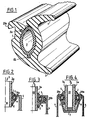
- Figure 1 shows the preferred configuration of the deformable seal according to the invention, in particular made of a material based on elastomer or plastomer or the like, or in a mixture based on these materials.
- This seal comprises two sealing lips 1, 2 intended to come into abutment against a window 3 (cf. FIG. 2) and to allow, in known manner, to adapt the seal to the play existing between this window and its frame. support 4 by relative spacing of the sealing lips.
- this clearance is likely to vary for other reasons, which are specified below, and this is to adapt with a single type of seal to these play variations that the seal according to the invention has been designed.
- the adaptation of the seal to variations in play due to manufacturing tolerances is significantly improved by incorporating in its mass a core (also made of material based on elastomer or plastomer or the like , and in particular in TPE, or in a mixture based on these materials) whose hardness and / or density is less, or equal to or greater than that of the remaining mass (or body) of the joint which surrounds the core.
- a core also made of material based on elastomer or plastomer or the like , and in particular in TPE, or in a mixture based on these materials
- the aforementioned core is made extractable from the mass which surrounds it.
- This advantage consists in that the user needs to have, for a given application, a single type of seal in accordance with the invention, which can be used either as it is, that is to say with the core incorporated, when it is a question of filling the clearance due to the only variations of tolerances, or without core when it is a question of filling a clearance reduced to a minimum value imposed, for example, by the adoption in last resort of '' double glazing of greater thickness in a given frame, while compensating for variations in play due to manufacturing tolerances.
- the core according to the invention can be made extractable in particular by using the teachings of Patent FR-77/12512, also in the name of the Applicant.
- the core can be constituted by at least two distinct portions, in particular when the core is hollowed out (this embodiment not having been shown for reasons of simplification).
- the aforementioned core can be full, but also and preferably hollowed out, like the core 5 shown in FIG. 1 which includes a recess 9 having no communication with the outside. Although for the configuration illustrated in Figure 1 the recess is formed inside, it is easy to imagine being able to provide a recess opening to the outside.
- the connection between the core and the mass which surrounds it is improved by means of anchoring ribs, such as 6 a and 6 b, projecting from the surface of the nucleus towards the mass which surrounds it.
- the core is preferably obtained by co-extrusion with the remaining mass of the seal which surrounds the core, which makes it possible, also by co-extrusion, to seal lips so that they have a hardness and / or a different density, namely, less, equal or greater than that of the seal body which surrounds the core, to adapt to the different needs of the practice.
- ribs of the aforementioned type can be formed alternatively or cumulatively in the remaining mass of the aforementioned joint which surrounds the core, as well as the mutual anchoring means between this core and the mass which surrounds it. a completely different configuration; for example, they may be in the form of tongues accessible from the outside and carried by one or other of the parts of which the seal according to the invention is made up and intended to ensure a sort of blocking of the core in said mass, the use of tongues being illustrated in the other embodiments which will be described later.
- Figures 2 and 3 illustrate the joint of Figure 1 in the working position and provided with anchoring means 20a and 201) (of type known per se) relative to the support frame 4 which make it a joint of the type known "to stuff” and “to clip", respectively, according to terminologies commonly used in the art and the meaning of which has already been given in the part of the description relating to the prior art.
- anchoring means can be provided with at least a portion (not shown for reasons of simplification of the drawings) of hardness and / or higher density, obtained by co-extrusion, to facilitate anchoring of the joint.
- the same seal according to the invention can be placed, for example, in a frame having a rebate of 25 mm and fitted with both 18 mm and 20 mm double glazing, while compensating for manufacturing tolerances, for example ⁇ 0.4 mm on the inside rebate of 25 mm and + 1.2 to - 0.7 mm on the total thickness of the double glazing of 18 or 20 mm.
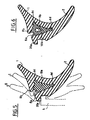
- Figure 5 shows in solid line another overall configuration of the seal according to the invention in the rest state, which differs from the configuration illustrated in Figure 1 for the presence of two anchoring or locking lips 8a and 8 b of the core 10 a - already provided with anchoring ribs 6 c and 6 d - in the remaining mass of the seal which surrounds it. These anchoring lips 8 a and 8 b are carried by the remaining mass of the seal which surrounds the core 10 a.
- the configurations I and Il in dotted lines are two extreme configurations in the deformed state of the seal, which correspond to two extreme values of the clearance (of the order of magnitude of several millimeters) existing between window (not shown) and frame 4, the gasket that can occupy continuously any intermediate configuration between the extreme configurations 1 and II above, depending on the play actually existing between window and frame.
- FIG. 6 shows a core 10 b provided with an internal recess 9 b, while the recess 9 c of the core 10 c in FIG. 7 opens to the outside, in the latter case, the anchoring function played by the lips 8 a and 8 b above being clearly imperative.
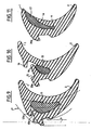
- FIG. 8 which illustrates a core 10 d provided with a recess 9 d opening to the outside
- the material constituting the core extends in particular beyond the lip anchoring corresponding to the reference numeral 8 a in FIGS. 5 to 7 and which, in this case, more exactly plays the role of anchoring rib 8 * carried by the remaining mass of the seal which surrounds the core 10 d, the extension 6 * d of the core 10 d corresponding to an anchoring lip thereof.
- Figure 9 illustrates in solid lines, another overall configuration of the joint according to the invention, which differs from the configuration of the joint of Figure 5 in that the anchoring lip 12 has the core - which, in this case , is a solid core denoted by the reference numeral 11 -, corresponding to the lip 8 in FIGS. 5 to 8, is thicker.
- the configuration in dotted line I * is a configuration in the deformed state of the seal without the core 11.
- the seal shown in FIG. 10 is provided with a core 13 whose retention in position is improved by a single anchoring lip 14 which is offset downward relative to the anchoring lip 20 a of the seal on or against the aforementioned support frame, so as to define a shoulder 15 against which a safety lip 16 can abut, the bringing of this lip in the abutment position corresponding to the maximum deformation tolerable by the seal and constituting a visual element allowing establish whether the state of deformation of the joint is acceptable.
- FIG. 11 illustrates another overall configuration of the seal according to the invention in which a core 17 - which comprises a single anchoring rib 6 - is formed in one of the sealing lips of the seal, and in particular in the external lip , instead of being formed in the body of the seal (from which the lips project towards the glass).
- a core 17 - which comprises a single anchoring rib 6 - is formed in one of the sealing lips of the seal, and in particular in the external lip , instead of being formed in the body of the seal (from which the lips project towards the glass).
Landscapes
- Engineering & Computer Science (AREA)
- Civil Engineering (AREA)
- Structural Engineering (AREA)
- Sealing Material Composition (AREA)
- Gasket Seals (AREA)
- Securing Of Glass Panes Or The Like (AREA)
- Sealing Devices (AREA)
- Package Closures (AREA)
- Control And Other Processes For Unpacking Of Materials (AREA)
Claims (20)
Priority Applications (1)
| Application Number | Priority Date | Filing Date | Title |
|---|---|---|---|
| AT87402067T ATE58947T1 (de) | 1986-09-19 | 1987-09-16 | Dichtungsprofil. |
Applications Claiming Priority (2)
| Application Number | Priority Date | Filing Date | Title |
|---|---|---|---|
| FR8613129A FR2604234B1 (fr) | 1986-09-19 | 1986-09-19 | Perfectionnements apportes aux joints d'etancheite. |
| FR8613129 | 1986-09-19 |
Publications (2)
| Publication Number | Publication Date |
|---|---|
| EP0263013A1 EP0263013A1 (de) | 1988-04-06 |
| EP0263013B1 true EP0263013B1 (de) | 1990-12-05 |
Family
ID=9339107
Family Applications (1)
| Application Number | Title | Priority Date | Filing Date |
|---|---|---|---|
| EP87402067A Expired - Lifetime EP0263013B1 (de) | 1986-09-19 | 1987-09-16 | Dichtungsprofil |
Country Status (6)
| Country | Link |
|---|---|
| EP (1) | EP0263013B1 (de) |
| AT (1) | ATE58947T1 (de) |
| DE (1) | DE3766583D1 (de) |
| ES (1) | ES2019960B3 (de) |
| FR (1) | FR2604234B1 (de) |
| GR (1) | GR3001541T3 (de) |
Families Citing this family (9)
| Publication number | Priority date | Publication date | Assignee | Title |
|---|---|---|---|---|
| CH680868A5 (de) * | 1990-08-13 | 1992-11-30 | Daetwyler Ag | |
| DE4241309C2 (de) * | 1992-12-08 | 1995-12-21 | Bruegmann Frisoplast Gmbh | Strangdichtungsprofil zur Abdichtung einer in einem Rahmen zwischen zwei umlaufenden Anschlagrippen angeordneten Glasscheibe |
| EP0854263A1 (de) * | 1997-01-16 | 1998-07-22 | Iseo Gomma S.p.A. | U-förmiges Dichtungsprofil für Fenster und Türrahmen |
| WO1999009284A1 (de) * | 1997-08-15 | 1999-02-25 | Wilfried Stuck | Gummidichtung |
| DE19933119C2 (de) * | 1999-07-19 | 2001-09-27 | Dorma Gmbh & Co Kg | Halterungsvorrichtung für Glasscheiben |
| DE102005050962A1 (de) * | 2005-10-25 | 2007-01-18 | Audi Ag | Dichtungsprofil |
| FR2934305A1 (fr) * | 2008-07-23 | 2010-01-29 | Hutchinson | Profile d'etancheite en particulier pour vitrage de fenetre de batiment, et fenetre l'incorporant |
| CN103423453B (zh) * | 2012-05-25 | 2016-12-14 | 珠海格力电器股份有限公司 | 密封条安装架及密封条安装组件 |
| FR2993304B1 (fr) * | 2012-07-13 | 2015-01-30 | Profils Systemes | Dispositif de montage d'un panneau vitre dans une menuiserie |
Citations (1)
| Publication number | Priority date | Publication date | Assignee | Title |
|---|---|---|---|---|
| US4537002A (en) * | 1983-09-08 | 1985-08-27 | Reese Enterprises, Inc. | Glazing bead structure |
Family Cites Families (15)
| Publication number | Priority date | Publication date | Assignee | Title |
|---|---|---|---|---|
| US2205538A (en) * | 1938-04-22 | 1940-06-25 | Pittsburgh Plate Glass Co | Window construction |
| US2454975A (en) * | 1946-04-05 | 1948-11-30 | Beech Aircraft Corp | Window molding |
| US2612972A (en) * | 1949-07-08 | 1952-10-07 | Gen Motors Corp | Sealing strip |
| DE972738C (de) * | 1951-01-25 | 1959-09-17 | Happich Gmbh Gebr | Fueller fuer in zwei Ausnehmungen plattenfoermige Teile aufnehmende Gummiprofile, insbesondere zur Befestigung von Fensterscheiben in Blechausschnitten von Karosserieaufbauten |
| GB750252A (en) * | 1953-10-14 | 1956-06-13 | Windshields Of Worcester Ltd | Improved glazing or mounting means for window and other panels |
| US3029481A (en) * | 1958-10-23 | 1962-04-17 | Henniges Ernst | Elastic compound sealing strip |
| FR1389474A (fr) * | 1963-11-04 | 1965-02-19 | Tech Jean Prouve | Dispositif de fixation de panneaux et notamment de glaces isolantes dans le bâtiment |
| BE685844A (de) * | 1966-08-23 | 1967-02-01 | ||
| DE1659533C2 (de) * | 1966-09-07 | 1982-06-09 | Franz 7807 Elzach Bayer | Dichtstreifen aus zwei Werkstoffen |
| US3456408A (en) * | 1967-09-14 | 1969-07-22 | Uniseal Inc | Sealing assembly for panels |
| DE2228605A1 (de) * | 1972-06-12 | 1974-01-03 | Theodor Straub | Vorrichtung zum einspannen eines flaechenelementes in einem rahmen |
| CH571639A5 (de) * | 1974-02-07 | 1976-01-15 | Daetwyler Ag | |
| CH601635A5 (de) * | 1975-08-04 | 1978-07-14 | Semperit Ag | |
| GB2093407A (en) * | 1981-01-23 | 1982-09-02 | Creators Ltd | Plastics trim strips |
| DE3324294A1 (de) * | 1983-07-06 | 1985-01-24 | Peter 7989 Argenbühl Schmidt | Badewanneneinsatz fuer behinderte |
-
1986
- 1986-09-19 FR FR8613129A patent/FR2604234B1/fr not_active Expired - Fee Related
-
1987
- 1987-09-16 DE DE8787402067T patent/DE3766583D1/de not_active Expired - Fee Related
- 1987-09-16 ES ES87402067T patent/ES2019960B3/es not_active Expired - Lifetime
- 1987-09-16 EP EP87402067A patent/EP0263013B1/de not_active Expired - Lifetime
- 1987-09-16 AT AT87402067T patent/ATE58947T1/de not_active IP Right Cessation
-
1991
- 1991-03-04 GR GR91400254T patent/GR3001541T3/el unknown
Patent Citations (1)
| Publication number | Priority date | Publication date | Assignee | Title |
|---|---|---|---|---|
| US4537002A (en) * | 1983-09-08 | 1985-08-27 | Reese Enterprises, Inc. | Glazing bead structure |
Also Published As
| Publication number | Publication date |
|---|---|
| ES2019960B3 (es) | 1991-07-16 |
| ATE58947T1 (de) | 1990-12-15 |
| GR3001541T3 (en) | 1992-11-23 |
| FR2604234B1 (fr) | 1990-06-01 |
| EP0263013A1 (de) | 1988-04-06 |
| DE3766583D1 (de) | 1991-01-17 |
| FR2604234A1 (fr) | 1988-03-25 |
Similar Documents
| Publication | Publication Date | Title |
|---|---|---|
| EP1203856B1 (de) | Fugenleiste | |
| WO2000028171A1 (fr) | Panneau de recouvrement pour parquet, lambris ou analogue | |
| EP0263013A1 (de) | Dichtungsprofil | |
| EP1034085A1 (de) | Verglasung mit einem profilierten band, das mit einem abdeckungsansatz versehen ist | |
| FR2845750A1 (fr) | Joint d'etancheite et vitrage isolant incorporant ce joint d'etancheite | |
| EP0021989B1 (de) | Dichtungsleisten für bewegliche Oberflächen | |
| EP1956173B1 (de) | Rahmen einer Schiebetür oder eines Schiebefensters, der einen verdeckten hohen Querriegel, Typ Monoblock, umfasst | |
| EP1033633A1 (de) | Vorrichtung zur dichten Befestigung eines Uhrglases an einem Uhrengehäuse | |
| FR2720443A1 (fr) | Joint d'étanchéité à l'huile pour turbine à gaz. | |
| EP0622516B1 (de) | Profil mit einem federnden Schenkel für das Abdecken eines Paneelrandes oder eines ersten Profiles, ein Rahmenelement und eine mit diesen Profilen versehene Tür | |
| FR2734019A1 (fr) | Garniture d'etancheite, en particulier pour fenetre vitree coulissante, et fenetre equipee d'une telle garniture | |
| FR2821113A1 (fr) | Attache anti-relevage pour volet roulant | |
| EP0284522A1 (de) | Einbruchhemmendes Vorsatzfenster | |
| EP0435748A1 (de) | Verbindungselement zwischen zwei Profilen | |
| EP0991155B1 (de) | Gehäuse, insbesondere für elektrische Geräte, dessen Rückwand mit mindestens einem, mit einer Kappe abgedeckten, Loch versehen ist | |
| EP2697467A1 (de) | Verbinder für hohlabschnitte von profilelementen, insbesondere für doppelglasfensterrahmen | |
| EP1646792A1 (de) | Profilleiste zur befestigung eines gespannten tuchs | |
| FR2700425A1 (fr) | Accessoire de goulotte et goulotte équipée d'un tel accessoire. | |
| EP2148037B1 (de) | Dichtungsprofil, insbesondere für eine Fensterscheibe in Gebäuden und ein Fenster, das damit ausgerüstet ist | |
| EP0882616B1 (de) | Vorrichtung zur Befestigung einer Fensterscheibe | |
| EP0764757B1 (de) | Dichtungsprofil, insbesondere für Verglasung | |
| FR2888605A1 (fr) | Composition de dormant pour porte, fenetre ou analogue. | |
| CH718724B1 (fr) | Boîte de montre munie d'une glace. | |
| EP0925978B1 (de) | Dichtungssystem für bewegliches Fenster | |
| FR2778942A1 (fr) | Bloc pour vitrage sur des chassis de portes ou de fenetres |
Legal Events
| Date | Code | Title | Description |
|---|---|---|---|
| PUAI | Public reference made under article 153(3) epc to a published international application that has entered the european phase |
Free format text: ORIGINAL CODE: 0009012 |
|
| AK | Designated contracting states |
Kind code of ref document: A1 Designated state(s): AT BE CH DE ES FR GB GR IT LI LU NL SE |
|
| 17P | Request for examination filed |
Effective date: 19880912 |
|
| 17Q | First examination report despatched |
Effective date: 19890916 |
|
| ITF | It: translation for a ep patent filed | ||
| GRAA | (expected) grant |
Free format text: ORIGINAL CODE: 0009210 |
|
| AK | Designated contracting states |
Kind code of ref document: B1 Designated state(s): AT BE CH DE ES FR GB GR IT LI LU NL SE |
|
| REF | Corresponds to: |
Ref document number: 58947 Country of ref document: AT Date of ref document: 19901215 Kind code of ref document: T |
|
| GBT | Gb: translation of ep patent filed (gb section 77(6)(a)/1977) | ||
| REF | Corresponds to: |
Ref document number: 3766583 Country of ref document: DE Date of ref document: 19910117 |
|
| ITTA | It: last paid annual fee | ||
| PLBE | No opposition filed within time limit |
Free format text: ORIGINAL CODE: 0009261 |
|
| STAA | Information on the status of an ep patent application or granted ep patent |
Free format text: STATUS: NO OPPOSITION FILED WITHIN TIME LIMIT |
|
| 26N | No opposition filed | ||
| REG | Reference to a national code |
Ref country code: GR Ref legal event code: FG4A Free format text: 3001541 |
|
| EPTA | Lu: last paid annual fee | ||
| EAL | Se: european patent in force in sweden |
Ref document number: 87402067.0 |
|
| PGFP | Annual fee paid to national office [announced via postgrant information from national office to epo] |
Ref country code: FR Payment date: 19970626 Year of fee payment: 11 |
|
| PGFP | Annual fee paid to national office [announced via postgrant information from national office to epo] |
Ref country code: DE Payment date: 19970701 Year of fee payment: 11 |
|
| PGFP | Annual fee paid to national office [announced via postgrant information from national office to epo] |
Ref country code: GR Payment date: 19970709 Year of fee payment: 11 |
|
| PGFP | Annual fee paid to national office [announced via postgrant information from national office to epo] |
Ref country code: SE Payment date: 19970804 Year of fee payment: 11 |
|
| PGFP | Annual fee paid to national office [announced via postgrant information from national office to epo] |
Ref country code: AT Payment date: 19970822 Year of fee payment: 11 |
|
| PGFP | Annual fee paid to national office [announced via postgrant information from national office to epo] |
Ref country code: CH Payment date: 19970828 Year of fee payment: 11 Ref country code: BE Payment date: 19970828 Year of fee payment: 11 |
|
| PGFP | Annual fee paid to national office [announced via postgrant information from national office to epo] |
Ref country code: GB Payment date: 19970903 Year of fee payment: 11 |
|
| PGFP | Annual fee paid to national office [announced via postgrant information from national office to epo] |
Ref country code: LU Payment date: 19970904 Year of fee payment: 11 |
|
| PGFP | Annual fee paid to national office [announced via postgrant information from national office to epo] |
Ref country code: ES Payment date: 19970926 Year of fee payment: 11 |
|
| PGFP | Annual fee paid to national office [announced via postgrant information from national office to epo] |
Ref country code: NL Payment date: 19970929 Year of fee payment: 11 |
|
| PG25 | Lapsed in a contracting state [announced via postgrant information from national office to epo] |
Ref country code: LU Free format text: LAPSE BECAUSE OF NON-PAYMENT OF DUE FEES Effective date: 19980916 Ref country code: GB Free format text: LAPSE BECAUSE OF NON-PAYMENT OF DUE FEES Effective date: 19980916 Ref country code: AT Free format text: LAPSE BECAUSE OF NON-PAYMENT OF DUE FEES Effective date: 19980916 |
|
| PG25 | Lapsed in a contracting state [announced via postgrant information from national office to epo] |
Ref country code: SE Free format text: LAPSE BECAUSE OF NON-PAYMENT OF DUE FEES Effective date: 19980917 Ref country code: ES Free format text: THE PATENT HAS BEEN ANNULLED BY A DECISION OF A NATIONAL AUTHORITY Effective date: 19980917 |
|
| PG25 | Lapsed in a contracting state [announced via postgrant information from national office to epo] |
Ref country code: LI Free format text: LAPSE BECAUSE OF NON-PAYMENT OF DUE FEES Effective date: 19980930 Ref country code: GR Free format text: LAPSE BECAUSE OF NON-PAYMENT OF DUE FEES Effective date: 19980930 Ref country code: CH Free format text: LAPSE BECAUSE OF NON-PAYMENT OF DUE FEES Effective date: 19980930 Ref country code: BE Free format text: LAPSE BECAUSE OF NON-PAYMENT OF DUE FEES Effective date: 19980930 |
|
| BERE | Be: lapsed |
Owner name: HUTCHINSON Effective date: 19980930 |
|
| PG25 | Lapsed in a contracting state [announced via postgrant information from national office to epo] |
Ref country code: NL Free format text: LAPSE BECAUSE OF NON-PAYMENT OF DUE FEES Effective date: 19990401 |
|
| GBPC | Gb: european patent ceased through non-payment of renewal fee |
Effective date: 19980916 |
|
| REG | Reference to a national code |
Ref country code: CH Ref legal event code: PL |
|
| EUG | Se: european patent has lapsed |
Ref document number: 87402067.0 |
|
| PG25 | Lapsed in a contracting state [announced via postgrant information from national office to epo] |
Ref country code: FR Free format text: LAPSE BECAUSE OF NON-PAYMENT OF DUE FEES Effective date: 19990531 |
|
| NLV4 | Nl: lapsed or anulled due to non-payment of the annual fee |
Effective date: 19990401 |
|
| PG25 | Lapsed in a contracting state [announced via postgrant information from national office to epo] |
Ref country code: DE Free format text: LAPSE BECAUSE OF NON-PAYMENT OF DUE FEES Effective date: 19990701 |
|
| REG | Reference to a national code |
Ref country code: FR Ref legal event code: ST |
|
| REG | Reference to a national code |
Ref country code: ES Ref legal event code: FD2A Effective date: 20001204 |
|
| PG25 | Lapsed in a contracting state [announced via postgrant information from national office to epo] |
Ref country code: IT Free format text: LAPSE BECAUSE OF NON-PAYMENT OF DUE FEES;WARNING: LAPSES OF ITALIAN PATENTS WITH EFFECTIVE DATE BEFORE 2007 MAY HAVE OCCURRED AT ANY TIME BEFORE 2007. THE CORRECT EFFECTIVE DATE MAY BE DIFFERENT FROM THE ONE RECORDED. Effective date: 20050916 |