EP0263076B1 - Bague pour garniture mécanique - Google Patents
Bague pour garniture mécanique Download PDFInfo
- Publication number
- EP0263076B1 EP0263076B1 EP87830276A EP87830276A EP0263076B1 EP 0263076 B1 EP0263076 B1 EP 0263076B1 EP 87830276 A EP87830276 A EP 87830276A EP 87830276 A EP87830276 A EP 87830276A EP 0263076 B1 EP0263076 B1 EP 0263076B1
- Authority
- EP
- European Patent Office
- Prior art keywords
- ring
- box
- shaped
- series
- moulded
- Prior art date
- Legal status (The legal status is an assumption and is not a legal conclusion. Google has not performed a legal analysis and makes no representation as to the accuracy of the status listed.)
- Expired
Links
- 229910000831 Steel Inorganic materials 0.000 claims abstract description 16
- 239000010959 steel Substances 0.000 claims abstract description 16
- 239000000463 material Substances 0.000 claims abstract description 11
- 239000004033 plastic Substances 0.000 claims abstract description 11
- 239000002991 molded plastic Substances 0.000 claims abstract description 10
- 238000010008 shearing Methods 0.000 claims abstract description 5
- 238000007789 sealing Methods 0.000 abstract description 12
- 239000002184 metal Substances 0.000 abstract description 6
- 229910052751 metal Inorganic materials 0.000 abstract description 6
- 238000000465 moulding Methods 0.000 abstract description 3
- 239000012768 molten material Substances 0.000 abstract description 2
- 238000004519 manufacturing process Methods 0.000 description 3
- 230000008878 coupling Effects 0.000 description 2
- 238000010168 coupling process Methods 0.000 description 2
- 238000005859 coupling reaction Methods 0.000 description 2
- OKTJSMMVPCPJKN-UHFFFAOYSA-N Carbon Chemical compound [C] OKTJSMMVPCPJKN-UHFFFAOYSA-N 0.000 description 1
- 229910001018 Cast iron Inorganic materials 0.000 description 1
- 229910001347 Stellite Inorganic materials 0.000 description 1
- 230000015572 biosynthetic process Effects 0.000 description 1
- 229910052799 carbon Inorganic materials 0.000 description 1
- 239000000919 ceramic Substances 0.000 description 1
- AHICWQREWHDHHF-UHFFFAOYSA-N chromium;cobalt;iron;manganese;methane;molybdenum;nickel;silicon;tungsten Chemical compound C.[Si].[Cr].[Mn].[Fe].[Co].[Ni].[Mo].[W] AHICWQREWHDHHF-UHFFFAOYSA-N 0.000 description 1
- 238000005553 drilling Methods 0.000 description 1
- 230000000694 effects Effects 0.000 description 1
- 238000000034 method Methods 0.000 description 1
- 238000012986 modification Methods 0.000 description 1
- 230000004048 modification Effects 0.000 description 1
- 238000003825 pressing Methods 0.000 description 1
Images

Classifications
-
- F—MECHANICAL ENGINEERING; LIGHTING; HEATING; WEAPONS; BLASTING
- F16—ENGINEERING ELEMENTS AND UNITS; GENERAL MEASURES FOR PRODUCING AND MAINTAINING EFFECTIVE FUNCTIONING OF MACHINES OR INSTALLATIONS; THERMAL INSULATION IN GENERAL
- F16J—PISTONS; CYLINDERS; SEALINGS
- F16J15/00—Sealings
- F16J15/16—Sealings between relatively-moving surfaces
- F16J15/34—Sealings between relatively-moving surfaces with slip-ring pressed against a more or less radial face on one member
- F16J15/3464—Mounting of the seal
Definitions
- This patent application for an industrial utility model concerns an improved ring for rotating mechanical seals, of the type with opposing slip-faces, using a moulded plastic or rubber ring to support a box-shaped steel ring whose surface has been machined to provide the ring-shaped lapped crown which constitutes the slip-face of the mechanical seal.
- the model can be considered as being an improved version of a prior art sealing ring (see e.g. GB-A- 2070702).
- the prior art sealing ring was designed with the aim of reducing the very high production costs of the sealing rings available up until that time which consisted, in general, of a couple of specially designed and produced rings made of carbon, ceramic, cast iron, special steel or stellite according to the user's requirements or preference.
- the sealing ring in question consists of a box-shaped ring obtained by shearing, drawing and then coining a strip of steel which is anchored to a supporting ring made of moulded plastic or rubber, the two parts being joined together by a series of buttons obtained by drilling a series of holes in the inner circular wall of the steel box-ring, into which the molten material flows during the moulding and then solidifies. Once the material has solidified, a series of projections locking the plastic or rubber body to the metal insert will have been formed.
- the box-shaped steel ring presents in the direction of the axis a "U" shaped cross section where the inner wing is longer than the outer one to allow for the above-mentioned series of holes which will be used for locking together with the corresponding buttons.
- the coupling and locking together of the metal box-shaped ring and the supporting ring can be effected equally well by two different procedures: the first, already mentioned, consisting of moulding the supporting ring in a mould where the metal box-shaped ring has previously inserted; the second, consisting of pressing the two autonomous and separately made parts together until they click into place.
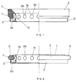
- the model according to the invention includes a ring (1) moulded in a plastic material whose characteristics make it suitable for this specific use, attached by means of a series of locking buttons (1a) to a metal box-shaped ring (2), obtained by shearing, drawing and then coining a strip of a special steel commonly used in the production of conventional mechanical sealing rings with slip-faces.
- a series of holes (2a) will also be made in the annular disk obtained. Once the disk is drawn, the holes will be situated on the inner cylindrical wall of the box-shaped piece and this inner wall will be longer than the outer one.
- the frontal face of the box-shaped ring (2) will be made slightly conical so as to determine the formation of a flat and polished, narrow, circular perimetral crown (2b) at which the contact and seal between the two ring-shaped slip-faces will be made once the lapping operation has been completed.
- Fig. 2 differs from Fig. 1 only in the profile of the external surface of the supporting ring (1).
- This variation has been presented solely to emphasize the fact that the use of a moulded plastic supporting ring permits any profile to be given to the ring itself without entailing any increase in the production costs.
- This feature is extremely interesting and valuable given that a rubber gasket (3) is usually applied to the outside of the mechanical sealing ring. Consequently the profile in negative of the rubber gasket can be reproduced and a perfect fit between the contact surfaces of the gasket (3) and the supporting ring (1) will be obtained.
- the ring could even be moulded directly in rubber so as to incorporate the gasket and thus avoid any problems of continuity, as is shown in Fig. 4, where number (4) in fact shows a moulded rubber ring with a conformation which permits it to act not only as a support for the box-shaped metal ring (2) but also as an external gasket.
- Fig. 3 shows the modifications to the conformation of the supporting ring which are necessary when it is to be joined to the box-shaped ring (2) by pressure with final click instead of being moulded using a mould where the box-shaped ring (2) has already been inserted (as described in the two embodiments illustrated in Figs. 1 and 2).
- a series of flexible tabs will be provided along the upper edge of the ring (1) by means of incising longitudinal grooves (1b) between the buttons (1a). These flexible tabs spread out radially when the two parts are pushed together until they click into place thus allowing the buttons (1a) to slip into the corresponding holes (2a).
Landscapes
- Engineering & Computer Science (AREA)
- General Engineering & Computer Science (AREA)
- Mechanical Engineering (AREA)
- Mechanical Sealing (AREA)
- Gasket Seals (AREA)
- Sealing Of Bearings (AREA)
- Sealing Using Fluids, Sealing Without Contact, And Removal Of Oil (AREA)
Claims (4)
- Anneau pour joints mécaniques rotatifs, du type à surfaces frottantes frontales, constitué d'un boîtier en acier (2) supporté par un anneau (1) moulé en matériel plastique ou en caoutchouc, caractérisé en ce que ledit boîtier en acier (2) est obtenu par cisaillement, bourrage et frappe d'un ruban d'acier, étant l'anneau de support (1) en plastique ou en caoutchouc accroché au boîtier en acier (2) au moyen d'une série circulaire de boutons (1a), encastrés dans autant de trous correspondants (2a), réalisés à cet effet sur la paroi cylindrique interne du boîtier (1) qui présente, sur un plan qui passe par l'axe, une section transversale en forme de "U" avec une aile externe plus basse, et sur la face frontale duquel on réalise une frappe apte à déterminer, suite à un successif polissage, une couronne circulaire périphérique (2b), plate et lisse, en correspondance de laquelle s'effectue le contact et l'étanchéité entre les surfaces frottantes.
- Anneau pour joints mécaniques rotatifs, selon la revendication 1), caractérisé en ce que l'accrochage entre le boîtier en acier (2) et l'anneau de support (1), moulé en plastique, s'effectue en injectant le matériel plastique dans un moule adapté dans lequel on a préalablement introduit et mis en place le boîtier en acier (2).
- Anneau pour joints mécaniques rotatifs, selon la revendication 1), caractérisé en ce que le boîtier en acier (2) et l'anneau de support (1), moulé en matériel plastique, sont fixés ensemble au moyen de couplage à déclic élastique en enfilant extérieurement ce dernier avec force sur la paroi cylindrique interne du boîtier, un bord arrondi de mise en place étant prévu sur les boutons d'accrochage (1a) ainsi qu'une série d'entailles (1b), entre bouton et bouton, déterminant pratiquement la formation d'autant de languettes élastiques le long du bord supérieur de l'anneau (1).
- Anneau pour joints mécaniques rotatifs, selon la revendication 1), caractérisé en ce que l'anneau de support résulte moulé en caoutchouc et incorpore, sans solution de continuité, l'anneau externe d'étanchéité.
Applications Claiming Priority (2)
| Application Number | Priority Date | Filing Date | Title |
|---|---|---|---|
| IT5658686 | 1986-07-18 | ||
| IT56586U | 1986-07-18 |
Publications (3)
| Publication Number | Publication Date |
|---|---|
| EP0263076A2 EP0263076A2 (fr) | 1988-04-06 |
| EP0263076A3 EP0263076A3 (en) | 1989-03-15 |
| EP0263076B1 true EP0263076B1 (fr) | 1992-02-19 |
Family
ID=11287985
Family Applications (1)
| Application Number | Title | Priority Date | Filing Date |
|---|---|---|---|
| EP87830276A Expired EP0263076B1 (fr) | 1986-07-18 | 1987-07-16 | Bague pour garniture mécanique |
Country Status (5)
| Country | Link |
|---|---|
| EP (1) | EP0263076B1 (fr) |
| AT (1) | ATE72696T1 (fr) |
| DE (1) | DE3776744D1 (fr) |
| ES (1) | ES2030095T3 (fr) |
| GR (1) | GR3004645T3 (fr) |
Families Citing this family (2)
| Publication number | Priority date | Publication date | Assignee | Title |
|---|---|---|---|---|
| DE4408846C1 (de) * | 1994-03-16 | 1995-04-13 | Freudenberg Carl Fa | Verfahren zur Herstellung einer Zentrierhülse |
| DE102011013366B4 (de) * | 2011-03-08 | 2014-10-02 | Federal-Mogul Burscheid Gmbh | Gleitringdichtung |
Family Cites Families (4)
| Publication number | Priority date | Publication date | Assignee | Title |
|---|---|---|---|---|
| GB1216416A (en) * | 1967-02-17 | 1970-12-23 | Patelec Cem Spa | Improvements in or relating to seals |
| FI64987C (fi) * | 1976-05-06 | 1984-02-10 | Freudenberg Carl Fa | Taetningselement foer spalten mellan tvao relativt varandra rorliga rotationssymmetriska delar |
| FR2454569A1 (fr) * | 1979-04-20 | 1980-11-14 | Hutchinson Mapa | Perfectionnements aux joints d'etancheite |
| JPS6035583B2 (ja) * | 1980-02-29 | 1985-08-15 | イ−グル工業株式会社 | メカニカルシ−ルの製造方法 |
-
1987
- 1987-07-16 EP EP87830276A patent/EP0263076B1/fr not_active Expired
- 1987-07-16 DE DE8787830276T patent/DE3776744D1/de not_active Expired - Lifetime
- 1987-07-16 AT AT87830276T patent/ATE72696T1/de not_active IP Right Cessation
- 1987-07-16 ES ES198787830276T patent/ES2030095T3/es not_active Expired - Lifetime
-
1992
- 1992-05-19 GR GR920400821T patent/GR3004645T3/el unknown
Also Published As
| Publication number | Publication date |
|---|---|
| GR3004645T3 (fr) | 1993-04-28 |
| ATE72696T1 (de) | 1992-03-15 |
| EP0263076A3 (en) | 1989-03-15 |
| EP0263076A2 (fr) | 1988-04-06 |
| ES2030095T3 (es) | 1992-10-16 |
| DE3776744D1 (de) | 1992-03-26 |
Similar Documents
| Publication | Publication Date | Title |
|---|---|---|
| AU591827B2 (en) | Wellhead seal assembly | |
| GR3017687T3 (en) | Ostomy coupling. | |
| GB2206801B (en) | Ostomy bag coupling | |
| GB1528218A (en) | Shaft seals | |
| JPS6123425B2 (fr) | ||
| ES444641A1 (es) | Procedimiento para fabricar un obturador de eje. | |
| GB2119674A (en) | Air filter element | |
| AU1009588A (en) | Wellhead annular seal | |
| EP0263076B1 (fr) | Bague pour garniture mécanique | |
| GB1535821A (en) | Elastic rotational couplings | |
| GB1472925A (en) | Packing | |
| GB1348111A (en) | Shaft coupling | |
| US4545688A (en) | Watch case having synthetic material seals between detachable parts thereof | |
| JPS63178667U (fr) | ||
| EP0242431A3 (en) | Sealing ring | |
| EP0823298A3 (fr) | Procédé et appareil pour la production de couvercles empilés et couvercles ainsi obtenus | |
| GB984032A (en) | Improvements relating to apparatus for manufacturing fluid seals for shafts and the like | |
| GB1358525A (en) | Grooved carbon brake discs | |
| JP2649067B2 (ja) | 密封装置の製造方法 | |
| Abdou-Sabet | Elastomeric Alloys--New TPE | |
| GB974554A (en) | Ball joint assemblies | |
| GB1370938A (en) | Manufacture of worm wheels | |
| GB191112161A (en) | Improvements in Cooking Bowls. | |
| GB1443712A (en) | Pipe couplings | |
| GB823341A (en) | Improvements in or relating to wheel rims |
Legal Events
| Date | Code | Title | Description |
|---|---|---|---|
| PUAI | Public reference made under article 153(3) epc to a published international application that has entered the european phase |
Free format text: ORIGINAL CODE: 0009012 |
|
| AK | Designated contracting states |
Kind code of ref document: A2 Designated state(s): AT BE CH DE ES FR GB GR LI LU NL SE |
|
| PUAL | Search report despatched |
Free format text: ORIGINAL CODE: 0009013 |
|
| AK | Designated contracting states |
Kind code of ref document: A3 Designated state(s): AT BE CH DE ES FR GB GR LI LU NL SE |
|
| 17P | Request for examination filed |
Effective date: 19891016 |
|
| 17Q | First examination report despatched |
Effective date: 19910729 |
|
| GRAA | (expected) grant |
Free format text: ORIGINAL CODE: 0009210 |
|
| AK | Designated contracting states |
Kind code of ref document: B1 Designated state(s): AT BE CH DE ES FR GB GR LI LU NL SE |
|
| REF | Corresponds to: |
Ref document number: 72696 Country of ref document: AT Date of ref document: 19920315 Kind code of ref document: T |
|
| REF | Corresponds to: |
Ref document number: 3776744 Country of ref document: DE Date of ref document: 19920326 |
|
| ET | Fr: translation filed | ||
| REG | Reference to a national code |
Ref country code: CH Ref legal event code: PUEA Free format text: I.M.A. (INDUSTRIA MECCANICA ACQUALAGNA) DI PAOLINI ARGENITO & C.S.N.C., - DANN AN - LAV FER DEI F.ILL. PAOLINI & C.S.R.L. Ref country code: CH Ref legal event code: PFA Free format text: I.M.A. (INDUSTRIA MECCANICA ACQUALAGNA S.R.L. |
|
| NLV1 | Nl: lapsed or annulled due to failure to fulfill the requirements of art. 29p and 29m of the patents act | ||
| REG | Reference to a national code |
Ref country code: ES Ref legal event code: FG2A Ref document number: 2030095 Country of ref document: ES Kind code of ref document: T3 |
|
| NLS | Nl: assignments of ep-patents |
Owner name: I.M.A. (INDUSTRIA MECCANICA ACQUALAGNA) DI PAOLINI |
|
| NLT1 | Nl: modifications of names registered in virtue of documents presented to the patent office pursuant to art. 16 a, paragraph 1 |
Owner name: I.M.A. INDUSTRIA MECCANICA ACQUALAGNA S.R.L. TE AC |
|
| PLBE | No opposition filed within time limit |
Free format text: ORIGINAL CODE: 0009261 |
|
| STAA | Information on the status of an ep patent application or granted ep patent |
Free format text: STATUS: NO OPPOSITION FILED WITHIN TIME LIMIT |
|
| BECA | Be: change of holder's address |
Free format text: 920626 *LAV FER DEI F. LLI PAOLINI & C. = S.R.L.:ZONA INDUSTRIALE CAP 61041, ACQUALAGNA (PS) - PIANO PIP |
|
| BECH | Be: change of holder |
Free format text: 920626 *LAV FER DEI F. LLI PAOLINI & C. = S.R.L. |
|
| BECN | Be: change of holder's name |
Effective date: 19920626 |
|
| NLS | Nl: assignments of ep-patents |
Owner name: LAV-FER DEI F.LLI. PAOLINI & C. S.R.L. TE ACQUALAG |
|
| REG | Reference to a national code |
Ref country code: GB Ref legal event code: 732E |
|
| REG | Reference to a national code |
Ref country code: GR Ref legal event code: FG4A Free format text: 3004645 |
|
| 26N | No opposition filed | ||
| REG | Reference to a national code |
Ref country code: FR Ref legal event code: TP Ref country code: FR Ref legal event code: CD Ref country code: FR Ref legal event code: CA |
|
| EPTA | Lu: last paid annual fee | ||
| EAL | Se: european patent in force in sweden |
Ref document number: 87830276.9 |
|
| REG | Reference to a national code |
Ref country code: GB Ref legal event code: IF02 |
|
| PGFP | Annual fee paid to national office [announced via postgrant information from national office to epo] |
Ref country code: GR Payment date: 20030715 Year of fee payment: 17 |
|
| PGFP | Annual fee paid to national office [announced via postgrant information from national office to epo] |
Ref country code: GB Payment date: 20030716 Year of fee payment: 17 Ref country code: ES Payment date: 20030716 Year of fee payment: 17 |
|
| PGFP | Annual fee paid to national office [announced via postgrant information from national office to epo] |
Ref country code: SE Payment date: 20030717 Year of fee payment: 17 |
|
| PGFP | Annual fee paid to national office [announced via postgrant information from national office to epo] |
Ref country code: BE Payment date: 20030729 Year of fee payment: 17 |
|
| PGFP | Annual fee paid to national office [announced via postgrant information from national office to epo] |
Ref country code: CH Payment date: 20030730 Year of fee payment: 17 |
|
| PGFP | Annual fee paid to national office [announced via postgrant information from national office to epo] |
Ref country code: NL Payment date: 20030731 Year of fee payment: 17 Ref country code: FR Payment date: 20030731 Year of fee payment: 17 Ref country code: AT Payment date: 20030731 Year of fee payment: 17 |
|
| PGFP | Annual fee paid to national office [announced via postgrant information from national office to epo] |
Ref country code: LU Payment date: 20030804 Year of fee payment: 17 |
|
| PGFP | Annual fee paid to national office [announced via postgrant information from national office to epo] |
Ref country code: DE Payment date: 20030925 Year of fee payment: 17 |
|
| PG25 | Lapsed in a contracting state [announced via postgrant information from national office to epo] |
Ref country code: LU Free format text: LAPSE BECAUSE OF NON-PAYMENT OF DUE FEES Effective date: 20040716 Ref country code: GB Free format text: LAPSE BECAUSE OF NON-PAYMENT OF DUE FEES Effective date: 20040716 Ref country code: AT Free format text: LAPSE BECAUSE OF NON-PAYMENT OF DUE FEES Effective date: 20040716 |
|
| PG25 | Lapsed in a contracting state [announced via postgrant information from national office to epo] |
Ref country code: SE Free format text: LAPSE BECAUSE OF NON-PAYMENT OF DUE FEES Effective date: 20040717 Ref country code: ES Free format text: LAPSE BECAUSE OF NON-PAYMENT OF DUE FEES Effective date: 20040717 |
|
| PG25 | Lapsed in a contracting state [announced via postgrant information from national office to epo] |
Ref country code: LI Free format text: LAPSE BECAUSE OF NON-PAYMENT OF DUE FEES Effective date: 20040731 Ref country code: CH Free format text: LAPSE BECAUSE OF NON-PAYMENT OF DUE FEES Effective date: 20040731 Ref country code: BE Free format text: LAPSE BECAUSE OF NON-PAYMENT OF DUE FEES Effective date: 20040731 |
|
| BERE | Be: lapsed |
Owner name: *LAV FER DEI F. LLI PAOLINI & C. S.R.L. Effective date: 20040731 |
|
| PG25 | Lapsed in a contracting state [announced via postgrant information from national office to epo] |
Ref country code: NL Free format text: LAPSE BECAUSE OF NON-PAYMENT OF DUE FEES Effective date: 20050201 Ref country code: DE Free format text: LAPSE BECAUSE OF NON-PAYMENT OF DUE FEES Effective date: 20050201 |
|
| PG25 | Lapsed in a contracting state [announced via postgrant information from national office to epo] |
Ref country code: GR Free format text: LAPSE BECAUSE OF NON-PAYMENT OF DUE FEES Effective date: 20050203 |
|
| EUG | Se: european patent has lapsed | ||
| GBPC | Gb: european patent ceased through non-payment of renewal fee |
Effective date: 20040716 |
|
| REG | Reference to a national code |
Ref country code: CH Ref legal event code: PL |
|
| PG25 | Lapsed in a contracting state [announced via postgrant information from national office to epo] |
Ref country code: FR Free format text: LAPSE BECAUSE OF NON-PAYMENT OF DUE FEES Effective date: 20050331 |
|
| NLV4 | Nl: lapsed or anulled due to non-payment of the annual fee |
Effective date: 20050201 |
|
| REG | Reference to a national code |
Ref country code: FR Ref legal event code: ST |
|
| REG | Reference to a national code |
Ref country code: ES Ref legal event code: FD2A Effective date: 20040717 |
|
| BERE | Be: lapsed |
Owner name: *LAV FER DEI F. LLI PAOLINI & C. S.R.L. Effective date: 20040731 |