EP0263088A2 - Drehbohrwerkzeug mit einem ausstellbaren Räumer - Google Patents
Drehbohrwerkzeug mit einem ausstellbaren Räumer Download PDFInfo
- Publication number
- EP0263088A2 EP0263088A2 EP87850287A EP87850287A EP0263088A2 EP 0263088 A2 EP0263088 A2 EP 0263088A2 EP 87850287 A EP87850287 A EP 87850287A EP 87850287 A EP87850287 A EP 87850287A EP 0263088 A2 EP0263088 A2 EP 0263088A2
- Authority
- EP
- European Patent Office
- Prior art keywords
- piece
- drill
- shaft
- hole
- reamer
- Prior art date
- Legal status (The legal status is an assumption and is not a legal conclusion. Google has not performed a legal analysis and makes no representation as to the accuracy of the status listed.)
- Granted
Links
Images


Classifications
-
- E—FIXED CONSTRUCTIONS
- E21—EARTH OR ROCK DRILLING; MINING
- E21B—EARTH OR ROCK DRILLING; OBTAINING OIL, GAS, WATER, SOLUBLE OR MELTABLE MATERIALS OR A SLURRY OF MINERALS FROM WELLS
- E21B10/00—Drill bits
- E21B10/26—Drill bits with leading portion, i.e. drill bits with a pilot cutter; Drill bits for enlarging the borehole, e.g. reamers
- E21B10/32—Drill bits with leading portion, i.e. drill bits with a pilot cutter; Drill bits for enlarging the borehole, e.g. reamers with expansible cutting tools
-
- E—FIXED CONSTRUCTIONS
- E21—EARTH OR ROCK DRILLING; MINING
- E21B—EARTH OR ROCK DRILLING; OBTAINING OIL, GAS, WATER, SOLUBLE OR MELTABLE MATERIALS OR A SLURRY OF MINERALS FROM WELLS
- E21B10/00—Drill bits
- E21B10/26—Drill bits with leading portion, i.e. drill bits with a pilot cutter; Drill bits for enlarging the borehole, e.g. reamers
- E21B10/32—Drill bits with leading portion, i.e. drill bits with a pilot cutter; Drill bits for enlarging the borehole, e.g. reamers with expansible cutting tools
- E21B10/327—Drill bits with leading portion, i.e. drill bits with a pilot cutter; Drill bits for enlarging the borehole, e.g. reamers with expansible cutting tools the cutter being pivoted about a longitudinal axis
Definitions
- the present invention relates to a drill with reamer piece for a sinker drill.
- Such drills are carried by a drill rod and accompanied by a casing-tube down into the drill hole. Drill cutting chippings are removed by flushing medium supplied to the drill through a channel in the drill rod.
- the drill is influenced by a hammer and also by rotation through the drill rod.
- the intention is that the ground shall not shift, so as to avoid cracks occurring in the buildings.
- this can be achieved by using a casing-tube to grout concrete pillars, at the same time filling any ground fissures with concrete.
- the ground surface can also be prepared by laying a horizontal surface to avoid displacements in the reinforcements.
- the object of the present invention is to provide an inexpensive and reliable drill comprising a reamer piece and a substantially cylindrical transition piece.
- This is achieved in practice by the central axis of the transition piece being made to coincide with the rotary axis of the drill rod and being provided with an eccentric, cylindrical hole, the central axis of the hole lying substantially parallel to the rotary axis of the drill rod, and the reamer piece being provided with a shaft to fit into the cylindrical hole, the axial length of the shaft substantially agreeing with the axial depth of the cylindrical hole, wherein the reamer piece with the shaft is axially movable in relation to the transition piece between the operating position A and the extraction position C, between which two positions the reamer piece assumes a swung-in position.
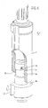
- the drill comprises a cylindrical transition piece 1 and a reamer piece 2 provided with hard metal cutting edges or pins arranged in substantially one plane.
- the transition piece 1 is secured in any suitable manner to a drill rod (not shown).
- the central axis of the transition piece coincides with the axis of rotation of the drill rod.
- An eccentric hole 4 is provided at the flat lower side of the transition piece 1, as well as a shoulder 6 having an inwardly facing flat, axial surface 8 made in one piece with the rest of the transition piece.
- the reamer piece 2 is provided with an eccentric shaft 3 for insertion into the hole 4.
- the axial length of the shaft 3 corresponds to the axial depth of the hole 4.
- the surface of the reamer piece 2 has an outwardly directed shoulder 5 cooperating with the shoulder 6 on the transition piece during drilling.
- the surface 8 of the transition piece also cooperates with a surface 7 on the reamer piece, this latter surface extending axially from the shoulder 5 to the plane in which the shaft 3 is arranged.
- the shaft 3 is provided with a narrowed waist 10, the axial depth thereof substantially corresponding to or slightly exceeding the axial length of the shoulder 6.
- the waist 10 is provided with an upward extension 11 towards the free end of the shaft, thus forming a shoulder 14 at the transition between waist extension 11 and shaft surface.
- Figure 4 shows the drill in operating position A.
- the free end of the shaft 3 is in contact with the bottom of the hole 4 in transition piece 1.
- the shoulders 5 and 6 of the reamer piece 2 and transition piece 1 also cooperate and a flat edge 15 on the lower end of transition piece 1 is in contact with a flat peripheral edge 16 on the upper end of the reamer piece 2.
- a pin 13 is inserted through an aperture in the wall of the transition piece, into the space defined by the narrowed waist 10 and the hole 4.
- the pin moves freely and is not subjected to any stress.
- the transition piece 1 and reamer piece 2 rotate together at the same speed as the drill rod.
- the hammer strikes in two planes, i.e. the plane defined by the upper end of the shaft and the bottom of the hole and the plane defined by the flat peripheral edge 15 and the flat peripheral edge 16.
- the reamer piece is swung out in the usual manner below the casing-tube, not shown.
- the invention permits the reamer piece to be swung in without alteration of the direction of rotation. Furthermore, the drill can be operated in any desired direction of rotation.
- the casing-tube, or an impact shoe provided at the lower end of the casing-tube, also has a storage function during reamer drilling according to the invention.
Landscapes
- Engineering & Computer Science (AREA)
- Geology (AREA)
- Mining & Mineral Resources (AREA)
- Life Sciences & Earth Sciences (AREA)
- General Life Sciences & Earth Sciences (AREA)
- Fluid Mechanics (AREA)
- Mechanical Engineering (AREA)
- Environmental & Geological Engineering (AREA)
- Physics & Mathematics (AREA)
- Geochemistry & Mineralogy (AREA)
- Earth Drilling (AREA)
- Pharmaceuticals Containing Other Organic And Inorganic Compounds (AREA)
- Catalysts (AREA)
- Drilling Tools (AREA)
- Processing Of Stones Or Stones Resemblance Materials (AREA)
Priority Applications (1)
| Application Number | Priority Date | Filing Date | Title |
|---|---|---|---|
| AT87850287T ATE84848T1 (de) | 1986-10-03 | 1987-09-23 | Drehbohrwerkzeug mit einem ausstellbaren raeumer. |
Applications Claiming Priority (2)
| Application Number | Priority Date | Filing Date | Title |
|---|---|---|---|
| SE8604207 | 1986-10-03 | ||
| SE8604207A SE460300B (sv) | 1986-10-03 | 1986-10-03 | Roterbart borrverktyg med upprymningsdel till en saenkborrmaskin |
Publications (3)
| Publication Number | Publication Date |
|---|---|
| EP0263088A2 true EP0263088A2 (de) | 1988-04-06 |
| EP0263088A3 EP0263088A3 (en) | 1989-03-22 |
| EP0263088B1 EP0263088B1 (de) | 1993-01-20 |
Family
ID=20365810
Family Applications (1)
| Application Number | Title | Priority Date | Filing Date |
|---|---|---|---|
| EP87850287A Expired - Lifetime EP0263088B1 (de) | 1986-10-03 | 1987-09-23 | Drehbohrwerkzeug mit einem ausstellbaren Räumer |
Country Status (11)
| Country | Link |
|---|---|
| US (1) | US4817741A (de) |
| EP (1) | EP0263088B1 (de) |
| AT (1) | ATE84848T1 (de) |
| AU (1) | AU591346B2 (de) |
| CA (1) | CA1328655C (de) |
| DE (1) | DE3783699T2 (de) |
| ES (1) | ES2037107T3 (de) |
| FI (1) | FI89624C (de) |
| IS (1) | IS1472B6 (de) |
| NO (1) | NO874160L (de) |
| SE (1) | SE460300B (de) |
Cited By (3)
| Publication number | Priority date | Publication date | Assignee | Title |
|---|---|---|---|---|
| EP0391873A3 (de) * | 1989-04-05 | 1991-04-03 | Uniroc Aktiebolag | Bohrwerkzeug |
| US5040621A (en) * | 1989-04-05 | 1991-08-20 | Uniroc Aktiebolag | Flushing means for drilling tools |
| US5944524A (en) * | 1996-07-25 | 1999-08-31 | Huels Aktiengesellschaft | Biohybrid dental implant |
Families Citing this family (4)
| Publication number | Priority date | Publication date | Assignee | Title |
|---|---|---|---|---|
| SE8901199L (sv) * | 1989-04-05 | 1990-10-06 | Uniroc Ab | Excentrisk borrkrona |
| US5009271A (en) * | 1990-07-16 | 1991-04-23 | Milan Maric | Drill assembly |
| GB2316964B (en) * | 1996-09-04 | 2000-06-07 | Bulroc | Drill means |
| CN113027343B (zh) * | 2021-04-12 | 2023-09-29 | 定边县泽林石油工程有限公司 | 一种偏心回转定位工具 |
Family Cites Families (10)
| Publication number | Priority date | Publication date | Assignee | Title |
|---|---|---|---|---|
| US1809820A (en) * | 1927-12-03 | 1931-06-16 | Grant John | Rotary underreamer |
| AU421138B2 (en) * | 1967-02-27 | 1972-02-07 | Ab Skanska Cementgjuteriet | Improvements in and relating to deep drills with eccentric bits |
| FR2409373A1 (fr) * | 1977-11-21 | 1979-06-15 | Stenuick France | Dispositif de forage de trous dans le sol, comportant un marteau pneumatique equipe d'un taillant excentre |
| GB2031481B (en) * | 1978-09-26 | 1982-09-29 | Marriott R | Drilling bits |
| AU536381B2 (en) * | 1980-03-26 | 1984-05-03 | Sandvik Ab | Drill tool |
| SU1033693A1 (ru) * | 1982-04-21 | 1983-08-07 | Предприятие П/Я М-5903 | Породоразрушающий инструмент дл ударно-вращательного бурени |
| GB2132252B (en) * | 1982-10-25 | 1985-12-18 | Tone Boring Co | An air hammer drill device |
| SE454196C (sv) * | 1983-09-23 | 1991-11-04 | Jan Persson | Jord- och bergborrningsanordning foer samtidig borrning och infodring av borrhaalet |
| SE458943B (sv) * | 1984-10-10 | 1989-05-22 | Jan Persson | Koppling mellan en borrkrona och borraxel |
| US4682662A (en) * | 1985-04-25 | 1987-07-28 | Vladimir Vancura | Drill adapter |
-
1986
- 1986-10-03 SE SE8604207A patent/SE460300B/sv not_active IP Right Cessation
-
1987
- 1987-09-23 AT AT87850287T patent/ATE84848T1/de not_active IP Right Cessation
- 1987-09-23 ES ES198787850287T patent/ES2037107T3/es not_active Expired - Lifetime
- 1987-09-23 DE DE8787850287T patent/DE3783699T2/de not_active Expired - Fee Related
- 1987-09-23 EP EP87850287A patent/EP0263088B1/de not_active Expired - Lifetime
- 1987-09-24 IS IS3263A patent/IS1472B6/is unknown
- 1987-10-02 US US07/103,655 patent/US4817741A/en not_active Expired - Lifetime
- 1987-10-02 FI FI874342A patent/FI89624C/fi not_active IP Right Cessation
- 1987-10-02 AU AU79307/87A patent/AU591346B2/en not_active Ceased
- 1987-10-02 NO NO874160A patent/NO874160L/no unknown
- 1987-10-02 CA CA000548518A patent/CA1328655C/en not_active Expired - Fee Related
Cited By (4)
| Publication number | Priority date | Publication date | Assignee | Title |
|---|---|---|---|---|
| EP0391873A3 (de) * | 1989-04-05 | 1991-04-03 | Uniroc Aktiebolag | Bohrwerkzeug |
| US5009274A (en) * | 1989-04-05 | 1991-04-23 | Uniroc Aktiebolag | Laterally adjustable drilling tool |
| US5040621A (en) * | 1989-04-05 | 1991-08-20 | Uniroc Aktiebolag | Flushing means for drilling tools |
| US5944524A (en) * | 1996-07-25 | 1999-08-31 | Huels Aktiengesellschaft | Biohybrid dental implant |
Also Published As
| Publication number | Publication date |
|---|---|
| SE8604207D0 (sv) | 1986-10-03 |
| NO874160D0 (no) | 1987-10-02 |
| FI874342L (fi) | 1988-04-04 |
| US4817741A (en) | 1989-04-04 |
| NO874160L (no) | 1988-04-05 |
| DE3783699T2 (de) | 1993-05-19 |
| EP0263088A3 (en) | 1989-03-22 |
| ES2037107T3 (es) | 1993-06-16 |
| SE8604207L (sv) | 1988-04-04 |
| AU7930787A (en) | 1988-04-14 |
| ATE84848T1 (de) | 1993-02-15 |
| SE460300B (sv) | 1989-09-25 |
| FI89624B (fi) | 1993-07-15 |
| EP0263088B1 (de) | 1993-01-20 |
| IS3263A7 (is) | 1988-04-04 |
| FI89624C (fi) | 1993-10-25 |
| AU591346B2 (en) | 1989-11-30 |
| DE3783699D1 (de) | 1993-03-04 |
| FI874342A0 (fi) | 1987-10-02 |
| IS1472B6 (is) | 1991-09-24 |
| CA1328655C (en) | 1994-04-19 |
Similar Documents
| Publication | Publication Date | Title |
|---|---|---|
| US3945444A (en) | Split bit casing drill | |
| KR101229209B1 (ko) | 하나의 굴착공에서 일반,확공을 병행할 수 있는 해머비트 및 이를 이용한 시공방법 | |
| NO317067B1 (no) | Kombinert fres- og borkrone | |
| US5823276A (en) | Diamond-tipped core barrel and method of using same | |
| EP0263088A2 (de) | Drehbohrwerkzeug mit einem ausstellbaren Räumer | |
| KR102614415B1 (ko) | 확공용 굴착 드릴 및 굴착 시스템 | |
| KR101434244B1 (ko) | 드릴 비트 및 단일 드릴 기구 | |
| KR101796425B1 (ko) | 캠 이동식 확경비트를 구비한 해머 비트 | |
| US3407889A (en) | Drill bit with an eccentric cutting edge portion | |
| US1905497A (en) | Working implement for percussive tools | |
| CA1047026A (en) | Tool for cutting groove in hole | |
| KR20200079384A (ko) | 동력 절약 및 부품 교환이 용이한 굴착용 링비트 | |
| JPH04302693A (ja) | 掘削工法 | |
| CN216110554U (zh) | 一种螺旋钻机用旋挖钻头 | |
| KR200248161Y1 (ko) | 암반 천공장치 | |
| US3598193A (en) | Cutter bits with radially extendable cutter elements | |
| GB2172315A (en) | Expandable-contractable drilling device | |
| CA2620473A1 (en) | A one-piece drill bit for single-pass anchor bolting and single pass drilling apparatus | |
| RU2119036C1 (ru) | Универсальный уширитель | |
| CN116677399B (zh) | 一种应急救援钻进疏障装置及使用方法 | |
| CN219774062U (zh) | 一种双套管锚杆钻机钻头 | |
| JPS6229597B2 (de) | ||
| JPS636313Y2 (de) | ||
| JPH0853987A (ja) | さく岩用工具及びさく岩方法 | |
| JPS62248792A (ja) | 岩盤等にスロツトを形成するための穿孔機のビツト |
Legal Events
| Date | Code | Title | Description |
|---|---|---|---|
| PUAI | Public reference made under article 153(3) epc to a published international application that has entered the european phase |
Free format text: ORIGINAL CODE: 0009012 |
|
| AK | Designated contracting states |
Kind code of ref document: A2 Designated state(s): AT BE CH DE ES FR GB IT LI SE |
|
| PUAL | Search report despatched |
Free format text: ORIGINAL CODE: 0009013 |
|
| AK | Designated contracting states |
Kind code of ref document: A3 Designated state(s): AT BE CH DE ES FR GB IT LI SE |
|
| 17P | Request for examination filed |
Effective date: 19890918 |
|
| 17Q | First examination report despatched |
Effective date: 19910806 |
|
| GRAA | (expected) grant |
Free format text: ORIGINAL CODE: 0009210 |
|
| AK | Designated contracting states |
Kind code of ref document: B1 Designated state(s): AT BE CH DE ES FR GB IT LI SE |
|
| PG25 | Lapsed in a contracting state [announced via postgrant information from national office to epo] |
Ref country code: SE Effective date: 19930120 |
|
| REF | Corresponds to: |
Ref document number: 84848 Country of ref document: AT Date of ref document: 19930215 Kind code of ref document: T |
|
| ITF | It: translation for a ep patent filed | ||
| ET | Fr: translation filed | ||
| REF | Corresponds to: |
Ref document number: 3783699 Country of ref document: DE Date of ref document: 19930304 |
|
| REG | Reference to a national code |
Ref country code: ES Ref legal event code: FG2A Ref document number: 2037107 Country of ref document: ES Kind code of ref document: T3 |
|
| PLBE | No opposition filed within time limit |
Free format text: ORIGINAL CODE: 0009261 |
|
| STAA | Information on the status of an ep patent application or granted ep patent |
Free format text: STATUS: NO OPPOSITION FILED WITHIN TIME LIMIT |
|
| 26N | No opposition filed | ||
| PGFP | Annual fee paid to national office [announced via postgrant information from national office to epo] |
Ref country code: FR Payment date: 19950911 Year of fee payment: 9 |
|
| PGFP | Annual fee paid to national office [announced via postgrant information from national office to epo] |
Ref country code: AT Payment date: 19950914 Year of fee payment: 9 |
|
| PGFP | Annual fee paid to national office [announced via postgrant information from national office to epo] |
Ref country code: DE Payment date: 19950928 Year of fee payment: 9 Ref country code: ES Payment date: 19950928 Year of fee payment: 9 |
|
| PGFP | Annual fee paid to national office [announced via postgrant information from national office to epo] |
Ref country code: CH Payment date: 19951020 Year of fee payment: 9 |
|
| PGFP | Annual fee paid to national office [announced via postgrant information from national office to epo] |
Ref country code: BE Payment date: 19951031 Year of fee payment: 9 |
|
| PG25 | Lapsed in a contracting state [announced via postgrant information from national office to epo] |
Ref country code: AT Effective date: 19960923 |
|
| PG25 | Lapsed in a contracting state [announced via postgrant information from national office to epo] |
Ref country code: ES Free format text: LAPSE BECAUSE OF NON-PAYMENT OF DUE FEES Effective date: 19960924 |
|
| PG25 | Lapsed in a contracting state [announced via postgrant information from national office to epo] |
Ref country code: FR Effective date: 19960930 Ref country code: BE Effective date: 19960930 Ref country code: LI Effective date: 19960930 Ref country code: CH Effective date: 19960930 |
|
| BERE | Be: lapsed |
Owner name: LOVAB LOF OCH OSTLUND A.B. Effective date: 19960930 |
|
| REG | Reference to a national code |
Ref country code: CH Ref legal event code: PL |
|
| PG25 | Lapsed in a contracting state [announced via postgrant information from national office to epo] |
Ref country code: DE Effective date: 19970603 |
|
| REG | Reference to a national code |
Ref country code: FR Ref legal event code: ST |
|
| REG | Reference to a national code |
Ref country code: FR Ref legal event code: ST |
|
| REG | Reference to a national code |
Ref country code: GB Ref legal event code: IF02 |
|
| REG | Reference to a national code |
Ref country code: ES Ref legal event code: FD2A Effective date: 19971011 |
|
| PGFP | Annual fee paid to national office [announced via postgrant information from national office to epo] |
Ref country code: GB Payment date: 20050921 Year of fee payment: 19 |
|
| PG25 | Lapsed in a contracting state [announced via postgrant information from national office to epo] |
Ref country code: IT Free format text: LAPSE BECAUSE OF NON-PAYMENT OF DUE FEES Effective date: 20050923 |
|
| GBPC | Gb: european patent ceased through non-payment of renewal fee |
Effective date: 20060923 |
|
| PG25 | Lapsed in a contracting state [announced via postgrant information from national office to epo] |
Ref country code: GB Free format text: LAPSE BECAUSE OF NON-PAYMENT OF DUE FEES Effective date: 20060923 |