EP0263143B1 - Scanner optique de haute resolution - Google Patents
Scanner optique de haute resolution Download PDFInfo
- Publication number
- EP0263143B1 EP0263143B1 EP87902217A EP87902217A EP0263143B1 EP 0263143 B1 EP0263143 B1 EP 0263143B1 EP 87902217 A EP87902217 A EP 87902217A EP 87902217 A EP87902217 A EP 87902217A EP 0263143 B1 EP0263143 B1 EP 0263143B1
- Authority
- EP
- European Patent Office
- Prior art keywords
- scanner
- mirror
- optical
- light beam
- intercept
- Prior art date
- Legal status (The legal status is an assumption and is not a legal conclusion. Google has not performed a legal analysis and makes no representation as to the accuracy of the status listed.)
- Expired
Links
- 230000003287 optical effect Effects 0.000 title claims abstract description 38
- 238000007493 shaping process Methods 0.000 claims abstract description 4
- 230000001154 acute effect Effects 0.000 claims 1
- 238000006073 displacement reaction Methods 0.000 description 5
- 230000004075 alteration Effects 0.000 description 2
- 201000009310 astigmatism Diseases 0.000 description 2
- 238000006243 chemical reaction Methods 0.000 description 2
- 206010010071 Coma Diseases 0.000 description 1
- 230000001427 coherent effect Effects 0.000 description 1
- 230000000694 effects Effects 0.000 description 1
- 238000005070 sampling Methods 0.000 description 1
Images

Classifications
-
- H—ELECTRICITY
- H04—ELECTRIC COMMUNICATION TECHNIQUE
- H04N—PICTORIAL COMMUNICATION, e.g. TELEVISION
- H04N1/00—Scanning, transmission or reproduction of documents or the like, e.g. facsimile transmission; Details thereof
- H04N1/04—Scanning arrangements, i.e. arrangements for the displacement of active reading or reproducing elements relative to the original or reproducing medium, or vice versa
- H04N1/12—Scanning arrangements, i.e. arrangements for the displacement of active reading or reproducing elements relative to the original or reproducing medium, or vice versa using the sheet-feed movement or the medium-advance or the drum-rotation movement as the slow scanning component, e.g. arrangements for the main-scanning
- H04N1/1205—Scanning arrangements, i.e. arrangements for the displacement of active reading or reproducing elements relative to the original or reproducing medium, or vice versa using the sheet-feed movement or the medium-advance or the drum-rotation movement as the slow scanning component, e.g. arrangements for the main-scanning using a device, e.g. an optical fibre bundle, converting rectilinear scanning into circular line scanning or vice versa
-
- G—PHYSICS
- G02—OPTICS
- G02B—OPTICAL ELEMENTS, SYSTEMS OR APPARATUS
- G02B26/00—Optical devices or arrangements for the control of light using movable or deformable optical elements
- G02B26/08—Optical devices or arrangements for the control of light using movable or deformable optical elements for controlling the direction of light
- G02B26/10—Scanning systems
- G02B26/12—Scanning systems using multifaceted mirrors
- G02B26/125—Details of the optical system between the polygonal mirror and the image plane
- G02B26/126—Details of the optical system between the polygonal mirror and the image plane including curved mirrors
-
- H—ELECTRICITY
- H04—ELECTRIC COMMUNICATION TECHNIQUE
- H04N—PICTORIAL COMMUNICATION, e.g. TELEVISION
- H04N1/00—Scanning, transmission or reproduction of documents or the like, e.g. facsimile transmission; Details thereof
- H04N1/04—Scanning arrangements, i.e. arrangements for the displacement of active reading or reproducing elements relative to the original or reproducing medium, or vice versa
- H04N1/207—Simultaneous scanning of the original picture and the reproduced picture with a common scanning device
-
- H—ELECTRICITY
- H04—ELECTRIC COMMUNICATION TECHNIQUE
- H04N—PICTORIAL COMMUNICATION, e.g. TELEVISION
- H04N1/00—Scanning, transmission or reproduction of documents or the like, e.g. facsimile transmission; Details thereof
- H04N1/04—Scanning arrangements, i.e. arrangements for the displacement of active reading or reproducing elements relative to the original or reproducing medium, or vice versa
- H04N1/113—Scanning arrangements, i.e. arrangements for the displacement of active reading or reproducing elements relative to the original or reproducing medium, or vice versa using oscillating or rotating mirrors
- H04N1/1135—Scanning arrangements, i.e. arrangements for the displacement of active reading or reproducing elements relative to the original or reproducing medium, or vice versa using oscillating or rotating mirrors for the main-scan only
-
- H—ELECTRICITY
- H04—ELECTRIC COMMUNICATION TECHNIQUE
- H04N—PICTORIAL COMMUNICATION, e.g. TELEVISION
- H04N2201/00—Indexing scheme relating to scanning, transmission or reproduction of documents or the like, and to details thereof
- H04N2201/04—Scanning arrangements
- H04N2201/0402—Arrangements not specific to a particular one of the scanning methods covered by groups H04N1/04 - H04N1/207
- H04N2201/0424—Scanning non-straight lines
Definitions
- the present invention relates to high resolution optical. scanners, and more particularly, to an optical scanner which corrects for alignment errors of a scanning polygon.
- High resolution optical scanners can be defined as scanners which produce from 10,000-50,000 resolutions, or spots, per scan. Such scanners are used in the graphics arts for scanning an image to be recorded and for printing on a receiving medium. Certain high resolution scanners move an optical head such that the optical system itself is essentially an on-axis system. These scanners are relatively slow compared with scanners which deflect a laser beam across the medium. However, in the deflecting- type scanners complex optical designs are necessary to achieve a large number of resolvable spots on the receiving medium.
- U.S. Patent No. US ⁇ A ⁇ 4,247,160 there is disclosed a laser beam scanner having a positive cylinder mirror located between the polygon deflector and a receiving medium.
- the positive cylinder mirror which has power in the sagittal plane but has no power in the tangential plane, minimizes spot position errors due to alignment errors between adjacent facets of the polygon deflector.
- corrective optical elements must be used in combination with the cylinder mirror as, for example, a post-deflector lens with appropriate power in the tangential plane.
- These optical elements in addition to adding to the complexity of the device, also introduce problems inherent in lenses, such as chromatic aberrations, which tend to limit the effectiveness of the scanner for high resolution scanning.
- the scanner is corrected for alignment errors of adjacent facets of the polygon, and uses only a single post-deflector element.
- a high resolution optical scanner for scanning a light beam onto a receiving medium, the scanner comprising a light source for generating a light beam, optical means for anamorphically shaping the beam, deflector means for intercepting the beam from the optical means and for moving the light beam through a predetermined scan angle in a tangential plane characterized in that said scanner uses only a single post-deflector element in the form of a mirror having optical power in both the tangential plane and in a sagittal plane which is positioned to intercept the light beam from the deflector means and direct the beam to the receiving medium.
- a spherical mirror is positioned to intercept a beam from a light source and direct the beam to a scanner, and to intercept the beam from the scanner and direct the beam to a receiving medium.
- the disclosed scanner has a flat field, a constant scan velocity (f ⁇ ), and it is corrected for pyramid error of the deflecting mirror. Also the scanner is color corrected, telecentric, and has only one post-deflector element. The combination of these features result in a scanner with very high resolution.
- An additional feature of the scanner is that there is no need for a separate element to be used as an anamorphic beam shaper for the input beam; the spherical mirror itself can be used as the shaper.
- the input beam which can be circularly symmetrical, is first reflected from the mirror to the scanner and is subsequently reflected from the mirror to the receiving medium.
- tangential refers to the plane containing both the principal ray and the central axis of a symmetric optical system, that is, the plane of scan of the scanning beam; and the term “sagittal” means the plane containing the principal ray which is normal to the tangential plane, that is the plane extending in the cross-scan direction and normal to the plane of scan.
- scan direction refers to the direction of movement of the scanning beam across the receiving medium, and the term “cross-scan direction” refers to the direction of movement of the receiving medium relative to the scanning beam.
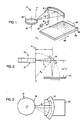
- FIG. 1 there is shown an optical scanner 10 constructed in accordance with the invention.
- a coherent light beam 12 from a light source 13 is directed by a mirror 14 to a spherical mirror 16.
- Light source 13 can be a conventional laser and can be modulated by an acousto-optic modulator (not shown) in a known manner.
- mirror 16 has a radius of curvature R s which extends from a point C on an axis of symmetry A.
- Mirror 16 directs beam 12 to a rotatable polygon 18 having a plurality of facets 20.
- the mirror 16 serves as an optical means to anamorphically shape the beam directed to polygon 18.
- the beam 12 from mirror 16 to polygon 18 is located at a relatively large off-axis angle so as to induce astigmatism.
- Polygon 18 serves as a deflector means for moving beam 12 through a predetermined scan angle.
- the polygon 18 directs the beam 12 back to spherical mirror 16 which in turn directs the beam onto a receiving medium 22 where scan lines 24 are formed.
- the scan direction of beam 12 is indicated by arrow 26, and the cross-scan direction is indicated by arrow 28.
- the polygon 18 is driven at a constant angular velocity by a motor (not shown).
- the receiving medium 22 can be a photosensitive member, for example, a photographic film, a photographic paper, a photoconductor used in a copier-duplicator, or any other means responsive to a source of light to produce an output image.
- the receiving member 22 is continuously driven in the cross-scan direction by suitable means (not shown). It will be understood that the beam 12 is line scanned at a much higher speed than the speed of the recording medium.
- the light beam 12 need not be monochromatic; it can also be polychromatic if it is desired to produce colored prints.
- the operation of polygons, lasers, optics and modulators are well understood in the art. For a more complete description of their operations, see Urbach et al, "Laser Scanning for Electronic Printing", Proceedings of the IEEE, 597 (June, 1982).
- the polygon 18 can be positioned on the axis of symmetry A, as shown in Figure 1.
- the location of the elements of scanner 10 can be determined by Coddington's equations, as follows:
- I is the tilt angle of mirror 16 (Fig. 2) which is the angle between the center line of the light beam which contacts the mirror surface and a line normal to the mirror surface at the point of contact of the center line;
- the beam 12 is focused in both scan and cross-scan directions on the receiving medium 22. It should also be noted that the polygon 18 and the receiving medium 22 are conjugate in the cross-scan direction. Thus, the system is corrected for polygon pyramid error.
- the optical scanner 10 has a flat field, that is the receiver plane is flat.
- the scan line is an arc with a radius of R/V2.
- Electronic means for performing such a conversion are known in the art.
- the scanner 10 is an f6 system since the scan position along the curved scan line is proportional to the scan angle.
- Scanner 10 as shown in Figures 1-3, has a magnification of -1 in the cross-scan direction; thus, coma is corrected.
- the astigmatism in scanner 10 is used to affect the beam anamorphically, and the spherical aberration is small.
- scanner 10 can be used without a separate anamorphic beam shaper for the input beam, since the mirror 16 is used as the shaper.
- the input beam 12, which can be circularly symmetrical, is reflected off the mirror 16, as shown in Figure 1.
- a polygon 18 which can be used in optical scanner 10 is a polygon having twelve facets 20, a diameter of 10 inches, and a duty cycle of 50%; thus, the total beam scan angle is 30°.
- the wavelength of beam 12 can be, for example, 0.83 microns, and the scanning beam radius is 21 microns.
- the displacement of a facet 20 along the optical axis during scanning is 1.1 mm.
- the beam size variation in the cross-scan direction due to this displacement is below 20%.
- Scanner 10 can also be used with a scanning beam having a radius less than 21 microns.
- the beam size variations in the cross-scan direction may be too large due to the axial translation of the polygon facets 20 as the polygon 18 rotates.
- a small cylindrical lens (not shown) can be positioned in the input beam and moved along the optical axis in synchronism with the polygon to compensate forthe beam waist displacement in the cross-scan direction.
- the size of beam 12 in the scan direction is not affected by the facet displacement, since beam 12 is collimated in the scan direction.
- the scanner 10 can operate with a galvanometer (not shown), or a one-facet polygon (not shown), positioned on axis A, instead of the polygon 18.
- a galvanometer using a galvanometer, R is 901.6 mm, the scan length is 33.02 cm, and the scanning beam size radius to the 1/e 2 point is 11 microns. For a sampling distance of 14 microns and a wavelength of beam 12 of 0.83 microns, over 23,000 resolvable spots are achieved.
- the radius of the curved scan line is 637.5 mm.
- FIGs 4 and 5 A further embodiment of applicant's invention is shown in Figures 4 and 5 in which there is disclosed an optical scanner 40 having a rotatable polygon 42, a toroid mirror 44 and a receiving medium 46.
- Scanner 40 is generally similar to scanner 10, with the exception that the toroid mirror 44 is used instead of the spherical mirror 16.
- Toroid mirror 44 can have a spherical or ellipsoidal profile in the sagittal plane and is circularly symmetrical about the axis A in the tangential plane.
- the letter designations, used for distances and the angle in scanner 40 (Figs. 4 and 5), are the same as those used for scanner 10, and Coddington's equations can be solved for scanner 40 in the same manner as for scanner 10.
- the input beam to toroid mirror 44 must be shaped to converge in the scan direction. Such beam shaping can be done with a cylindrical lens (not shown) located between laser 10 and mirror 44. A balance between the tangential and sagittal image curvature is achieved for magnification of -0.5 in the sagittal and +0.5 in the tangential planes. Since the longitudinal magnification is now 0.25 in both directions, the image depth of focus is reduced by a factor of 4 and the scanning beam size can be half the size of the one used with a spherical mirror. An advantage of using toroid mirror 44 is that the effects of axial displacement of facets 41 of the polygon 42 are minimized.
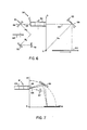
- FIG. 6 Another embodiment of applicant's invention is shown in Figure 6 in which there is disclosed an optical scanner 50 having an input scanner 51 and an output scanner 53, each of which functions generally in the same manner as scanner 10.
- Input scanner 51 comprises a spherical mirror 56 positioned to direct a beam 52 from a polygon 60 onto an object to be recorded, e.g., a film 62; and
- output scanner 53 comprises a spherical mirror 58 positioned to direct a beam 54 from polygon 60 onto a receiving medium 64.
- spherical mirror 56 receives beam 52 from a source (not shown) and directs beam 52 to polygon 60 at an angular position (on axis A') at one side of polygon 60; and mirror 58 receives beam 54 from a source (not shown) and directs beam 54 to polygon 60 at another angular position (on axis A) at an opposite side of polygon 60.
- a spherical mirror 70 is positioned to receive beam 52 after it passes through film 62 and direct the beam to a light detector 72. Signals from detector 72 can be processed and used to modulate beam 54 in a manner well known in the art.
- Input scanner 51 and output scanner 53 can have different format sizes as long as the scaling factors are the same in the scan and cross-scan directions. Although input scanner 51 and output scanner 53 are shown as both functioning with polygon 60, it will be apparent that a separate polygon could be used with each scanner 51, 53. Scanner 50 is especially advantageous in that data manipulation due to the curved scan line is not needed.
- an optical scanner 61 comprises a rotating polygon 63 and a spherical mirror 65 for scanning a beam onto a receiving medium M.
- An input beam 66 is inclined, as shown in Figure 7, to permit a symmetrical scan about a center scan point 68 on axis A. Since input beam 66 is not first directed against the spherical mirror 65 before being directed to polygon 63, as in scanner 10 (Figs. 1-3), beam 66 must pass through optical means as, for example, a cylindrical lens 67, to provide an input beam to the polygon 63 which is collimated in the tangential plane and focused on polygon 63 in the sagittal plane.
- the curvature of the scan line produced by scanner 61 will be somewhat different from the curvature of scan line 24 produced by scanner 10; however, the field flatness and f6 properties are the same in both embodiments.
Landscapes
- Engineering & Computer Science (AREA)
- Multimedia (AREA)
- Signal Processing (AREA)
- Physics & Mathematics (AREA)
- General Physics & Mathematics (AREA)
- Optics & Photonics (AREA)
- Mechanical Optical Scanning Systems (AREA)
- Facsimile Scanning Arrangements (AREA)
- Fax Reproducing Arrangements (AREA)
Abstract
Claims (11)
Applications Claiming Priority (2)
| Application Number | Priority Date | Filing Date | Title |
|---|---|---|---|
| US842579 | 1986-03-21 | ||
| US06/842,579 US4759593A (en) | 1986-03-21 | 1986-03-21 | High resolution optical scanner |
Publications (2)
| Publication Number | Publication Date |
|---|---|
| EP0263143A1 EP0263143A1 (fr) | 1988-04-13 |
| EP0263143B1 true EP0263143B1 (fr) | 1991-02-06 |
Family
ID=25287698
Family Applications (1)
| Application Number | Title | Priority Date | Filing Date |
|---|---|---|---|
| EP87902217A Expired EP0263143B1 (fr) | 1986-03-21 | 1987-03-09 | Scanner optique de haute resolution |
Country Status (5)
| Country | Link |
|---|---|
| US (1) | US4759593A (fr) |
| EP (1) | EP0263143B1 (fr) |
| JP (1) | JP2692825B2 (fr) |
| DE (1) | DE3767954D1 (fr) |
| WO (1) | WO1987005766A1 (fr) |
Families Citing this family (23)
| Publication number | Priority date | Publication date | Assignee | Title |
|---|---|---|---|---|
| US4863228A (en) * | 1987-02-10 | 1989-09-05 | Nakamichi Corporation | Apparatus and a method of deflecting laser convergent light |
| GB2248310A (en) * | 1987-12-09 | 1992-04-01 | Rank Xerox Ltd | Thermal imaging apparatus |
| JPH0364726A (ja) * | 1989-08-02 | 1991-03-20 | Minolta Camera Co Ltd | 光ビーム走査光学系 |
| JPH0364727A (ja) * | 1989-08-02 | 1991-03-20 | Minolta Camera Co Ltd | 光ビーム走査光学系 |
| US5004311A (en) * | 1989-10-27 | 1991-04-02 | Sri International | Beam scanning method and apparatus |
| JPH04194814A (ja) * | 1990-11-22 | 1992-07-14 | Minolta Camera Co Ltd | 光ビーム走査光学系 |
| JP3157550B2 (ja) * | 1991-02-28 | 2001-04-16 | 株式会社リコー | 等速光走査用結像反射鏡および光走査装置 |
| JPH05333268A (ja) * | 1992-06-03 | 1993-12-17 | Matsushita Electric Ind Co Ltd | 円弧照明装置 |
| NO301191B1 (no) * | 1993-05-13 | 1997-09-22 | Cargoscan As | Anordning ved måling av gjenstanders dimensjoner |
| JP3283678B2 (ja) * | 1994-01-26 | 2002-05-20 | 株式会社リコー | 光走査装置 |
| JP3031451B2 (ja) * | 1994-10-27 | 2000-04-10 | シャープ株式会社 | レーザ走査装置 |
| US5777751A (en) * | 1995-09-28 | 1998-07-07 | Eastman Kodak Company | Correction of curved scan lines in an optical scanning system |
| US5936756A (en) * | 1996-01-10 | 1999-08-10 | Ricoh Company Ltd. | Compact scanning optical system |
| JP3104633B2 (ja) * | 1997-02-26 | 2000-10-30 | 富士ゼロックス株式会社 | 光学走査装置及び画像形成装置 |
| US6052212A (en) * | 1998-12-14 | 2000-04-18 | Eastman Kodak Company | Method and apparatus for correcting coma in a high resolution scanner |
| US6441908B1 (en) * | 1999-08-06 | 2002-08-27 | Metron Systems, Inc. | Profiling of a component having reduced sensitivity to anomalous off-axis reflections |
| AU2003278985A1 (en) | 2002-09-26 | 2004-04-19 | Metron Systems, Inc. | Determination of the angular position of a laser beam |
| US6940891B2 (en) * | 2002-10-28 | 2005-09-06 | Metron Systems, Inc. | High precision optical imaging systems and related systems |
| AU2003285098A1 (en) * | 2002-10-29 | 2004-05-25 | Metron Systems, Inc. | Calibration for 3d measurement system |
| USD631478S1 (en) * | 2010-01-11 | 2011-01-25 | Datalogic Scanning, Inc. | Weigh platter or cover for a data reader |
| USD708183S1 (en) * | 2012-06-08 | 2014-07-01 | Datalogic ADC, Inc. | Data reader for checkout station |
| DE102012111423A1 (de) | 2012-11-26 | 2014-05-28 | Limo Patentverwaltung Gmbh & Co. Kg | Vorrichtung zur Ablenkung eines Lichtstrahls |
| DE102013108066A1 (de) | 2013-07-29 | 2015-01-29 | Limo Patentverwaltung Gmbh & Co. Kg | Vorrichtung zur Ablenkung eines Lichtstrahls |
Family Cites Families (22)
| Publication number | Priority date | Publication date | Assignee | Title |
|---|---|---|---|---|
| US3520586A (en) * | 1966-06-20 | 1970-07-14 | Ampex | Entrant beam optical scanner |
| US3817593A (en) * | 1971-11-11 | 1974-06-18 | Te Co | Image surface scanning system |
| US3984171A (en) * | 1974-08-21 | 1976-10-05 | Image Information Inc. | Linear scan system |
| JPS52135747A (en) * | 1976-05-10 | 1977-11-14 | Fuji Xerox Co Ltd | Optical device for compensating reflected light incident position by turning of mirror surface of rotary meltiisurface mirror |
| US4099830A (en) * | 1976-12-15 | 1978-07-11 | A. J. Bingley Limited | Optical systems including polygonal mirrors rotatable about two axes |
| JPS53144759A (en) * | 1977-05-24 | 1978-12-16 | Olympus Optical Co Ltd | Plane beam scanner |
| JPS54143661A (en) * | 1978-04-28 | 1979-11-09 | Canon Inc | Recording optical system |
| US4247160A (en) * | 1979-03-26 | 1981-01-27 | Xerox Corporation | Scanner with reflective pyramid error compensation |
| US4272151A (en) * | 1979-10-30 | 1981-06-09 | Balasubramanian N | Apparatus for optical scanning |
| DE3022365A1 (de) * | 1979-11-01 | 1981-05-14 | Barr & Stroud Ltd., Glasgow, Scotland | Optische abtastvorrichtung |
| JPS6055809B2 (ja) * | 1979-11-26 | 1985-12-06 | 大日本スクリ−ン製造株式会社 | 光走査方法 |
| US4397521A (en) * | 1980-09-29 | 1983-08-09 | Xerox Corporation | Double pass optical system for raster scanners |
| JPS57102609A (en) * | 1980-12-18 | 1982-06-25 | Canon Inc | Method and device for scanning using plural number of beams |
| JPS57144501A (en) * | 1981-03-03 | 1982-09-07 | Canon Inc | Scan optical system applied with moisture-resistant process |
| GB2115174B (en) * | 1981-11-25 | 1985-05-01 | Barr & Stroud Ltd | Optical scanning systems |
| SE433783B (sv) * | 1982-03-03 | 1984-06-12 | Pharos Ab | Optisk svepanordning |
| JPS58225774A (ja) * | 1982-06-23 | 1983-12-27 | Matsushita Electric Ind Co Ltd | 画像走査記録装置 |
| US4492970A (en) * | 1982-07-22 | 1985-01-08 | Minnesota Mining & Manufacturing Company | Laser diode printer |
| SE442067B (sv) * | 1984-04-26 | 1985-11-25 | Pharos Ab | Optisk svepanordning |
| JPS60257417A (ja) * | 1984-06-04 | 1985-12-19 | Fuji Xerox Co Ltd | 光ビ−ム走査装置 |
| US4588269A (en) * | 1984-07-05 | 1986-05-13 | Eastman Kodak Company | Apparatus which shapes gaussian beams by spherical mirrors |
| FR2576114B1 (fr) * | 1985-01-11 | 1987-02-13 | Trt Telecom Radio Electr | Analyseur optico-mecanique ayant un champ de telemetrie fixe |
-
1986
- 1986-03-21 US US06/842,579 patent/US4759593A/en not_active Expired - Lifetime
-
1987
- 1987-03-09 EP EP87902217A patent/EP0263143B1/fr not_active Expired
- 1987-03-09 WO PCT/US1987/000463 patent/WO1987005766A1/fr not_active Ceased
- 1987-03-09 JP JP62502060A patent/JP2692825B2/ja not_active Expired - Fee Related
- 1987-03-09 DE DE8787902217T patent/DE3767954D1/de not_active Expired - Fee Related
Also Published As
| Publication number | Publication date |
|---|---|
| WO1987005766A1 (fr) | 1987-09-24 |
| JP2692825B2 (ja) | 1997-12-17 |
| EP0263143A1 (fr) | 1988-04-13 |
| US4759593A (en) | 1988-07-26 |
| DE3767954D1 (de) | 1991-03-14 |
| JPH01500777A (ja) | 1989-03-16 |
Similar Documents
| Publication | Publication Date | Title |
|---|---|---|
| EP0263143B1 (fr) | Scanner optique de haute resolution | |
| US5526166A (en) | Optical system for the correction of differential scanline bow | |
| EP0697782B1 (fr) | Dispositif de formation d'image | |
| US5181137A (en) | Light scanning apparatus | |
| EP1111435B1 (fr) | Système de balayage optique comportant plusieurs éléments optiques de correction des oscillations parasites réduisant les dimensions du système | |
| EP0713323B1 (fr) | Dispositif de balayage à polygone multi-points avec optimisation de la profondeur de champ de séparation des lignes | |
| EP0947335B1 (fr) | Imprimante laser utilisant des groupes de laser multiples à longueurs d'onde multiples | |
| EP0299964B1 (fr) | Appareil d'exploration optique | |
| US5691759A (en) | Method and apparatus for interleaving raster scan lines in a multi-beam laser imaging device | |
| WO1991006028A1 (fr) | LENTILLE F-$g(U) | |
| EP0386226B1 (fr) | Dispositif optique de balayage | |
| US6621593B1 (en) | Scan line non-linearity correction using an aspheric element in a ROS system | |
| EP0526846B1 (fr) | Appareil de balayage optique à plusieurs faisceaux | |
| US4583816A (en) | Preobjective hologon scanner system | |
| EP1107038B1 (fr) | Système optique de balayage multi-faisceaux et appareil de formation d'images l'utilisant | |
| US6031561A (en) | Printer system having a plurality of light sources of different wavelengths | |
| WO1989012369A1 (fr) | Systeme de scanner a laser multi-faisceau | |
| US6172787B1 (en) | Laser beam scanning optical apparatus | |
| EP0843192B1 (fr) | Système de balayage optique | |
| US5838355A (en) | Printer system utilizing three different data rates | |
| EP0137559A1 (fr) | Dispositif d'exposition | |
| US5278691A (en) | Symmetrical overfilled polygon laser scanner | |
| JPH07111509B2 (ja) | 光走査装置 | |
| JP2000180749A (ja) | 光走査装置 | |
| JPH0619494B2 (ja) | 光走査装置 |
Legal Events
| Date | Code | Title | Description |
|---|---|---|---|
| PUAI | Public reference made under article 153(3) epc to a published international application that has entered the european phase |
Free format text: ORIGINAL CODE: 0009012 |
|
| 17P | Request for examination filed |
Effective date: 19871121 |
|
| AK | Designated contracting states |
Kind code of ref document: A1 Designated state(s): DE FR GB |
|
| 17Q | First examination report despatched |
Effective date: 19891221 |
|
| GRAA | (expected) grant |
Free format text: ORIGINAL CODE: 0009210 |
|
| AK | Designated contracting states |
Kind code of ref document: B1 Designated state(s): DE FR GB |
|
| REF | Corresponds to: |
Ref document number: 3767954 Country of ref document: DE Date of ref document: 19910314 |
|
| ET | Fr: translation filed | ||
| PLBE | No opposition filed within time limit |
Free format text: ORIGINAL CODE: 0009261 |
|
| STAA | Information on the status of an ep patent application or granted ep patent |
Free format text: STATUS: NO OPPOSITION FILED WITHIN TIME LIMIT |
|
| 26N | No opposition filed | ||
| REG | Reference to a national code |
Ref country code: GB Ref legal event code: IF02 |
|
| PGFP | Annual fee paid to national office [announced via postgrant information from national office to epo] |
Ref country code: GB Payment date: 20020205 Year of fee payment: 16 |
|
| PGFP | Annual fee paid to national office [announced via postgrant information from national office to epo] |
Ref country code: FR Payment date: 20020228 Year of fee payment: 16 |
|
| PGFP | Annual fee paid to national office [announced via postgrant information from national office to epo] |
Ref country code: DE Payment date: 20020327 Year of fee payment: 16 |
|
| PG25 | Lapsed in a contracting state [announced via postgrant information from national office to epo] |
Ref country code: GB Free format text: LAPSE BECAUSE OF NON-PAYMENT OF DUE FEES Effective date: 20030309 |
|
| PG25 | Lapsed in a contracting state [announced via postgrant information from national office to epo] |
Ref country code: DE Free format text: LAPSE BECAUSE OF NON-PAYMENT OF DUE FEES Effective date: 20031001 |
|
| GBPC | Gb: european patent ceased through non-payment of renewal fee |
Effective date: 20030309 |
|
| PG25 | Lapsed in a contracting state [announced via postgrant information from national office to epo] |
Ref country code: FR Free format text: LAPSE BECAUSE OF NON-PAYMENT OF DUE FEES Effective date: 20031127 |
|
| REG | Reference to a national code |
Ref country code: FR Ref legal event code: ST |