EP0263215A1 - Kolbenstangenloser Zylinder - Google Patents
Kolbenstangenloser Zylinder Download PDFInfo
- Publication number
- EP0263215A1 EP0263215A1 EP86309360A EP86309360A EP0263215A1 EP 0263215 A1 EP0263215 A1 EP 0263215A1 EP 86309360 A EP86309360 A EP 86309360A EP 86309360 A EP86309360 A EP 86309360A EP 0263215 A1 EP0263215 A1 EP 0263215A1
- Authority
- EP
- European Patent Office
- Prior art keywords
- cylinder
- piston
- drive block
- guide
- rodless
- Prior art date
- Legal status (The legal status is an assumption and is not a legal conclusion. Google has not performed a legal analysis and makes no representation as to the accuracy of the status listed.)
- Granted
Links
- 239000012530 fluid Substances 0.000 claims abstract description 14
- 238000007789 sealing Methods 0.000 claims abstract description 7
- 238000013459 approach Methods 0.000 claims abstract 2
- 230000000694 effects Effects 0.000 description 3
- 229920003023 plastic Polymers 0.000 description 3
- 230000035939 shock Effects 0.000 description 3
- 239000002184 metal Substances 0.000 description 2
- 229910000831 Steel Inorganic materials 0.000 description 1
- 230000001133 acceleration Effects 0.000 description 1
- 239000004744 fabric Substances 0.000 description 1
- 229920002457 flexible plastic Polymers 0.000 description 1
- 230000002028 premature Effects 0.000 description 1
- 230000000284 resting effect Effects 0.000 description 1
- 239000010959 steel Substances 0.000 description 1
Images


Classifications
-
- F—MECHANICAL ENGINEERING; LIGHTING; HEATING; WEAPONS; BLASTING
- F15—FLUID-PRESSURE ACTUATORS; HYDRAULICS OR PNEUMATICS IN GENERAL
- F15B—SYSTEMS ACTING BY MEANS OF FLUIDS IN GENERAL; FLUID-PRESSURE ACTUATORS, e.g. SERVOMOTORS; DETAILS OF FLUID-PRESSURE SYSTEMS, NOT OTHERWISE PROVIDED FOR
- F15B15/00—Fluid-actuated devices for displacing a member from one position to another; Gearing associated therewith
- F15B15/08—Characterised by the construction of the motor unit
- F15B15/084—Characterised by the construction of the motor unit the motor being of the rodless piston type, e.g. with cable, belt or chain
Definitions
- This invention relates to a fluid operated piston and cylinder arrangement which does not utilize a piston rod. These arrangements are known in the art as rodless cylinders.
- Rodless cylinders of the prior art comprise an elongated cylinder member containing a piston which is movable within the cylinder from one end to the other. This movement is responsive to the introduction of pressurized fluid into the cylindrical member.
- a flexible cable is secured to each end of the piston each cable passing through seals in the ends of the cylinders and around a pulley at each end of the cylinder with the outer ends of the cables being secured to opposite sides of a drive block.
- United States Patent No. 4,057,257 which issued on November 8, 1977 to Tol-O-Matic Inc. is representative of this type of prior art.
- Various types of guides are utilized for supporting the reciprocating drive block, these either resting upon the outer wall of the cylinder or being separate guides supported away from the cylinder.
- the cables which transfer the motion from the piston to the drive block must be kept under a slight tension so that during use the mechanism operates precisely with no slack occurring in either of the cables.
- the operation of a rodless cylinder is very rapid and there is little cushioning effect at the ends of the stroke with the result being that excessively large forces have to be contended with after the rapid acceleration of the cylinder from a stationary position.
- Large tension loads in the cables are therefore encountered which stretch the cables during use. The effects of such stretching cannot be tolerated and therefore an adjustment mechanism is required so that the cables can be periodically tensioned.
- rodless cylinders are often located in a dirty environment which leads to premature wear of the guides which support the reciprocating drive block and also of the cables and pulleys.
- the rodless cylinder of this invention consists of a guide support for the reciprocating drive block, a cylinder beneath the guide support, the cylinder including a piston having a cable from each end which passes through a seal at each end of the cylinder, around a pulley and to each respective end of a drive block.
- the drive block is preferably supported and guided upon the guide support by rollers secured to the drive block.
- Each end of the cylinder is provided with an axially extending compressible support means which has a disk valve which closes the exit from the cylinder when the piston is a set distance from the end of the cylinder.
- the remaining travel of the cylinder therefore compresses fluid in the cylinder and provides smooth retardation of the piston.
- a relief valve is utilized at both ends of the cylinder so that the degree of cushioning effect upon the piston can be limited.
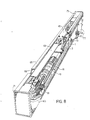
- the rodless cylinder is enclosed on both sides and the ends preferably by sheet or cast metal or plastic, and a wide groove is left along most of the length of the upper surface.
- Each side of this groove has a slotted guide and a flat belt is secured to the drive block and passes in both longitudinal directions through the slotted guide, around each pulley and below the cylinder.
- the unit is therefore totally enclosed and can be used in a dirty environment.
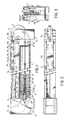
- the rodless cylinder of this invention consists of a channel shaped guide support 1 having tracks or rails 3 secured to the upper ends of the flanges of the channel by countersunk tap bolts or other convenient means (not shown).
- the channel is bolted by bolts 5 to a cylinder 7 through cylinder ends 6.
- a pulley 11 is rotatably supported at an extension 9 from each end 9 by a shaft 13 held in conventional bearings 15 (not detailed).
- Set screw 17 or a roll pin or other securing means is used to attach each pulley to its respective shaft.
- a piston 19 is within cylinder 7 and includes conventional piston ring grooves and piston rings shown generally at 21. From each end of the piston 19 there are drilled concentric bores 23 and 25. Into bore 23, which is threaded, there is screwed an end connection 27 to which a cable 29 is firmly secured.
- the bore 25 includes a compressible resilient member such as a coil spring 31, which acts between the shoulder 33 at the juncture of bores 23 and 25, and an annular disk sealing member 35 which can co-operate with a valve seat 37 in the end cap 6, or with a bore 8 in the end cap and then the valve seat 37, or solely with bore 39 in the end cap.
- the cable 29 passes through bore 39 and a seal 41 in the end cap 6.
- the cable 29 passes around pulley 11 and is secured to a drive block system which consists of two integral side end blocks 47 and a centre block 49.
- the centre block 49 can be dispensed with if required.
- a top plate 45 is bolted to the blocks.
- cam rollers 51, 53 and 55 which preferably utilize needle bearings, to support the drive block assembly for constrained reciprocal movement along the rails 3.
- Rollers 51 and 55 are preferably eccentrically mounted so that adjustments towards and way from the guides can be made.
- End blocks 47 have a passage 43 therethrough to accept threaded ends connection 59 on cables 29 which have nuts 61 to provide tensioning adjustment for the cables. Belleville washers 60 are provided below the nuts 61 to accommodate minor changes due to cable stretching.
- End caps 71 which can conveniently be cast are secured to each end of the cover 63 by screws 73, and, after the addition of small upper end scraper plates 75 between the ends of grooves 67, the internal mechanism of the rodless cylinder will be completely enclosed.
- Support brackets 77 are secured by bolts 79 to extensions 9.
- pressurized fluid enters through one of the ports 12, 14, a pipe 16 leading fluid from port 12 to the left hand end cap, passes through bore 39 and forces the piston 19 along the cylinder 7 so moving the drive block mechanism and the belt 69.
- annular disk seal 35 contacts at least seat 37 and p revents the exit of fluid from the opposite end of the piston.
- the resilient member 31 is preferably of a length such that fluid is prevented from leaving the cylinder at a location wherein the fluid cushion will be longer than the piston length.
- the pressure relief valve 81 is preferably adjustable and also preferably has a leakdown which may be adjustable.
- a rodless cylinder which is constructed to lessen excessive shock loads upon the cables connecting the piston to the drive block mechanism so that stretching of the cables is minimized and adjustment is rarely required to tension the cables.
- the rodless cylinder also has a high strength guide channel which is equipped with rigid steel rails and needle bearing cam rollers which provides a degree of drive block load control which is not presently available in this art.
- the rodless cylinder is also completely enclosed so that it can be used in a dirty environment.
Landscapes
- Engineering & Computer Science (AREA)
- Physics & Mathematics (AREA)
- Fluid Mechanics (AREA)
- Mechanical Engineering (AREA)
- General Engineering & Computer Science (AREA)
- Actuator (AREA)
- Acyclic And Carbocyclic Compounds In Medicinal Compositions (AREA)
Priority Applications (1)
| Application Number | Priority Date | Filing Date | Title |
|---|---|---|---|
| AT86309360T ATE66051T1 (de) | 1986-09-05 | 1986-12-01 | Kolbenstangenloser zylinder. |
Applications Claiming Priority (2)
| Application Number | Priority Date | Filing Date | Title |
|---|---|---|---|
| CA000517623A CA1260360A (en) | 1986-09-05 | 1986-09-05 | Rodless cylinder |
| CA517623 | 1986-09-05 |
Publications (2)
| Publication Number | Publication Date |
|---|---|
| EP0263215A1 true EP0263215A1 (de) | 1988-04-13 |
| EP0263215B1 EP0263215B1 (de) | 1991-08-07 |
Family
ID=4133867
Family Applications (1)
| Application Number | Title | Priority Date | Filing Date |
|---|---|---|---|
| EP86309360A Expired - Lifetime EP0263215B1 (de) | 1986-09-05 | 1986-12-01 | Kolbenstangenloser Zylinder |
Country Status (6)
| Country | Link |
|---|---|
| US (1) | US4796515A (de) |
| EP (1) | EP0263215B1 (de) |
| JP (1) | JPS6367409A (de) |
| AT (1) | ATE66051T1 (de) |
| CA (1) | CA1260360A (de) |
| DE (1) | DE3680792D1 (de) |
Cited By (4)
| Publication number | Priority date | Publication date | Assignee | Title |
|---|---|---|---|---|
| DE3822103A1 (de) * | 1988-06-30 | 1990-02-08 | Winkler Duennebier Kg Masch | Vorrichtung zum verschieben von teilen |
| EP0708254A3 (de) * | 1994-10-18 | 1998-03-25 | IMI Norgren GmbH | Druckmittelbetätigter Arbeitszylinder |
| EP0828083A3 (de) * | 1996-09-06 | 1998-05-06 | Deutsche Star GmbH | Linearführungseinheit |
| US5974904A (en) * | 1996-09-06 | 1999-11-02 | Deutsche Star Gmbh | Linear guide device |
Families Citing this family (11)
| Publication number | Priority date | Publication date | Assignee | Title |
|---|---|---|---|---|
| DE3905561C2 (de) * | 1989-02-23 | 1995-04-20 | Rexroth Pneumatik Mannesmann | Druckmittelbetätigbarer Arbeitszylinder |
| DE4027636C2 (de) * | 1990-08-31 | 1994-03-17 | Airtec Pneumatic Gmbh | Fluidgetriebener kolbenstangenloser Arbeitszylinder |
| DE4029721C3 (de) * | 1990-09-17 | 1997-04-03 | Mannesmann Ag | Kolbenstangenloser Zylinder |
| US5806439A (en) * | 1997-04-23 | 1998-09-15 | Concept Unlimited Inc. | Transport system for automatic teller machines |
| US5836256A (en) * | 1997-07-02 | 1998-11-17 | Concept Unlimited Inc | Apparatus for moving automatic teller machines between retracted and extended positions |
| US5996469A (en) * | 1998-04-07 | 1999-12-07 | Greenco Manufacturing Corporation | Rodless power cylinder |
| US6336393B1 (en) | 1998-07-01 | 2002-01-08 | Parker-Hannifin Corporation | Rodless pneumatic cylinder |
| KR100316471B1 (ko) | 1998-09-01 | 2001-12-12 | 김용래 | 로드리스 실린더 |
| KR20040023038A (ko) * | 2002-09-10 | 2004-03-18 | 김용래 | 로드리스 실린더 |
| EP2469029A1 (de) | 2010-12-22 | 2012-06-27 | Siemens Aktiengesellschaft | Prallkühlung von Gasturbinenschaufeln |
| FR2990485B1 (fr) * | 2012-05-09 | 2021-04-23 | Commissariat Energie Atomique | Arbre de transmission flexible, et verin a cable a moteur deporte utilisant un tel arbre |
Citations (6)
| Publication number | Priority date | Publication date | Assignee | Title |
|---|---|---|---|---|
| US2556698A (en) * | 1945-02-05 | 1951-06-12 | G F Goodson | Piston construction |
| DE1206561B (de) * | 1962-10-13 | 1965-12-09 | Cie Parisienne D Outil A Air C | Vorrichtung zum Daempfen der Hubbewegung des Kolbens eines Hubzylinders |
| FR1538718A (fr) * | 1967-08-29 | 1968-09-06 | Commande alternée hydraulique ou à air comprimé avec piston à double effet avec pression symétrique transmise par câble assurant l'effort de poussée et applicable aux crics, appareils de levage ou autres emplois | |
| DE2404244A1 (de) * | 1974-01-30 | 1975-08-07 | Ahrendt & Birkendahl Ohg | Kolbenstangenloser arbeitszylinder |
| DE2325882B2 (de) * | 1972-09-01 | 1978-04-27 | Veb Kombinat Orsta-Hydraulik, Ddr 7010 Leipzig | Einrichtung zur Endlagenbremsung in pneumatischen Arbeitszylindern |
| EP0135041A1 (de) * | 1983-08-10 | 1985-03-27 | Robert Bosch Gmbh | Kolbenstangenloser Arbeitszylinder |
Family Cites Families (17)
| Publication number | Priority date | Publication date | Assignee | Title |
|---|---|---|---|---|
| US1799366A (en) * | 1929-03-13 | 1931-04-07 | Heinkel Ernst | Device for airplane-launching apparatus |
| US2130982A (en) * | 1934-03-06 | 1938-09-20 | Sullivan Machinery Co | Rock drill |
| US2103252A (en) * | 1934-03-06 | 1937-12-28 | Sullivan Machinery Co | Rock drill |
| US2535899A (en) * | 1946-10-17 | 1950-12-26 | H Y Bassett | Antenna |
| US3136225A (en) * | 1962-01-29 | 1964-06-09 | Harold K Rader | Piston cushioning structure |
| US3157095A (en) * | 1962-04-12 | 1964-11-17 | Elmer F Heiser | Piston and cylinder device |
| US3173337A (en) * | 1962-09-14 | 1965-03-16 | Hardinge Brothers Inc | Hydraulic variable speed feed mechanism for machine tools and the like |
| US3559771A (en) * | 1968-07-02 | 1971-02-02 | Tol O Matic Inc | Brake motor |
| US3667552A (en) * | 1970-06-03 | 1972-06-06 | John Edward Gordon | Cable feed device |
| US3745888A (en) * | 1971-11-24 | 1973-07-17 | Gen Motors Corp | Fluid operated linear motor |
| US3820446A (en) * | 1971-12-20 | 1974-06-28 | Origa Cylindrar Ab | Means at pressure fluid cylinders |
| US3885654A (en) * | 1974-04-05 | 1975-05-27 | Ford Motor Co | Deceleration device and valve mechanism |
| US4139182A (en) * | 1975-11-26 | 1979-02-13 | Tokico Ltd. | Spring device |
| US4057257A (en) * | 1977-01-10 | 1977-11-08 | Tol-O-Matic, Inc. | Seal assembly |
| US4373427A (en) * | 1980-01-31 | 1983-02-15 | Tol-O-Matic, Inc. | Fluid pressure cylinder |
| DE3016696C2 (de) * | 1980-04-30 | 1986-09-04 | Robert Bosch Gmbh, 7000 Stuttgart | Bandzylinder mit einem durch ein Fluid angetriebenen Kolben |
| US4364303A (en) * | 1980-09-08 | 1982-12-21 | Sumida Kunio A | Air operated reciprocating tool |
-
1986
- 1986-09-05 CA CA000517623A patent/CA1260360A/en not_active Expired
- 1986-12-01 AT AT86309360T patent/ATE66051T1/de active
- 1986-12-01 EP EP86309360A patent/EP0263215B1/de not_active Expired - Lifetime
- 1986-12-01 DE DE8686309360T patent/DE3680792D1/de not_active Expired - Lifetime
- 1986-12-29 JP JP61316021A patent/JPS6367409A/ja active Pending
-
1987
- 1987-01-12 US US07/002,740 patent/US4796515A/en not_active Expired - Fee Related
Patent Citations (6)
| Publication number | Priority date | Publication date | Assignee | Title |
|---|---|---|---|---|
| US2556698A (en) * | 1945-02-05 | 1951-06-12 | G F Goodson | Piston construction |
| DE1206561B (de) * | 1962-10-13 | 1965-12-09 | Cie Parisienne D Outil A Air C | Vorrichtung zum Daempfen der Hubbewegung des Kolbens eines Hubzylinders |
| FR1538718A (fr) * | 1967-08-29 | 1968-09-06 | Commande alternée hydraulique ou à air comprimé avec piston à double effet avec pression symétrique transmise par câble assurant l'effort de poussée et applicable aux crics, appareils de levage ou autres emplois | |
| DE2325882B2 (de) * | 1972-09-01 | 1978-04-27 | Veb Kombinat Orsta-Hydraulik, Ddr 7010 Leipzig | Einrichtung zur Endlagenbremsung in pneumatischen Arbeitszylindern |
| DE2404244A1 (de) * | 1974-01-30 | 1975-08-07 | Ahrendt & Birkendahl Ohg | Kolbenstangenloser arbeitszylinder |
| EP0135041A1 (de) * | 1983-08-10 | 1985-03-27 | Robert Bosch Gmbh | Kolbenstangenloser Arbeitszylinder |
Cited By (5)
| Publication number | Priority date | Publication date | Assignee | Title |
|---|---|---|---|---|
| DE3822103A1 (de) * | 1988-06-30 | 1990-02-08 | Winkler Duennebier Kg Masch | Vorrichtung zum verschieben von teilen |
| EP0708254A3 (de) * | 1994-10-18 | 1998-03-25 | IMI Norgren GmbH | Druckmittelbetätigter Arbeitszylinder |
| EP0828083A3 (de) * | 1996-09-06 | 1998-05-06 | Deutsche Star GmbH | Linearführungseinheit |
| US5868499A (en) * | 1996-09-06 | 1999-02-09 | Deutsche Star Gmbh | Linear guiding unit |
| US5974904A (en) * | 1996-09-06 | 1999-11-02 | Deutsche Star Gmbh | Linear guide device |
Also Published As
| Publication number | Publication date |
|---|---|
| US4796515A (en) | 1989-01-10 |
| CA1260360A (en) | 1989-09-26 |
| ATE66051T1 (de) | 1991-08-15 |
| DE3680792D1 (de) | 1991-09-12 |
| EP0263215B1 (de) | 1991-08-07 |
| JPS6367409A (ja) | 1988-03-26 |
Similar Documents
| Publication | Publication Date | Title |
|---|---|---|
| EP0263215A1 (de) | Kolbenstangenloser Zylinder | |
| EP0603459B2 (de) | Gleitstellglied | |
| US5195391A (en) | Linear guiding and driving unit | |
| CA2058390C (en) | Camshaft adjuster and tensioner | |
| KR960000574B1 (ko) | 로드레스 실린더 | |
| US5097716A (en) | Linear guiding and driving unit | |
| US5273367A (en) | Linear motion rolling guide unit and a vibration isolation apparatus used in the unit | |
| US4051742A (en) | Arrangement for tensioning and guiding the belts of a cellular plastic forming machine | |
| US4744287A (en) | Rodless cylinder | |
| KR0174751B1 (ko) | 선형 엑추에이터 | |
| US4737093A (en) | Die locking mechanism for a molding apparatus | |
| DE2144688C3 (de) | Keilriemen-Spannvorrichtung | |
| KR100395631B1 (ko) | 가이드기구 | |
| US6422964B1 (en) | Belt tensioner, and a drive system and engine including such a tensioner | |
| US4256032A (en) | Improved strap guide system | |
| US5699891A (en) | Device for displacing workpiece carriers | |
| KR100237518B1 (ko) | 유체 탄성 디이프 드로잉 장치 | |
| US3390823A (en) | Web guide apparatus | |
| DE3012277A1 (de) | Arretierungsvorrichtung | |
| US4726801A (en) | Belt or chain tension tensioner | |
| US5483868A (en) | Braking apparatus for a rodless piston actuated reciprocating carriage | |
| US4347784A (en) | Bearings for calender rolls and supports therefor | |
| US5776516A (en) | Two-platen injection molding machine | |
| KR920014537A (ko) | 연속주조설비에 있어서 분배채널등의 스토퍼(Stopper)의 제어된 조정을 위한 장치 | |
| US5593018A (en) | Apparatus for shifting work carriers |
Legal Events
| Date | Code | Title | Description |
|---|---|---|---|
| PUAI | Public reference made under article 153(3) epc to a published international application that has entered the european phase |
Free format text: ORIGINAL CODE: 0009012 |
|
| AK | Designated contracting states |
Kind code of ref document: A1 Designated state(s): AT BE CH DE ES FR GB GR IT LI LU NL SE |
|
| 17P | Request for examination filed |
Effective date: 19880822 |
|
| 17Q | First examination report despatched |
Effective date: 19890123 |
|
| GRAA | (expected) grant |
Free format text: ORIGINAL CODE: 0009210 |
|
| AK | Designated contracting states |
Kind code of ref document: B1 Designated state(s): AT BE CH DE ES FR GB GR IT LI LU NL SE |
|
| PG25 | Lapsed in a contracting state [announced via postgrant information from national office to epo] |
Ref country code: IT Free format text: LAPSE BECAUSE OF FAILURE TO SUBMIT A TRANSLATION OF THE DESCRIPTION OR TO PAY THE FEE WITHIN THE PRE;WARNING: LAPSES OF ITALIAN PATENTS WITH EFFECTIVE DATE BEFORE 2007 MAY HAVE OCCURRED AT ANY TIME BEFORE 2007. THE CORRECT EFFECTIVE DATE MAY BE DIFFERENT FROM THE ONE RECORDED.SCRIBED TIME-LIMIT Effective date: 19910807 Ref country code: BE Effective date: 19910807 Ref country code: AT Effective date: 19910807 Ref country code: LI Effective date: 19910807 Ref country code: NL Effective date: 19910807 Ref country code: SE Effective date: 19910807 Ref country code: CH Effective date: 19910807 Ref country code: GR Free format text: LAPSE BECAUSE OF FAILURE TO SUBMIT A TRANSLATION OF THE DESCRIPTION OR TO PAY THE FEE WITHIN THE PRESCRIBED TIME-LIMIT Effective date: 19910807 |
|
| REF | Corresponds to: |
Ref document number: 66051 Country of ref document: AT Date of ref document: 19910815 Kind code of ref document: T |
|
| REF | Corresponds to: |
Ref document number: 3680792 Country of ref document: DE Date of ref document: 19910912 |
|
| ET | Fr: translation filed | ||
| PGFP | Annual fee paid to national office [announced via postgrant information from national office to epo] |
Ref country code: GB Payment date: 19911104 Year of fee payment: 6 |
|
| REG | Reference to a national code |
Ref country code: CH Ref legal event code: PL |
|
| PG25 | Lapsed in a contracting state [announced via postgrant information from national office to epo] |
Ref country code: ES Free format text: LAPSE BECAUSE OF FAILURE TO SUBMIT A TRANSLATION OF THE DESCRIPTION OR TO PAY THE FEE WITHIN THE PRESCRIBED TIME-LIMIT Effective date: 19911118 |
|
| PGFP | Annual fee paid to national office [announced via postgrant information from national office to epo] |
Ref country code: FR Payment date: 19911128 Year of fee payment: 6 |
|
| PGFP | Annual fee paid to national office [announced via postgrant information from national office to epo] |
Ref country code: DE Payment date: 19911227 Year of fee payment: 6 |
|
| PG25 | Lapsed in a contracting state [announced via postgrant information from national office to epo] |
Ref country code: LU Free format text: LAPSE BECAUSE OF NON-PAYMENT OF DUE FEES Effective date: 19911231 |
|
| NLV1 | Nl: lapsed or annulled due to failure to fulfill the requirements of art. 29p and 29m of the patents act | ||
| PLBE | No opposition filed within time limit |
Free format text: ORIGINAL CODE: 0009261 |
|
| STAA | Information on the status of an ep patent application or granted ep patent |
Free format text: STATUS: NO OPPOSITION FILED WITHIN TIME LIMIT |
|
| 26N | No opposition filed | ||
| PG25 | Lapsed in a contracting state [announced via postgrant information from national office to epo] |
Ref country code: GB Effective date: 19921201 |
|
| GBPC | Gb: european patent ceased through non-payment of renewal fee |
Effective date: 19921201 |
|
| PG25 | Lapsed in a contracting state [announced via postgrant information from national office to epo] |
Ref country code: FR Effective date: 19930831 |
|
| PG25 | Lapsed in a contracting state [announced via postgrant information from national office to epo] |
Ref country code: DE Effective date: 19930901 |
|
| REG | Reference to a national code |
Ref country code: FR Ref legal event code: ST |