EP0263219B1 - Vorrichtung mit Dehnungsmessstreifen zur Messung von Kräften und Kopplungen - Google Patents
Vorrichtung mit Dehnungsmessstreifen zur Messung von Kräften und Kopplungen Download PDFInfo
- Publication number
- EP0263219B1 EP0263219B1 EP19860402245 EP86402245A EP0263219B1 EP 0263219 B1 EP0263219 B1 EP 0263219B1 EP 19860402245 EP19860402245 EP 19860402245 EP 86402245 A EP86402245 A EP 86402245A EP 0263219 B1 EP0263219 B1 EP 0263219B1
- Authority
- EP
- European Patent Office
- Prior art keywords
- wall
- pipe
- force
- measurement
- torque
- Prior art date
- Legal status (The legal status is an assumption and is not a legal conclusion. Google has not performed a legal analysis and makes no representation as to the accuracy of the status listed.)
- Expired - Lifetime
Links
- 238000005259 measurement Methods 0.000 claims description 25
- 239000012530 fluid Substances 0.000 claims description 18
- 238000005452 bending Methods 0.000 claims description 3
- 230000006835 compression Effects 0.000 claims description 2
- 238000007906 compression Methods 0.000 claims description 2
- 230000035882 stress Effects 0.000 description 3
- 230000008901 benefit Effects 0.000 description 2
- 230000000694 effects Effects 0.000 description 2
- 230000035945 sensitivity Effects 0.000 description 2
- 238000012360 testing method Methods 0.000 description 2
- 238000012546 transfer Methods 0.000 description 2
- 230000009471 action Effects 0.000 description 1
- 230000003679 aging effect Effects 0.000 description 1
- 230000002238 attenuated effect Effects 0.000 description 1
- 238000009530 blood pressure measurement Methods 0.000 description 1
- 238000009529 body temperature measurement Methods 0.000 description 1
- 230000008878 coupling Effects 0.000 description 1
- 238000010168 coupling process Methods 0.000 description 1
- 238000005859 coupling reaction Methods 0.000 description 1
- 238000013461 design Methods 0.000 description 1
- 230000036039 immunity Effects 0.000 description 1
- 238000002955 isolation Methods 0.000 description 1
- 239000000463 material Substances 0.000 description 1
- 239000002184 metal Substances 0.000 description 1
- 238000000034 method Methods 0.000 description 1
- 238000012986 modification Methods 0.000 description 1
- 230000004048 modification Effects 0.000 description 1
- 238000012544 monitoring process Methods 0.000 description 1
- 230000008569 process Effects 0.000 description 1
- 230000004224 protection Effects 0.000 description 1
- 239000000523 sample Substances 0.000 description 1
- 238000007789 sealing Methods 0.000 description 1
- 230000002277 temperature effect Effects 0.000 description 1
Images
Classifications
-
- G—PHYSICS
- G01—MEASURING; TESTING
- G01F—MEASURING VOLUME, VOLUME FLOW, MASS FLOW OR LIQUID LEVEL; METERING BY VOLUME
- G01F1/00—Measuring the volume flow or mass flow of fluid or fluent solid material wherein the fluid passes through a meter in a continuous flow
- G01F1/05—Measuring the volume flow or mass flow of fluid or fluent solid material wherein the fluid passes through a meter in a continuous flow by using mechanical effects
- G01F1/20—Measuring the volume flow or mass flow of fluid or fluent solid material wherein the fluid passes through a meter in a continuous flow by using mechanical effects by detection of dynamic effects of the flow
- G01F1/28—Measuring the volume flow or mass flow of fluid or fluent solid material wherein the fluid passes through a meter in a continuous flow by using mechanical effects by detection of dynamic effects of the flow by drag-force, e.g. vane type or impact flowmeter
-
- G—PHYSICS
- G01—MEASURING; TESTING
- G01L—MEASURING FORCE, STRESS, TORQUE, WORK, MECHANICAL POWER, MECHANICAL EFFICIENCY, OR FLUID PRESSURE
- G01L9/00—Measuring steady of quasi-steady pressure of fluid or fluent solid material by electric or magnetic pressure-sensitive elements; Transmitting or indicating the displacement of mechanical pressure-sensitive elements, used to measure the steady or quasi-steady pressure of a fluid or fluent solid material, by electric or magnetic means
- G01L9/0001—Transmitting or indicating the displacement of elastically deformable gauges by electric, electro-mechanical, magnetic or electro-magnetic means
- G01L9/0002—Transmitting or indicating the displacement of elastically deformable gauges by electric, electro-mechanical, magnetic or electro-magnetic means using variations in ohmic resistance
Definitions
- the present invention relates generally to force or torque sensors, of the strain gauge type, and more particularly to a strain sensor with strain gauges designed to allow the measurement of forces in a fluid medium. aggressive while having a very long lifespan.
- the object of the present invention is to overcome these drawbacks and to propose a force and / or torque sensor, of the strain gauge type, in which the measurement of the force can be carried out with great precision from a physically region. isolated from the fluid medium.
- Another object of the invention is to provide a force and / or torque sensor in which the measurement disturbances exerted by the fluid can be significantly attenuated.
- the object of the invention is to avoid these restrictive isolations and to propose a one-piece force sensor, rigid as a whole and adapted to be insensitive to the pressure of the surrounding fluid and therefore to pressure variations.
- the present invention relates to a force and / or torque sensor device as set out, according to its general definition, in claim 1 which follows this description.
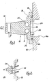
- the force sensor device firstly comprises a beam or profile, generally indicated at 10, which is capable of receiving a force F or a Cz couple at its free end 12.
- the opposite end of the beam 10 is in the form of a unitary rigid base 14.
- the base 14 is intended for fixing the element for example on the wall 16 of a conduit conveying an aggressive fluid. This fixing can be ensured using appropriate bolts (not shown).
- the beam 10 will preferably be made of a metal having good elasticity characteristics and resistant to aggressive fluid medium.
- a circular groove 18 which receives an O-ring 20. This thus ensures sealing between the fluid medium and the region, thus isolated from said medium, in which will take place, as described below, the measurement of a force and / or of a torque acting on the free end 12 of the beam 10.
- the wall 16 has in the region of the above-mentioned attachment an opening 16a.
- a part of the vertical end face of the element 10 is thus released, and this part is, in the present example, hollowed out to the same dimension as said opening 16a.
- the bottom 22 of the hollowed-out part, isolated from the fluid medium, acts as a measurement plane in which the measurement of the force and / or of the torque will take place.
- two sensor elements (28, 30) operating on a resistive principle, of the conventional strain gauge type will be fixed to the bottom of the hollowed-out part. These elements are not subjected to the action of the fluid, their lifespan can be extremely long, while retaining a traditional design.
- the high rigidity of the element 10 in torsion gives it a very small transverse deformation (perpendicular to the plane of the drawing). This avoids the vibrational phenomena of flexion / torsion coupling.
- the shape of the element is such that it has a very high rigidity with respect to forces or couples exerted in directions perpendicular to that of the force or torque measured.
- the shape of the element 10 as defined allows a significant rate of deformability in the direction of the force measured, to the benefit of sensitivity.
- the invention advantageously makes it possible to carry out force and / or torque measurements in an aggressive fluid medium by transferring the stresses to a region completely isolated from said medium, and by placing strain gauges according to an appropriate arrangement in this region. isolated.
- the measurement disturbances due to temperature and pressure differences in the medium, which are inevitable with the measurement devices of the prior art, are eliminated.
- the present invention is not limited to the embodiment described, but includes within its scope any variant or modification that may be made by those skilled in the art.
- shapes, dimensions, materials, etc. used for the elements can be very diverse.
Landscapes
- Physics & Mathematics (AREA)
- General Physics & Mathematics (AREA)
- Fluid Mechanics (AREA)
- Measurement Of Force In General (AREA)
- Force Measurement Appropriate To Specific Purposes (AREA)
- Measurement Of Length, Angles, Or The Like Using Electric Or Magnetic Means (AREA)
Claims (4)
Priority Applications (4)
| Application Number | Priority Date | Filing Date | Title |
|---|---|---|---|
| FR8511218A FR2585469B1 (fr) | 1985-07-23 | 1985-07-23 | Dispositif a jauges d'extensometrie pour la mesure d'efforts et/ou de couples |
| DE1986402245 DE263219T1 (de) | 1986-10-10 | 1986-10-10 | Vorrichtung mit dehnungsmessstreifen zur messung von kraeften und kopplungen. |
| DE8686402245T DE3669776D1 (de) | 1986-10-10 | 1986-10-10 | Vorrichtung mit dehnungsmessstreifen zur messung von kraeften und kopplungen. |
| EP19860402245 EP0263219B1 (de) | 1986-10-10 | 1986-10-10 | Vorrichtung mit Dehnungsmessstreifen zur Messung von Kräften und Kopplungen |
Applications Claiming Priority (1)
| Application Number | Priority Date | Filing Date | Title |
|---|---|---|---|
| EP19860402245 EP0263219B1 (de) | 1986-10-10 | 1986-10-10 | Vorrichtung mit Dehnungsmessstreifen zur Messung von Kräften und Kopplungen |
Publications (2)
| Publication Number | Publication Date |
|---|---|
| EP0263219A1 EP0263219A1 (de) | 1988-04-13 |
| EP0263219B1 true EP0263219B1 (de) | 1990-03-21 |
Family
ID=8196344
Family Applications (1)
| Application Number | Title | Priority Date | Filing Date |
|---|---|---|---|
| EP19860402245 Expired - Lifetime EP0263219B1 (de) | 1985-07-23 | 1986-10-10 | Vorrichtung mit Dehnungsmessstreifen zur Messung von Kräften und Kopplungen |
Country Status (2)
| Country | Link |
|---|---|
| EP (1) | EP0263219B1 (de) |
| DE (2) | DE263219T1 (de) |
Family Cites Families (2)
| Publication number | Priority date | Publication date | Assignee | Title |
|---|---|---|---|---|
| US3354716A (en) * | 1964-09-17 | 1967-11-28 | William S Hansen | Combined rate of flow, pressure and temperature gage |
| FR2485724A1 (fr) * | 1980-06-25 | 1981-12-31 | Commissariat Energie Atomique | Dispositif de mesure du debit d'un fluide circulant dans une canalisation |
-
1986
- 1986-10-10 EP EP19860402245 patent/EP0263219B1/de not_active Expired - Lifetime
- 1986-10-10 DE DE1986402245 patent/DE263219T1/de active Pending
- 1986-10-10 DE DE8686402245T patent/DE3669776D1/de not_active Expired - Fee Related
Also Published As
| Publication number | Publication date |
|---|---|
| DE3669776D1 (de) | 1990-04-26 |
| EP0263219A1 (de) | 1988-04-13 |
| DE263219T1 (de) | 1990-03-01 |
Similar Documents
| Publication | Publication Date | Title |
|---|---|---|
| US7171857B2 (en) | Pressure transducer | |
| KR960015060B1 (ko) | 선회형빔 와동센서 | |
| EP0291393B1 (de) | Struktur einer kapazitiven Zelle zum Messen von Differenzdrücken | |
| EP0634624B1 (de) | Gerät zum Messen einer Klemmkraft, die durch eine bewegbare Stange einer Längenmessvorrichtung ausgeübt wird | |
| FR2492978A1 (fr) | Capteur de pression capacitif | |
| FR2559899A1 (fr) | Detecteur de pression capacitif | |
| EP0410910B1 (de) | Membran-Deformationsmessvorrichtung | |
| WO2016193325A1 (fr) | Dispositif de detection de pression | |
| FR2619446A1 (fr) | Jauge de contrainte | |
| EP0506899B1 (de) | Vorrichtung zur messung der axialbelastungen eines schaftes | |
| FR2799837A1 (fr) | Procede et dispositif de mesure d'efforts en presence d'une pression exterieure | |
| FR2886403A1 (fr) | Collier de mesure de la deformation laterale d'une eprouvette lors d'essais de compression, notamment uniaxiale ou triaxiale | |
| WO2016174330A1 (fr) | Couplemètre à mesure de déformation | |
| EP3388808B1 (de) | Druckerfassungsvorrichtung mit mechanischer entkoppelung | |
| FR2605736A1 (fr) | Poutrelle de jauge de contrainte avec protection contre les surcharges incorporee | |
| EP0263219A1 (de) | Vorrichtung mit Dehnungsmessstreifen zur Messung von Kräften und Kopplungen | |
| EP0140780A2 (de) | Sonde zur Messung der lichten Weite eines Rohres sowie Verfahren zum Einführen der Sonde in dieses Rohr | |
| FR2585469A1 (fr) | Dispositif a jauges d'extensometrie pour la mesure d'efforts et/ou de couples | |
| FR2485724A1 (fr) | Dispositif de mesure du debit d'un fluide circulant dans une canalisation | |
| EP0720006A1 (de) | Verfahren und Vorrichtung zur nicht intrusiven Messung der Druckschwankungen einer Flüssigkeit innerhalb einer Kanalisation | |
| FR2845158A1 (fr) | Capteur de pression a reseau de bragg | |
| CA1309271C (fr) | Dispositif a jauges d'extensometrie pour la mesure d'efforts et/ou de couples | |
| EP0026682B1 (de) | Hydraulischer Kraftmesser | |
| FR3074292A1 (fr) | Dispositif de detection de pression a decouplage thermomecanique | |
| FR2473709A1 (fr) | Dispositif capteur de force et appareil de mesure equipe d'un tel dispositif |
Legal Events
| Date | Code | Title | Description |
|---|---|---|---|
| PUAI | Public reference made under article 153(3) epc to a published international application that has entered the european phase |
Free format text: ORIGINAL CODE: 0009012 |
|
| 17P | Request for examination filed |
Effective date: 19871019 |
|
| AK | Designated contracting states |
Kind code of ref document: A1 Designated state(s): BE CH DE GB IT LI LU NL |
|
| 17Q | First examination report despatched |
Effective date: 19880707 |
|
| GRAA | (expected) grant |
Free format text: ORIGINAL CODE: 0009210 |
|
| DET | De: translation of patent claims | ||
| AK | Designated contracting states |
Kind code of ref document: B1 Designated state(s): BE CH DE GB IT LI LU NL |
|
| ITF | It: translation for a ep patent filed | ||
| REF | Corresponds to: |
Ref document number: 3669776 Country of ref document: DE Date of ref document: 19900426 |
|
| GBT | Gb: translation of ep patent filed (gb section 77(6)(a)/1977) | ||
| PLBE | No opposition filed within time limit |
Free format text: ORIGINAL CODE: 0009261 |
|
| STAA | Information on the status of an ep patent application or granted ep patent |
Free format text: STATUS: NO OPPOSITION FILED WITHIN TIME LIMIT |
|
| 26N | No opposition filed | ||
| ITTA | It: last paid annual fee | ||
| EPTA | Lu: last paid annual fee | ||
| PGFP | Annual fee paid to national office [announced via postgrant information from national office to epo] |
Ref country code: NL Payment date: 20010927 Year of fee payment: 16 Ref country code: BE Payment date: 20010927 Year of fee payment: 16 |
|
| PGFP | Annual fee paid to national office [announced via postgrant information from national office to epo] |
Ref country code: GB Payment date: 20010928 Year of fee payment: 16 |
|
| PGFP | Annual fee paid to national office [announced via postgrant information from national office to epo] |
Ref country code: CH Payment date: 20011001 Year of fee payment: 16 |
|
| PGFP | Annual fee paid to national office [announced via postgrant information from national office to epo] |
Ref country code: DE Payment date: 20011004 Year of fee payment: 16 |
|
| PGFP | Annual fee paid to national office [announced via postgrant information from national office to epo] |
Ref country code: LU Payment date: 20011204 Year of fee payment: 16 |
|
| REG | Reference to a national code |
Ref country code: GB Ref legal event code: IF02 |
|
| PG25 | Lapsed in a contracting state [announced via postgrant information from national office to epo] |
Ref country code: LU Free format text: LAPSE BECAUSE OF NON-PAYMENT OF DUE FEES Effective date: 20021010 Ref country code: GB Free format text: LAPSE BECAUSE OF NON-PAYMENT OF DUE FEES Effective date: 20021010 |
|
| PG25 | Lapsed in a contracting state [announced via postgrant information from national office to epo] |
Ref country code: LI Free format text: LAPSE BECAUSE OF NON-PAYMENT OF DUE FEES Effective date: 20021031 Ref country code: CH Free format text: LAPSE BECAUSE OF NON-PAYMENT OF DUE FEES Effective date: 20021031 Ref country code: BE Free format text: LAPSE BECAUSE OF NON-PAYMENT OF DUE FEES Effective date: 20021031 |
|
| BERE | Be: lapsed |
Owner name: *SAPPEL Effective date: 20021031 |
|
| PG25 | Lapsed in a contracting state [announced via postgrant information from national office to epo] |
Ref country code: NL Free format text: LAPSE BECAUSE OF NON-PAYMENT OF DUE FEES Effective date: 20030501 Ref country code: DE Free format text: LAPSE BECAUSE OF NON-PAYMENT OF DUE FEES Effective date: 20030501 |
|
| GBPC | Gb: european patent ceased through non-payment of renewal fee |
Effective date: 20021010 |
|
| REG | Reference to a national code |
Ref country code: CH Ref legal event code: PL |
|
| NLV4 | Nl: lapsed or anulled due to non-payment of the annual fee |
Effective date: 20030501 |
|
| PG25 | Lapsed in a contracting state [announced via postgrant information from national office to epo] |
Ref country code: IT Free format text: LAPSE BECAUSE OF NON-PAYMENT OF DUE FEES Effective date: 20051010 |