EP0263260A1 - Torsiomètre coaxial - Google Patents
Torsiomètre coaxial Download PDFInfo
- Publication number
- EP0263260A1 EP0263260A1 EP87111460A EP87111460A EP0263260A1 EP 0263260 A1 EP0263260 A1 EP 0263260A1 EP 87111460 A EP87111460 A EP 87111460A EP 87111460 A EP87111460 A EP 87111460A EP 0263260 A1 EP0263260 A1 EP 0263260A1
- Authority
- EP
- European Patent Office
- Prior art keywords
- torque sensor
- windings
- primary
- strips
- shaft axis
- Prior art date
- Legal status (The legal status is an assumption and is not a legal conclusion. Google has not performed a legal analysis and makes no representation as to the accuracy of the status listed.)
- Withdrawn
Links
Images
Classifications
-
- G—PHYSICS
- G01—MEASURING; TESTING
- G01L—MEASURING FORCE, STRESS, TORQUE, WORK, MECHANICAL POWER, MECHANICAL EFFICIENCY, OR FLUID PRESSURE
- G01L3/00—Measuring torque, work, mechanical power, or mechanical efficiency, in general
- G01L3/02—Rotary-transmission dynamometers
- G01L3/04—Rotary-transmission dynamometers wherein the torque-transmitting element comprises a torsionally-flexible shaft
- G01L3/10—Rotary-transmission dynamometers wherein the torque-transmitting element comprises a torsionally-flexible shaft involving electric or magnetic means for indicating
- G01L3/101—Rotary-transmission dynamometers wherein the torque-transmitting element comprises a torsionally-flexible shaft involving electric or magnetic means for indicating involving magnetic or electromagnetic means
- G01L3/102—Rotary-transmission dynamometers wherein the torque-transmitting element comprises a torsionally-flexible shaft involving electric or magnetic means for indicating involving magnetic or electromagnetic means involving magnetostrictive means
Definitions
- the invention relates to a coaxial torque sensor, in which at least two strips of soft magnetic material are wound side by side around the circumference of a shaft, in which the strips each have a soft magnetic preferred direction, which run in opposite directions at an angle between 0 and 90 ° to the shaft axis and in which the strips are surrounded by at least one primary winding and one secondary winding each.
- Torque sensors of this type are known, for example, from the journal IEEE TRANSACTIONS ON MAGNETICS, Vol. Mag. 20, September 1984, pages 942 to 947 and 951 to 953.
- strips of amorphous material are glued to the circumference of the shaft at a distance from one another and at an angle of 45 ° to a shaft axis.
- the shaft is concentrically surrounded by an excitation coil and two secondary coils.
- the voltages generated in the secondary coils can be compared and evaluated, for example, in a bridge circuit. This creates a signal that is largely proportional to the torque to which the shaft in question is exposed.
- This signal is torque dependent because it causes the shaft and the associated stripes to deform and because the magnetic properties of such ferromagnetic materials change when subjected to mechanical stress.
- a magnetoelastic torque transmitter in which a measuring sleeve is applied to a shaft, which have parallel slots in two parallel, annular zones at different angles to the shaft axis. These zones of the measuring sleeves have a magnetic preferred direction, which cause different voltage states and thus different magnetic behavior due to a torque acting in the shaft.
- each magnetic zone is surrounded by a secondary winding and each secondary winding is in turn surrounded by a primary winding.
- the object of the present invention is to provide an arrangement in which falsification of the measurement signal is largely prevented by a displacement of the shaft within the windings surrounding it.
- width of the strips in the direction of the shaft axis is at least twice as large as the width of the associated secondary windings in the same direction, and that the secondary windings are adjusted so that they surround the central part of the associated strip.
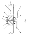
- a shaft 1 with the shaft axis 2 is surrounded by two strips 3 and 4. These strips are made of soft magnetic - preferably amorphous - material and have a preferred magnetic direction, which is indicated by the direction of hatching within strips 3 and 4 and which preferably extends at an angle of 45 ° to the direction of shaft axis 2. It is surrounded Shaft 1 from a bobbin 5, which - seen in the direction of the shaft axis 2 - carries two secondary windings 6 and 7 on the outside and a primary winding 8 in the middle. The primary winding 8 is connected to an AC voltage source 9 and the secondary windings are connected in series with one another and connected to measuring terminals 10 at which the output signal is present.
- the arrangement of primary and secondary windings means that the secondary windings 6 and 7 need only have a small width in the direction of the shaft axis 2, so that the ratio of the width of the strips 3 and 4 to the width of the windings 6 and 7 is slightly relative can be made big.
- the arrangement of the primary winding 8 in the direction of the shaft axis 2 next to - here between - the secondary windings 6 and 7 gives the advantage that - regardless of the outer diameter of the secondary windings - the primary winding is close to the shaft 1, so that the lowest possible energy is necessary to ensure sufficient flooding of strips 3 and 4.
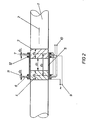
- the embodiment of Figure 2 has the advantage over the arrangement of Figure 1 that the magnetic circuits of the secondary windings 6 and 7 are largely decoupled from each other by the distance d3 of the secondary windings 6 and 7 and strips 3 and 4.
- the width d4 of strips 3 and 4 is again large the corresponding width of the secondary windings 6 and 7.
- the inner spacing of the strips 3 and 4 from each other is denoted by d 1 and should be greater, the more soft magnetic the material of the shaft 1 is.
- the shaft 1 moves relative to the bobbin 5 in the direction of the shaft axis 2, not only will the secondary windings remain largely in the central region of the strips 3 and 4, but also that produced by the primary winding 11 and that by the primary winding 12 Magnetic field influenced by the displacement in the same sense, so that there is a reduced sensitivity of the torque sensor to displacements of the shaft 1 and the bobbin 5 compared to the embodiment of Figure 1.
- a further reduction in sensitivity to displacements of the shaft 1 can be achieved by shielding the coil body 5 at the end, since these limit the expansion of the magnetic field generated by the primary windings in the direction of the shaft axis and thus reduce the influence of the outer edges of the strips 3 and 4 .
Landscapes
- Physics & Mathematics (AREA)
- Electromagnetism (AREA)
- General Physics & Mathematics (AREA)
- Transmission And Conversion Of Sensor Element Output (AREA)
- Measurement Of Length, Angles, Or The Like Using Electric Or Magnetic Means (AREA)
Applications Claiming Priority (2)
| Application Number | Priority Date | Filing Date | Title |
|---|---|---|---|
| DE19863629610 DE3629610A1 (de) | 1986-08-30 | 1986-08-30 | Koaxialer drehmomentsensor |
| DE3629610 | 1986-08-30 |
Publications (1)
| Publication Number | Publication Date |
|---|---|
| EP0263260A1 true EP0263260A1 (fr) | 1988-04-13 |
Family
ID=6308597
Family Applications (1)
| Application Number | Title | Priority Date | Filing Date |
|---|---|---|---|
| EP87111460A Withdrawn EP0263260A1 (fr) | 1986-08-30 | 1987-08-07 | Torsiomètre coaxial |
Country Status (2)
| Country | Link |
|---|---|
| EP (1) | EP0263260A1 (fr) |
| DE (1) | DE3629610A1 (fr) |
Cited By (1)
| Publication number | Priority date | Publication date | Assignee | Title |
|---|---|---|---|---|
| DE19821381A1 (de) * | 1998-05-13 | 1999-07-22 | Bosch Gmbh Robert | Vorrichtung zur Erfassung von Drehmomenten |
Families Citing this family (2)
| Publication number | Priority date | Publication date | Assignee | Title |
|---|---|---|---|---|
| DE3918862A1 (de) * | 1989-06-09 | 1991-01-10 | Danfoss As | Drehmoment-messeinrichtung |
| DE102019112795A1 (de) * | 2019-05-15 | 2020-11-19 | Trafag Ag | Belastungsmessanordnung, Herstellverfahren hierfür und damit durchführbares Belastungsmessverfahren |
Citations (1)
| Publication number | Priority date | Publication date | Assignee | Title |
|---|---|---|---|---|
| DE3319449A1 (de) * | 1983-05-28 | 1984-11-29 | ASEA AB, Västeraas | Magnetoelastischer drehmomentgeber |
-
1986
- 1986-08-30 DE DE19863629610 patent/DE3629610A1/de not_active Withdrawn
-
1987
- 1987-08-07 EP EP87111460A patent/EP0263260A1/fr not_active Withdrawn
Patent Citations (1)
| Publication number | Priority date | Publication date | Assignee | Title |
|---|---|---|---|---|
| DE3319449A1 (de) * | 1983-05-28 | 1984-11-29 | ASEA AB, Västeraas | Magnetoelastischer drehmomentgeber |
Non-Patent Citations (1)
| Title |
|---|
| IEEE TRANSACTIONS ON MAGNETICS, Band MAG-20, Nr. 5, September 1984, Seiten 942-947; K. MOHRI "Review of recent advances in the field of amorphous-metal sensors and transducers"; Seiten 951-953; I. SASADA et al.: "Torque transducers with stress-sensitive amorphous ribbons of chevron-pattern" * |
Cited By (2)
| Publication number | Priority date | Publication date | Assignee | Title |
|---|---|---|---|---|
| DE19821381A1 (de) * | 1998-05-13 | 1999-07-22 | Bosch Gmbh Robert | Vorrichtung zur Erfassung von Drehmomenten |
| DE19821381C2 (de) * | 1998-05-13 | 2000-01-13 | Bosch Gmbh Robert | Vorrichtung zur Erfassung von Drehmomenten |
Also Published As
| Publication number | Publication date |
|---|---|
| DE3629610A1 (de) | 1988-03-03 |
Similar Documents
| Publication | Publication Date | Title |
|---|---|---|
| EP0393387B1 (fr) | Agencement de bobines pour un appareil de détection inductive | |
| EP0379492B1 (fr) | Dispositif de mesure de l'angle de rotation et/ou du couple | |
| DE69315665T2 (de) | Ein mechanischer Sensor | |
| DE68918549T2 (de) | Verschiebungsmessapparat. | |
| DE2449697A1 (de) | Mechano-elektrischer wandler | |
| DE69217241T2 (de) | Induktiver winkelverschiebungssensor | |
| DE3940220A1 (de) | Belastungsdetektor | |
| CH680391A5 (fr) | ||
| DE69019491T2 (de) | Verschiebungssensor vom Induktionstyp mit Unempfindlichkeit gegenüber externen magnetischen Feldern. | |
| DE3718857A1 (de) | Stromsensor nach dem kompensationsprinzip | |
| DE10027095B4 (de) | Drehmomentdetektoranordnung | |
| CH406666A (de) | Anordnung zum Messen von Zug- oder Druckspannungen in einem Messobjekt aus magnetostriktivem Material | |
| DE3517849C2 (fr) | ||
| DE69312138T2 (de) | Messgeber | |
| DE2117266A1 (de) | Magnetometer | |
| EP0263260A1 (fr) | Torsiomètre coaxial | |
| EP0806674B1 (fr) | Capteur de courant à compensation du courant | |
| EP0512282B1 (fr) | Capteur d'angle pour déterminer sans contact la rotation d'un arbre | |
| DE3218508C2 (de) | Frequenzgespeiste Meßspulenanordnung für einen induktiven Drehwinkelaufnehmer | |
| DE3241018A1 (de) | Magnetisch arbeitender sensor | |
| DE102022111747A1 (de) | Differenzstromsensor für hohe Ströme | |
| DE3919749C2 (fr) | ||
| DE4211614A1 (de) | Meßeinrichtung zur Bestimmung eines Drehwinkels | |
| EP0559943B1 (fr) | Capteur donnant un signal de position | |
| EP0342509B1 (fr) | Générateur d'impulsion d'angle |
Legal Events
| Date | Code | Title | Description |
|---|---|---|---|
| PUAI | Public reference made under article 153(3) epc to a published international application that has entered the european phase |
Free format text: ORIGINAL CODE: 0009012 |
|
| AK | Designated contracting states |
Kind code of ref document: A1 Designated state(s): AT DE FR GB IT SE |
|
| 17P | Request for examination filed |
Effective date: 19880316 |
|
| 17Q | First examination report despatched |
Effective date: 19890116 |
|
| STAA | Information on the status of an ep patent application or granted ep patent |
Free format text: STATUS: THE APPLICATION HAS BEEN WITHDRAWN |
|
| 18W | Application withdrawn |
Withdrawal date: 19890518 |
|
| R18W | Application withdrawn (corrected) |
Effective date: 19890518 |
|
| RIN1 | Information on inventor provided before grant (corrected) |
Inventor name: ERB, OTTO, DR. |