EP0263283A2 - Bogie pour véhicule ferroviaire - Google Patents
Bogie pour véhicule ferroviaire Download PDFInfo
- Publication number
- EP0263283A2 EP0263283A2 EP87112224A EP87112224A EP0263283A2 EP 0263283 A2 EP0263283 A2 EP 0263283A2 EP 87112224 A EP87112224 A EP 87112224A EP 87112224 A EP87112224 A EP 87112224A EP 0263283 A2 EP0263283 A2 EP 0263283A2
- Authority
- EP
- European Patent Office
- Prior art keywords
- bogie
- steering device
- preferably according
- wheel sets
- angle
- Prior art date
- Legal status (The legal status is an assumption and is not a legal conclusion. Google has not performed a legal analysis and makes no representation as to the accuracy of the status listed.)
- Granted
Links
Images


Classifications
-
- B—PERFORMING OPERATIONS; TRANSPORTING
- B61—RAILWAYS
- B61F—RAIL VEHICLE SUSPENSIONS, e.g. UNDERFRAMES, BOGIES OR ARRANGEMENTS OF WHEEL AXLES; RAIL VEHICLES FOR USE ON TRACKS OF DIFFERENT WIDTH; PREVENTING DERAILING OF RAIL VEHICLES; WHEEL GUARDS, OBSTRUCTION REMOVERS OR THE LIKE FOR RAIL VEHICLES
- B61F5/00—Constructional details of bogies; Connections between bogies and vehicle underframes; Arrangements or devices for adjusting or allowing self-adjustment of wheel axles or bogies when rounding curves
- B61F5/38—Arrangements or devices for adjusting or allowing self- adjustment of wheel axles or bogies when rounding curves, e.g. sliding axles, swinging axles
- B61F5/44—Adjustment controlled by movements of vehicle body
Definitions
- the present invention relates to a bogie for a rail vehicle with at least two wheel sets and at least one passive steering device, which each pivotably connects two wheel sets to one another and has a third control lever provided with a pivot point for pivotably connecting to a car body, and a rail vehicle.
- DE-PS 31 19 164 As an active steering device in the prior art, the embodiment shown in DE-PS 31 19 164 is known, the horizontally arranged linkage of which is actuated in normal operation by means of a piston-cylinder unit via a control unit, which receives its impulse from an encoder which does this Game of the flange of a wheel to the inside edge of the rail detected.
- Passive steering devices derive their adjustment movement directly from the turning angle, which is only available in sufficient size when cornering through the car body moving relative to the bogie.
- CH-PS 183 368 has already attempted to create a steering device which is arranged horizontally between the body and the bogie and uses its relative turning movement.
- the articulation point of the car body is on the inside, i.e. its distance from the common longitudinal median plane of the car body / bogie is smaller than the corresponding distance of the bogie-side fixed point by which the rod is unscrewed.
- CH-PS 644 806 Another, also horizontally arranged steering device is shown in CH-PS 644 806, which has an internal articulation point of the car body with respect to the bogie-side fixed point. Otherwise, this version is extremely complex in that an attempt is made to generate a non-linear lever movement for the steering of the wheel sets by means of a four-bar linkage and correspondingly increased pivot points. This is intended to achieve stable vehicle running on straight sections and progressively increasing leverage with increasing section curvature.
- the present invention has for its object to provide a bogie with a passive steering device for rail vehicles, especially for vehicles with small radii, such as trams and light rail vehicles, with at least one steering device being arranged approximately horizontally between the bogie and car body, and their relative turning movements be used as an adjustment variable for the wheel set control so that the rubber-elastic elements used in the pivot and articulation points of the steering device sought are optimal in terms of their angle of rotation.
- leading and trailing wheelsets of a bogie should m.W. are forcibly aligned with the center of the curve due to the relative unscrewing movement between the car body and the bogie due to cornering by means of at least one, preferably horizontally arranged linkage.
- the invention solves this problem according to the wording of claim 1 by, because of its special arrangement, it offers the known advantages of a steering device (avoidance of sheet running noise, longer service life of the wheel sets) and at the same time the to date has been able to prevent disadvantages associated with the use of such devices (high wear in the pivot points).
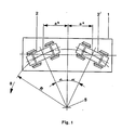
- a bogie 2, 2 ⁇ is pivoted under a car body 1 by a turning angle ⁇ depending on a curve radius R and a pivot distance 2a *.
- ⁇ arc sin .
- the ratio of the setting angle ⁇ to the turning angle ⁇ finally forms a transmission ratio G, known as "passive steering gain", for the carriage-side forced control of the wheel sets of a bogie by means of a passive steering device.
- G the transmission ratio
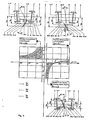
- Fig. 3 the known from the prior art, horizontal steering devices passive type 10, 20 and their effects in relation to an angle of rotation ⁇ of the rubber-elastic elements 9 provided at all pivot and hinge points are compared to a steering device 30 according to the invention.
- a steering device 30 for the better overview, only one bogie side with steering device is shown, because of the steering devices arranged on both sides of a longitudinal center plane 4 on a bogie 2, 2 ⁇ in mirror image.
- a passive steering device 10 mentioned at the beginning of the prior art is shown, which is arranged horizontally in a bogie 2, 2 ⁇ and has an “inner” articulation point 11 of the body 1.
- “inside” is the relation of a distance b5 of the articulation point 11 compared to a distance b4 of a fixed point 13, around which the turning out of the steering device 10 takes place, to its common longitudinal center plane 4.
- the relationship is: b5 ⁇ b4.
- the steering device 10 shown consists of an inwardly directed control lever 12 which does not protrude beyond the longitudinal center plane 4 and which is rotatably mounted on the bogie 2, 2 ⁇ in a fixed point 13 on the one hand and on the other hand has the two pivot points 14, 15, one of which is longitudinal Control rod 16, 17 connects to the hinge points 18, 19 of the two wheel sets 3, 3 instruments.
- the ratio of the distances includes the relation of a distance b1 or b2 of the associated hinge point 18 or 19, as the point of application of the control rod 16 or 17 in question on the respective wheel set 3 or 3 ⁇ , compared to a distance b5 of the inner articulation point 11 to their common longitudinal median plane 4.
- Das relationship describes the relation of a distance b4 of a fixed point 13 on the bogie 2, 2 ⁇ , around which the turning out of the steering device 10 takes place, compared to a distance b5 of an internal articulation point 11, to the common longitudinal center plane 4 thereof.
- a passive steering device 20 mentioned at the beginning of the prior art is shown, which is arranged horizontally in a bogie 2, 2 ⁇ and has an “outside” articulation point 21 of the car body 1.
- "Outside” is the relation of a distance b5 of the articulation point 21 to a distance b4 of a fixed point 23 on the bogie 2, 2 ⁇ , around which the turning-out movement of the steering device 20 takes place, referred to its common longitudinal center plane 4.
- the relationship is: b5> b4.
- the steering device 20 shown consists of an outwardly directed control lever 22, which on the one hand is rotatably mounted on the bogie 2, 2 ⁇ in a fixed point 23 and on the other hand has the two pivot points 24, 25, each of which has a longitudinal control rod 26, 27 to connect the hinge points 28, 29 of the two wheel sets 3, 3 ⁇ .
- the effect of a steering device 20 with an external articulation point 21 with respect to the angle of rotation ⁇ of the rubber-elastic elements 9 provided in all pivot points is visible in a graphical representation, which shows the angle of rotation ⁇ of the rubber-elastic elements 9 as a function of those values which result from the ratio of the distances or surrender.
- the ratio of the distances includes the relation of a distance b1 or b2 of the associated articulation point 28 or 29, as the point of application of the control rod 26 or 27 in question on the respective wheel set 3 or 3 ⁇ , compared to a distance b5 of the outer articulation point 21 to their common Longitudinal median plane 4.
- the ratio describes the relation of a distance b4 of a fixed point 23 on the bogie 2, 2 ⁇ , around which the turning movement of the steering device 20 takes place, with respect to a distance b5 an external articulation point 21, to the common longitudinal median plane 4.
- a comparative analysis of the effect of a steering device 10 with an internal articulation point 11 compared to a steering device 20 with an external articulation point 21 shows clear disadvantages for the latter type in relation to the twist angle ⁇ of the rubber-elastic elements 9.
- a passive steering device 30 which is arranged horizontally in a bogie 2, 2 ⁇ and has an “internal negative” articulation point 31 of the body 1, such that the articulation point 31 extends over the longitudinal center plane 4 protrudes.
- the term “internally negative” denotes the relation of a distance -b5 of the articulation point 31 to a distance b4 of a fixed point 33 on the bogie 2, 2 ⁇ , around which the turning-out movement of the steering device 30 takes place, to its common longitudinal center plane 4.
- the relationship is: -b5 ⁇ o.
- the steering device 30 consists of an inwardly directed, beyond the longitudinal center plane 4 control lever 32, which is rotatably mounted on the one hand on the bogie 2, 2 Vietnamese in a fixed point 33 and on the other hand has the two pivot points 34, 35, each of which has a longitudinal control rod 36, 37 establishes the connection to the articulation points 38, 39 of the two wheel sets 3, 3 ⁇ .
- the effect of a steering device 30 according to the invention with an internal, negative articulation point 31 with respect to the angle of rotation ⁇ of the rubber-elastic elements 9 provided in all pivot points is visible in a graphical representation, which shows the angle of rotation ⁇ of the rubber-elastic elements 9 as a function of the values that result from them the ratio of the distances surrender.
- the ratio of the distances includes the relation of a distance b1 or b2 of the associated hinge point 38 or 39, as the point of application of the control rod 36 or 37 in question on the respective wheel set 3 or 3 ⁇ , with respect to a distance -b5 of the inner, negative articulation point 31 to their common longitudinal median plane 4 .
- the relationship describes the relation of a distance b44 of a fixed point 33 on the bogie 2,2 ⁇ , around which the turning out of the steering device 30 takes place, compared to a distance -b5 of an internal, negative articulation point 31 to its common longitudinal center plane 4.
- a comparative consideration of the effect of a steering device 20 with an external articulation point 21 compared to a steering device 30 according to the invention with an internal, negative articulation point 31 shows clear advantages for the design according to the invention in relation to the angle of rotation ⁇ of the rubber-elastic elements 9. These result from the fact that the angle of rotation ⁇ , as can be shown mathematically, always assumes a value that is greater than the angle of rotation ⁇ of a bogie 2.2 ⁇ under a car body 1 when cornering.
- a comparative examination of the effect of a steering device 10 with an internal articulation point 11 compared to a steering device 30 according to the invention with an internal, negative articulation point 31 also shows advantages for the design according to the invention in relation to the angle of rotation ⁇ of the rubber-elastic elements 9. These are clearly visible through the position of the area N in the coordinate system or its three limit curves. With one of the ratios described above as the input variable, the effective rotation angle ⁇ for the rubber-elastic elements 9 of each pivot point of a steering device 30 according to the invention can be immediately compared to that of a steering device 20.
- the steering device 30 according to the invention with an internal, negative articulation point 31 fulfills a long-standing, unsatisfied need, in that, due to its special arrangement, it offers the advantages of a steering device known per se (avoidance of arc running noise and longer service life of the wheel sets) and at the same time that with disadvantages associated with the use of such devices (high wear in the pivot points) is able to prevent.
- the two bogies 2, 2 ' are pivoted in a known manner relative to the car body 1, seen in plan view, in the opposite direction of rotation about their vertical axis of rotation.
- the bogie 2 is pivoted counterclockwise by a deflection angle ⁇ and the bogie 2 ⁇ by the same deflection angle ⁇ clockwise in a left curve, whereby a horizontal between car body 1 by the articulation point 31 visible in FIG. 4 and bogie 2.2 ⁇ arranged steering device 30 is put into action.
- the control lever 32 which is rotatably mounted on the bogie 2, 2 'at a fixed point 33, rotates counterclockwise by the setting angle ⁇ and actuates the two longitudinal control rods 36, 37 each in tension.
- the radial setting of the two wheel sets 3, 3 ⁇ is in each case carried out by the setting angle ⁇ , the wheel set 3 being aligned counterclockwise and the wheel set 3 ⁇ clockwise toward the center of the curve 5.
- the relationship exists with respect to the angular relationships in the shown steering device 30 with an internal, negative articulation point: ⁇ ⁇ ⁇ .
- a passive steering device 30 shown in FIG. 4 with an internal, negative articulation point 31 is preferably suitable for use with bogies which enable the radial setting of the wheel sets by means of two articulated half frames.
- two steering devices 30 In a bogie with a conventional bogie frame, two steering devices 30 must be arranged in mirror images on both sides of a longitudinal center plane 4 for each bogie for the forced radial adjustment of the wheel sets, whereby the relative movements of the radially adjusting wheel sets can be accommodated in the wheel set guide or primary suspension.
- the steering device according to the invention acts on the leading and trailing wheel sets of a bogie.
Landscapes
- Engineering & Computer Science (AREA)
- Mechanical Engineering (AREA)
- Vehicle Body Suspensions (AREA)
- Braking Arrangements (AREA)
- Ceramic Products (AREA)
- Platform Screen Doors And Railroad Systems (AREA)
- Carriers, Traveling Bodies, And Overhead Traveling Cranes (AREA)
- Body Structure For Vehicles (AREA)
Priority Applications (1)
| Application Number | Priority Date | Filing Date | Title |
|---|---|---|---|
| AT87112224T ATE60555T1 (de) | 1986-09-30 | 1987-08-22 | Drehgestell und schienenfahrzeug. |
Applications Claiming Priority (2)
| Application Number | Priority Date | Filing Date | Title |
|---|---|---|---|
| CH3906/86A CH671931A5 (fr) | 1986-09-30 | 1986-09-30 | |
| CH3906/86 | 1986-09-30 |
Publications (3)
| Publication Number | Publication Date |
|---|---|
| EP0263283A2 true EP0263283A2 (fr) | 1988-04-13 |
| EP0263283A3 EP0263283A3 (en) | 1988-06-08 |
| EP0263283B1 EP0263283B1 (fr) | 1991-01-30 |
Family
ID=4266044
Family Applications (1)
| Application Number | Title | Priority Date | Filing Date |
|---|---|---|---|
| EP87112224A Expired - Lifetime EP0263283B1 (fr) | 1986-09-30 | 1987-08-22 | Bogie pour véhicule ferroviaire |
Country Status (4)
| Country | Link |
|---|---|
| EP (1) | EP0263283B1 (fr) |
| AT (1) | ATE60555T1 (fr) |
| CH (1) | CH671931A5 (fr) |
| DE (1) | DE3767820D1 (fr) |
Cited By (1)
| Publication number | Priority date | Publication date | Assignee | Title |
|---|---|---|---|---|
| DE19505338A1 (de) * | 1995-02-17 | 1995-07-20 | Sig Schweiz Industrieges | Lenkmechanismus zur kurvenradialen Steuerung der Radsätze von Fahrwerken bei Schienenfahrzeugen |
Families Citing this family (2)
| Publication number | Priority date | Publication date | Assignee | Title |
|---|---|---|---|---|
| AT398060B (de) * | 1990-02-22 | 1994-09-26 | Sgp Verkehrstechnik | Radsatzsteuerung für ein triebdrehgestell eines schienenfahrzeuges |
| DE4419878C1 (de) * | 1994-06-07 | 1995-07-20 | Sig Schweiz Industrieges | In axialer Richtung bewegliche Achsanordnung für Schienenfahrzeuge |
Family Cites Families (3)
| Publication number | Priority date | Publication date | Assignee | Title |
|---|---|---|---|---|
| CH204678A (de) * | 1938-05-03 | 1939-05-15 | Sig Schweiz Industrieges | Motordrehgestell an Schienenfahrzeugen, mit zwangsläufig radial sich einstellenden Achslenkgestellen. |
| BE639836A (fr) * | 1962-11-13 | |||
| US4542699A (en) * | 1983-11-25 | 1985-09-24 | Urban Transportation Development Corporation Ltd. | Powered radial truck |
-
1986
- 1986-09-30 CH CH3906/86A patent/CH671931A5/de not_active IP Right Cessation
-
1987
- 1987-08-22 AT AT87112224T patent/ATE60555T1/de not_active IP Right Cessation
- 1987-08-22 EP EP87112224A patent/EP0263283B1/fr not_active Expired - Lifetime
- 1987-08-22 DE DE8787112224T patent/DE3767820D1/de not_active Expired - Fee Related
Cited By (1)
| Publication number | Priority date | Publication date | Assignee | Title |
|---|---|---|---|---|
| DE19505338A1 (de) * | 1995-02-17 | 1995-07-20 | Sig Schweiz Industrieges | Lenkmechanismus zur kurvenradialen Steuerung der Radsätze von Fahrwerken bei Schienenfahrzeugen |
Also Published As
| Publication number | Publication date |
|---|---|
| ATE60555T1 (de) | 1991-02-15 |
| EP0263283B1 (fr) | 1991-01-30 |
| EP0263283A3 (en) | 1988-06-08 |
| DE3767820D1 (de) | 1991-03-07 |
| CH671931A5 (fr) | 1989-10-13 |
Similar Documents
| Publication | Publication Date | Title |
|---|---|---|
| DE2660079C3 (de) | Verstelleinrichtung für einen Schienenfahrzeug-Radsatz in einem zwei- oder mehrachsigen Drehgestell | |
| DE1605826C3 (de) | Drehgestell für Eisenbahnwagen mit mindestens zwei Radsätzen | |
| DE69504667T2 (de) | Kupplungsvorrichtung zur kontrolle des winkelversetzes zwischen zwei wegtransporteinheiten die miteinander verbunden sind durch eine selbsttragende zwischeneinheit | |
| DE4140126C2 (de) | Laufwerk für Schienenfahrzeuge | |
| DD287446A5 (de) | Drehgestell fuer schnellfahrende schienenfahrzeuge | |
| CH671195A5 (fr) | ||
| DE1605053A1 (de) | Schienenfahrzeug mit Drehgestell | |
| EP0273940B1 (fr) | Dispositif de stabilisation mecanique de vehicules roulant sur rails | |
| DE6932349U (de) | Gliederzuggarnitur. | |
| EP0263283A2 (fr) | Bogie pour véhicule ferroviaire | |
| EP1373048B1 (fr) | Bogie autoguide a trois essieux | |
| DE202009000688U1 (de) | Fahrzeug mit Wankstützen | |
| DE2929896C2 (de) | Vorrichtung zum Kuppeln zweier Drehgestelle eines Schienenfahrzeuges | |
| EP0679561B1 (fr) | Bogie auto-directeur à trois essieux avec poutres de direction | |
| AT359121B (de) | Schienenfahrzeug | |
| DE3119332C2 (de) | Drehgestell | |
| DE3723493A1 (de) | Vorrichtung zum lastabhaengigen regeln des bremsdruckes bei mehrachsfahrzeugen | |
| DE2012048C3 (de) | Schienengliederfahrzeug | |
| DE2536384A1 (de) | Lenkungssteuermechanismus | |
| DE2133339C3 (de) | Drehgestell für Schienenfahrzeuge, insbesondere für schnellfahrende Schienenfahrzeuge mit Verschleißprofil an den Radsätzen | |
| DE3876751T2 (de) | Lenkerverbindung fuer die laengssteuerung der achseninnenjoche von eisenbahndrehgestellen. | |
| DE2103100C3 (de) | Drehgestell für Schienenfahrzeuge, insbesondere für schnellfahrende Schienenfahrzeuge mit Verschleißprofil an den Radsätzen | |
| DE1926298C3 (de) | Drehgestell, insbesondere verwindungsweiches Drehgestell für Schienenfahrzeuge, vorzugsweise für Reisezugwagen | |
| CH690761A5 (de) | Achsanordnung. | |
| DE1655104B2 (de) | Vorrichtung zur Anlenkung eines als Achsträger dienenden Hilfsrahmens an der Karosserie oder dem Hauptrahmen eines Fahrzeugs |
Legal Events
| Date | Code | Title | Description |
|---|---|---|---|
| PUAI | Public reference made under article 153(3) epc to a published international application that has entered the european phase |
Free format text: ORIGINAL CODE: 0009012 |
|
| AK | Designated contracting states |
Kind code of ref document: A2 Designated state(s): AT BE DE FR GB IT NL SE |
|
| PUAL | Search report despatched |
Free format text: ORIGINAL CODE: 0009013 |
|
| AK | Designated contracting states |
Kind code of ref document: A3 Designated state(s): AT BE DE FR GB IT NL SE |
|
| 17P | Request for examination filed |
Effective date: 19880720 |
|
| 17Q | First examination report despatched |
Effective date: 19890712 |
|
| ITF | It: translation for a ep patent filed | ||
| GRAA | (expected) grant |
Free format text: ORIGINAL CODE: 0009210 |
|
| AK | Designated contracting states |
Kind code of ref document: B1 Designated state(s): AT BE DE FR GB IT NL SE |
|
| REF | Corresponds to: |
Ref document number: 60555 Country of ref document: AT Date of ref document: 19910215 Kind code of ref document: T |
|
| GBT | Gb: translation of ep patent filed (gb section 77(6)(a)/1977) | ||
| REF | Corresponds to: |
Ref document number: 3767820 Country of ref document: DE Date of ref document: 19910307 |
|
| ET | Fr: translation filed | ||
| PLBE | No opposition filed within time limit |
Free format text: ORIGINAL CODE: 0009261 |
|
| STAA | Information on the status of an ep patent application or granted ep patent |
Free format text: STATUS: NO OPPOSITION FILED WITHIN TIME LIMIT |
|
| 26N | No opposition filed | ||
| EAL | Se: european patent in force in sweden |
Ref document number: 87112224.8 |
|
| PGFP | Annual fee paid to national office [announced via postgrant information from national office to epo] |
Ref country code: GB Payment date: 19960813 Year of fee payment: 10 |
|
| PGFP | Annual fee paid to national office [announced via postgrant information from national office to epo] |
Ref country code: SE Payment date: 19960820 Year of fee payment: 10 |
|
| PGFP | Annual fee paid to national office [announced via postgrant information from national office to epo] |
Ref country code: DE Payment date: 19960821 Year of fee payment: 10 |
|
| PGFP | Annual fee paid to national office [announced via postgrant information from national office to epo] |
Ref country code: FR Payment date: 19960828 Year of fee payment: 10 |
|
| PGFP | Annual fee paid to national office [announced via postgrant information from national office to epo] |
Ref country code: AT Payment date: 19960829 Year of fee payment: 10 |
|
| PGFP | Annual fee paid to national office [announced via postgrant information from national office to epo] |
Ref country code: NL Payment date: 19960831 Year of fee payment: 10 |
|
| PGFP | Annual fee paid to national office [announced via postgrant information from national office to epo] |
Ref country code: BE Payment date: 19960923 Year of fee payment: 10 |
|
| PG25 | Lapsed in a contracting state [announced via postgrant information from national office to epo] |
Ref country code: GB Free format text: LAPSE BECAUSE OF NON-PAYMENT OF DUE FEES Effective date: 19970822 Ref country code: AT Free format text: LAPSE BECAUSE OF NON-PAYMENT OF DUE FEES Effective date: 19970822 |
|
| PG25 | Lapsed in a contracting state [announced via postgrant information from national office to epo] |
Ref country code: SE Free format text: LAPSE BECAUSE OF NON-PAYMENT OF DUE FEES Effective date: 19970823 |
|
| PG25 | Lapsed in a contracting state [announced via postgrant information from national office to epo] |
Ref country code: BE Free format text: LAPSE BECAUSE OF NON-PAYMENT OF DUE FEES Effective date: 19970831 |
|
| BERE | Be: lapsed |
Owner name: SIG SCHWEIZERISCHE INDUSTRIE-GESELLSCHAFT Effective date: 19970831 |
|
| PG25 | Lapsed in a contracting state [announced via postgrant information from national office to epo] |
Ref country code: NL Free format text: LAPSE BECAUSE OF NON-PAYMENT OF DUE FEES Effective date: 19980301 |
|
| GBPC | Gb: european patent ceased through non-payment of renewal fee |
Effective date: 19970822 |
|
| PG25 | Lapsed in a contracting state [announced via postgrant information from national office to epo] |
Ref country code: FR Free format text: LAPSE BECAUSE OF NON-PAYMENT OF DUE FEES Effective date: 19980430 |
|
| PG25 | Lapsed in a contracting state [announced via postgrant information from national office to epo] |
Ref country code: DE Free format text: LAPSE BECAUSE OF NON-PAYMENT OF DUE FEES Effective date: 19980501 |
|
| EUG | Se: european patent has lapsed |
Ref document number: 87112224.8 |
|
| NLV4 | Nl: lapsed or anulled due to non-payment of the annual fee |
Effective date: 19980301 |
|
| REG | Reference to a national code |
Ref country code: FR Ref legal event code: ST |
|
| PG25 | Lapsed in a contracting state [announced via postgrant information from national office to epo] |
Ref country code: IT Free format text: LAPSE BECAUSE OF NON-PAYMENT OF DUE FEES Effective date: 20050822 |