EP0263389A1 - Dispositif avec au moins un cadre de guidage pour les paliers mobiles des broches des bobines pour bandes à enrouler - Google Patents
Dispositif avec au moins un cadre de guidage pour les paliers mobiles des broches des bobines pour bandes à enrouler Download PDFInfo
- Publication number
- EP0263389A1 EP0263389A1 EP87114116A EP87114116A EP0263389A1 EP 0263389 A1 EP0263389 A1 EP 0263389A1 EP 87114116 A EP87114116 A EP 87114116A EP 87114116 A EP87114116 A EP 87114116A EP 0263389 A1 EP0263389 A1 EP 0263389A1
- Authority
- EP
- European Patent Office
- Prior art keywords
- frame
- guide
- inner frame
- sliding bearings
- frames
- Prior art date
- Legal status (The legal status is an assumption and is not a legal conclusion. Google has not performed a legal analysis and makes no representation as to the accuracy of the status listed.)
- Granted
Links
- 238000004804 winding Methods 0.000 claims abstract description 162
- 239000000463 material Substances 0.000 claims abstract description 33
- 230000008878 coupling Effects 0.000 claims description 16
- 238000010168 coupling process Methods 0.000 claims description 16
- 238000005859 coupling reaction Methods 0.000 claims description 16
- 239000013072 incoming material Substances 0.000 description 8
- 238000006073 displacement reaction Methods 0.000 description 4
- 239000010410 layer Substances 0.000 description 4
- 239000012815 thermoplastic material Substances 0.000 description 3
- 239000004033 plastic Substances 0.000 description 2
- 230000001105 regulatory effect Effects 0.000 description 2
- RYGMFSIKBFXOCR-UHFFFAOYSA-N Copper Chemical compound [Cu] RYGMFSIKBFXOCR-UHFFFAOYSA-N 0.000 description 1
- 229910052782 aluminium Inorganic materials 0.000 description 1
- XAGFODPZIPBFFR-UHFFFAOYSA-N aluminium Chemical compound [Al] XAGFODPZIPBFFR-UHFFFAOYSA-N 0.000 description 1
- 239000002131 composite material Substances 0.000 description 1
- 229910052802 copper Inorganic materials 0.000 description 1
- 239000010949 copper Substances 0.000 description 1
- 230000001419 dependent effect Effects 0.000 description 1
- 239000011888 foil Substances 0.000 description 1
- 238000012423 maintenance Methods 0.000 description 1
- 238000004519 manufacturing process Methods 0.000 description 1
- 229910052751 metal Inorganic materials 0.000 description 1
- 239000002184 metal Substances 0.000 description 1
- 230000004048 modification Effects 0.000 description 1
- 238000012986 modification Methods 0.000 description 1
- 239000004745 nonwoven fabric Substances 0.000 description 1
- 230000002093 peripheral effect Effects 0.000 description 1
- 239000002985 plastic film Substances 0.000 description 1
- 230000000246 remedial effect Effects 0.000 description 1
- 239000012791 sliding layer Substances 0.000 description 1
- 239000004753 textile Substances 0.000 description 1
Images







Classifications
-
- B—PERFORMING OPERATIONS; TRANSPORTING
- B65—CONVEYING; PACKING; STORING; HANDLING THIN OR FILAMENTARY MATERIAL
- B65H—HANDLING THIN OR FILAMENTARY MATERIAL, e.g. SHEETS, WEBS, CABLES
- B65H19/00—Changing the web roll
- B65H19/22—Changing the web roll in winding mechanisms or in connection with winding operations
- B65H19/30—Lifting, transporting, or removing the web roll; Inserting core
-
- B—PERFORMING OPERATIONS; TRANSPORTING
- B65—CONVEYING; PACKING; STORING; HANDLING THIN OR FILAMENTARY MATERIAL
- B65H—HANDLING THIN OR FILAMENTARY MATERIAL, e.g. SHEETS, WEBS, CABLES
- B65H18/00—Winding webs
- B65H18/02—Supporting web roll
- B65H18/04—Interior-supporting
-
- B—PERFORMING OPERATIONS; TRANSPORTING
- B65—CONVEYING; PACKING; STORING; HANDLING THIN OR FILAMENTARY MATERIAL
- B65H—HANDLING THIN OR FILAMENTARY MATERIAL, e.g. SHEETS, WEBS, CABLES
- B65H19/00—Changing the web roll
- B65H19/22—Changing the web roll in winding mechanisms or in connection with winding operations
- B65H19/2207—Changing the web roll in winding mechanisms or in connection with winding operations the web roll being driven by a winding mechanism of the centre or core drive type
- B65H19/223—Changing the web roll in winding mechanisms or in connection with winding operations the web roll being driven by a winding mechanism of the centre or core drive type with roll supports being independently displaceable along a common path
-
- B—PERFORMING OPERATIONS; TRANSPORTING
- B65—CONVEYING; PACKING; STORING; HANDLING THIN OR FILAMENTARY MATERIAL
- B65H—HANDLING THIN OR FILAMENTARY MATERIAL, e.g. SHEETS, WEBS, CABLES
- B65H2301/00—Handling processes for sheets or webs
- B65H2301/40—Type of handling process
- B65H2301/41—Winding, unwinding
- B65H2301/417—Handling or changing web rolls
- B65H2301/4171—Handling web roll
- B65H2301/4173—Handling web roll by central portion, e.g. gripping central portion
Definitions
- the invention relates to a device with at least one guide frame for the sliding bearings of the winding shafts for material webs to be wound, the guide frame having an outer frame and an inner frame which guide the sliding bearings of the winding shafts in a closed guideway.
- material webs include paper webs, non-woven fabric webs, textile webs, film webs made of plastic material, e.g. made of thermoplastic material, as well as metal foil webs, e.g. to understand from aluminum or copper, also sheet-like composite material, such as coated paper webs, multilayer plastic webs, the individual layers of which consist of different thermoplastic material.
- the device is used to wind large windings to windings of smaller diameter and smaller width, it also serves as a workstation in systems that have slot dies for extruding plasticized thermoplastic material into plastic sheets.
- a general problem when winding windings or when winding windings is to keep the interruptions in operation when winding the successive windings as small as possible or to design the device so that it works continuously.
- turret winders For continuous operation, turret winders are known which have winding shafts arranged on the principle of the turnstile. In addition, complex additional devices are required so that the continuous operation runs smoothly.
- Devices with a guide frame of the type mentioned are also known (EU-PS 0 145 029).
- the free end sections of the winding shafts, onto which sleeves for the windings to be wound are pushed are coupled with a further sliding bearing and then moved into the working position in which the material web is wound into windings with a preselected diameter.
- the device on the side of the incoming material web opposite the guide frame has a vertically aligned column with a height-adjustable sliding bearing, which in its uppermost position is coupled to the free end section of a winding shaft and then to the lowest with the sliding bearing guided in the guide frame Position that is also the working position for the winding shaft is moved.
- the sliding bearing guided in the column is uncoupled, while the sliding bearing guided in the guide frame with the winding shaft and the wound winding thereon is brought into the removal area for the winding, the free end section of the winding shaft being on a guide rail supports.
- the invention has for its object to develop a device with at least one guide frame for the sliding bearing of the winding shafts for material webs to be wound up of the type mentioned at the outset such that the instabilities for the sliding bearings are avoided in the corner points of the closed guideway and that furthermore also at extremely high web speeds the material webs to be wound up, despite different diameters in the case of successive windings to be wound up, ensures continuous operation if such is required, the sliding bearings having the drives and being able to rotate as autonomous units.
- the inner frame is slidably disposed in the plane of the guide frame to the outer frame and that the inner frame alternately releases the two opposite sections of the closed guideway in mutually opposite bearing positions on the outer frame.
- the guideway is self-contained, while alternately in the contact positions of the inner frame on the outer frame, one section is closed and the other is released, or one is released and the other is closed.
- the guide frame consists of two mutually spaced parallel guide track sections and two vertical guide track sections spaced apart from one another, which form a rectangular closed guide track.
- the two horizontal guideway sections spaced apart from one another can be displaced parallel to one another, so that they form a self-contained guide frame with the two other spaced apart guideway sections, which is a parallelogram.
- the winding shaft with the fully wound winding is uncoupled and transported towards the removal area, while the sliding bearing having the coupling in the column moves to the upper position and is coupled to the free end section of the winding shaft for the winding to be subsequently wound.
- the inner frame After coupling, the inner frame is brought into its other contact position on the outer frame, so that the vertical guideway section is opened in the infeed area of the web to be wound up, the winding shaft is moved into the working position with the two sliding bearings and the material web is fastened to the sleeve and then to a new one Winding is further wound.
- the sliding bearing is moved with the shaft freed from the winding in such a way that the sliding bearing after the inner frame has been brought into its contact position in the inlet area of the material web along the open vertical guideway section in the removal area can be transported up to the upper stop, then the inner frame is in its contact position in the removal area while closing this guideway section brought so that the sliding bearing with the winding shaft freed from the winding is also in a stable corner position.
- the sliding bearing is transported towards the infeed area in the upper guideway section, whereby after completion of the new winding and moving the sliding bearing with the winding shaft to rewind the next winding in the working position, the inner frame is brought back into its contact position in the infeed area of the material path.
- the device has two guide frames, in the plane of the guide frames the inner frames are arranged displaceably to the outer frames, the inner frames in two mutually opposite bearing positions on their outer frames alternately the two opposite sections of the Release the closed guideway.
- a guide frame By replacing the column with the vertically displaceable sliding bearing, which has a coupling, a guide frame also has sliding bearings, which in the present case then all have a coupling device, ensures that the end sections of two and more are readily achieved successive winding shafts can be coupled to the associated sliding bearings of the second guide frame, so that on the one hand the previous design effort is avoided and that short cycle times are also possible in continuous operation.
- the upper horizontal guideway section as a magazine and, depending on its length, to provide a corresponding number of sliding bearings with winding shafts, which corresponds to a corresponding number of sliding bearings in the upper guideway section of the second guide frame.
- the sliding bearings have drive devices for selectively displacing and / or moving the sliding bearings in the closed positive guideway or the closed positive guideways and / or drive devices for driving the Winding shafts and / or coupling devices for the winding shafts.
- drive devices are to be understood as electric motors or hydraulic motors and the like, which are flanged to the sliding bearings on the side of the guide frame facing away from the winding shafts or are integrated into them.
- these drive devices can engage with their output pinions with transport rollers which are mounted in the sliding bearings and which are in engagement with the outer frame or the inner frame in the individual guideway sections and are controlled such that they are along the relevant guideway section in which they are transported, are engaged with the outer frame or inner frame.
- pneumatic or hydraulic working cylinders can also be provided, which are flanged to the outer frame, reach through with their piston rods through openings in the outer frame and stand against or are coupled to the sliding bearings during transport.
- the device according to the first solution principle for alternately releasing the two opposite sections of the closed guideway of the outer frame has a changing device, the changing device with the inner frame being able to be coupled alternately to the two opposite sides of the inner frame.
- the device according to the second solution principle for alternately releasing the two opposite sections of the closed guideways of the outer frames has a changing device for each guide frame, the changing devices being controlled synchronously and being able to be coupled with the inner frame alternately with the two opposite sides of the inner frame.
- each changing device has winding wedges which can be coupled to the inner frame, while according to a further exemplary embodiment each changing device has working cylinders and the working cylinders for moving the inner frame into the respective contact position on the outer frame with their piston rods through the outer frame against the inner frame queue up while moving.
- the sliding bearings form forced guides for the inner frame or frames during the movement of the inner frame or the inner frame into his or her respective contact position on the outer frame.
- the displaceable inner frame on the side facing away from the winding shafts has the devices for the energy supply for drives of the sliding bearings.
- the two opposite sections of the closed guideway have the sliding bearing locking elements and drive elements for alternate release, the locking elements locking the sliding bearings on the outer frame and the drive elements being in engagement with the inner frame in the other two opposite sections during the release.
- the invention is also based on the object, the device with two guide frames for the sliding bearings of the winding shafts for material webs to be wound, the guide frames each having an outer frame and an inner frame which guide the sliding bearings of the winding shafts in a guideway, and in the plane of the guide frames Inner frames are arranged to be displaceable relative to the outer frames, the inner frames alternately releasing the two opposite sections of the guideway in two mutually opposite bearing positions on their outer frames in such a way that the maintenance and the change of the winding shafts and possibly of sliding bearings can be carried out in a considerably shorter time than before, in particular the winding shafts with their sliding bearings can be exchanged en bloc as an introduction.
- winding shafts are positively guided only in the lower apeln section and only in the adjoining lateral web sections of at least one guide frame of the inner frame and the outer frame with their axes parallel to the plane of movement and perpendicular to the direction of movement.
- At least one outer frame runs above the contact areas of the displaceable inner frame in the manner of a U-profile into two free legs.
- either the one guide frame is designed in the manner according to the invention or both guide frames are.
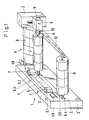
- Figure 1 shows schematically a perspective view of a first embodiment of the device according to the invention.
- the device has a guide frame 1 in the inlet area A of the material web B winding up the windings on one side of the material web and a column 2 on the other side.
- An arrow shows the direction of transport of the material web.
- the skimming area of the windings D is designated C.
- the guide frame consists of a fixed outer frame 3 and an inner frame 4 which is displaceable in the plane of the guide frame in the outer frame, both of which delimit a closed guideway 5 for the sliding bearings 6.1, 6.2, 6.3 and 6.4.
- the sliding bearings have winding shafts denoted by 7, which, with their one end section adjacent to the guide frame, are freely rotatable in their respective sliding bearings.
- the column 2 has a height-adjustable sliding bearing 8 with an electric motor 9, the drive shaft 10 of which can be coupled via a coupling 11 to the free end sections of the winding shafts 7 pointing towards the column.
- the column also has a guide rail 12 which can be pivoted about a vertical axis and extends into the plane of the end face 3 ⁇ of the outer frame 3.
- the winding shafts are designed according to the principle of the tensioning shafts or mandrels, so that sleeves pushed onto them for winding the windings can be clamped out of the circulating material web.
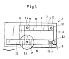
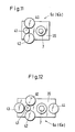
- Figures 2 and 3 each show a side view of the guide frame 1 in Figure 1, namely in the two contact positions of the inner frame on the outer frame.
- the guideway has the two mutually spaced, parallel, horizontal guideway sections 13 and 14 and the two mutually spaced, parallel, vertical guideway sections 15 (FIG. 2) and 16 (FIG. 3) and is in the intermediate positions between the two contact positions of the inner frame on the outer frame self-contained.
- the vertical guideway section 16 is closed in the removal area C, so that the guideway for moving or transporting the sliding bearing consists of the guideway sections 13, 14 and 15, while in Figure 3 the guideway section 15 is closed in the inlet area and the guideway from the is formed from the guide sections 13, 14 and 16.
- the sliding bearing 6.3 has a completely wound winding, while the incoming material web has already formed the first layers of the new winding on the sleeve of the sliding bearing 6.2.
- the sliding bearing 6.3 was in the position of the sliding bearing 6.2 of FIG. 2 during the winding of the winding on it, the free end section of its winding shaft being coupled to the electric motor r of the sliding bearing 8 and its angular velocity was controlled with constant tension of the incoming material web.
- the sliding bearing 6.3 with the completely wound winding is transported or pushed along the guideway section 14 in the direction of the arrow into the removal area.
- the sliding bearing 8 After uncoupling the winding shaft of the sliding bearing 6.3, the sliding bearing 8 is moved into its upper position in the column and coupled to the free end section of the winding shaft of the sliding bearing 6.2, which is in the position of the sliding bearing 6.1 in FIG. 3.
- the inner frame is brought into its contact position shown in FIG. 2 in the removal area C on the outer frame and the sliding bearing 6.3 with the finished winding is transported further in the direction of the arrow along its guideway section.
- the two sliding bearings 6.2 and 8 are brought into the lower position, the sliding bearing 6.2 taking the position shown in FIG. 2.
- the material web is fastened to the winding shaft of the sliding bearing, the winding shaft is set in rotation and the transport speed of the material web previously at rest is regulated in such a way that the tension of the incoming material web is essentially constant.
- the lower horizontal guideway section is extended by the removal track section 20.
- the sliding bearing 6.3 is transported up to the stop 21 of the guideway section 20.
- a lifting table 23 which picks up the winding moves up in the removal area.
- the finished winding is pulled off by moving the lifting table in the axial direction of the winding shaft.
- the sliding bearing 6.3 is brought into the position of the sliding bearing 6.4 according to FIG. 2 and the inner frame into the contact position on the outer frame according to FIG. 3.
- the sliding bearing is transported or pushed in the guideway section 16 according to FIG. 3 into the upper horizontal guideway section 13 (cf. position of the sliding bearing 6.1 (6.4) in FIG. 2 (3)).
- the sliding bearing 6.1 has left its position according to FIG. 2 and is brought into its position according to FIG. 3, in which, after the winding has been wound on the sliding bearing 6.2, it is coupled to the output shaft 10 of the electric motor 9 and into the working position of the sliding bearing 6.2 is brought after this has left the working position with the finished winding.
- the device described with reference to FIGS. 1 to 3 assumes that the material web is stopped each time the winding shafts are changed.
- the guideway can additionally have sliding bearings (not shown) with winding shafts, the arrangement and transportation of the sliding bearings being such that the additional number of sliding bearings is always in the guideway section 13.
- the guideway section then also has the function of a magazine.
- FIG. 4 shows an exemplary embodiment of a device with two guide frames, which are designated by 25 and 26.
- the guide frame 25 is identical to the guide frame 3 in Figure 1 and has sliding bearings 6.1, 6.2, 6.3 and 6.4 with winding shafts 7.
- the guide frame 26 replaces the column 2 in FIG. 1.
- the guide frame 26 has an outer frame 27 and an inner frame 28 which has the dimensions of the inner frame 4 and is brought synchronously with it from the contact position in the inlet area of the material web into the contact position in the removal area of the finished windings.
- sliding bearings are identical to the sliding bearing 8 from FIG. 1 and each have an electric motor 29, the output shaft 30 of which can be coupled to the end sections of the winding shafts 7 via the coupling 31 with the free ones to the guide frame 26.
- the guide frame 26 also has a guide rail 32 which extends into the plane of the end face 3 ⁇ of the outer frame 3.
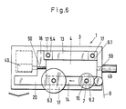
- Figures 5 and 6 each show a side view of the guide frame 1 of Figure 4, which are identical except for the position of individual sliding bearings with Figures 2 and 3.
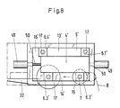
- FIGS. 7 and 8 show the projection of the guide frame 26 and its sliding supports 6.1 ⁇ , 6.2 ⁇ , 6.3 ⁇ and 6.4 ⁇ in the plane E o according to FIG. 4 in the direction of the arrow.
- the sliding bearings 6.1 and 6.1 ⁇ , 6.2 and 6.2 ⁇ , 6.3 and 6.3 ⁇ and 6.4 and 6.4 ⁇ move according to FIGS. 5 to 8, as if they were all coupled to one another via the corresponding couplings 31. In fact, this is only the case for the associated sliding bearings that are actually coupled to one another, specifically from the run-in area of the web to the removal area of the winding.
- the vertical guideway section 16 ⁇ in the removal area C is closed, so that the guideway for moving or transporting the sliding bearing consists of the guideway sections 13 ⁇ , 14 ⁇ and 15 ⁇ , while in Figure 8 the guideway section 15 ⁇ is closed in the inlet area and the guideway consists of the guide sections 13 ⁇ , 14 ⁇ and 16 ⁇ is formed.
- the sliding bearings 6.3 and 6.3 ⁇ have a fully wound winding, while the incoming Material web on the sleeve of the sliding bearings 6.2 and 6.2 ⁇ already forms the first layers of the new winding.
- the sliding bearings 6.3 and 6.3 ⁇ were at the beginning of the winding of the roll located on them in the position of the sliding bearings 6.2 and 6.2 ⁇ of Figures 5 and 7, the free end portion of its winding shaft being coupled to the electric motor of the sliding bearings 6.3 ⁇ and its angular velocity was regulated with constant tension of the incoming material web.
- the sliding bearings move from the position of the sliding bearings 6.2 and 6.2 ⁇ into the position shown in Figures 5 and 7, i.e. from the guideway sections 15 and 15 ⁇ into the guideway sections 14 and 14 ⁇ .
- the sliding layers 6.3 and 6.3 ⁇ with the finished winding are transported or pushed along the guideway section 14 or 14 ⁇ in the direction of the arrow into the removal area until the sliding bearing 6.3 ⁇ stops on the outer frame 27.
- the finished winding is then transported into the removal area until the sliding bearing 6.3 stops on the outer frame 3 and the winding is removed as described above.
- the sliding bearing then moves with its winding shaft into the position corresponding to the sliding bearing 6.4 (cf. FIG. 5).
- the two sliding bearings 6.3 and 6.3 ⁇ are transported from their position corresponding to the sliding bearings 6.4 and 6.4 ⁇ in FIGS. 5 and 7 along the vertical guideway sections 16 and 16 ⁇ into the guideway sections 13 and 13 ⁇ (cf. the position of the sliding bearings 6.4 and 6.4 ⁇ in FIGS. 6 and 8), where, after a sleeve has been clamped onto the tensioning shaft, the free end section of the tensioning shaft is coupled to the output shaft of the motor in the sliding bearing 6.3 ⁇ .
- the sliding bearings 6.3 and 6.3 ⁇ are brought into the position of the sliding bearings 6.4 and 6.4 ⁇ according to FIGS. 6 and 8. While on the winding shaft of the sliding bearing 6.2. and 6.2 ⁇ the new winding is wound further, the sliding bearings 6.2 and 6.2 move. in the direction of the arrow in the guideway sections 14 and 14 ⁇ .
- the inner frames 4 and 28 are brought into contact with their outer frames in the removal area for the winding shafts and the guideway sections 15 and 15 ⁇ (see FIGS. 5 and 7) are released.
- the movement of the sliding bearings 6.1 and 6.1 ⁇ in the vertical guideway sections 15 and 15 ⁇ is controlled such that after the manufacture of the winding on the winding shaft of the sliding bearings 6.2 and 6.2 ⁇ the sleeve located on the winding shaft of the sliding bearings 6.1 and 6.1 ⁇ has a peripheral speed , which has the web speed of the incoming material web, this is cut through and the new beginning of the material web formed without interruptions in operation, ie in the flying change of the winding shaft of the sliding bearings 6.1 and 6.1 ⁇ for winding a new winding.
- the finished winding is removed and the new one is wound.
- the device according to FIGS. 4 to 8 can work both in continuous operation, as described above, and in discontinuous operation in accordance with the device described in FIGS. 1 to 4.
- the winding shaft is freely rotatable in the sliding bearing 6.a. On it a sleeve 7 ⁇ is arranged, on which a winding D is wound.
- the free end portion of the winding shaft is designed as a pin 33 with an end circular disk 34 with a larger diameter than the winding shaft.
- An axially disengageable clutch 36 is arranged in the housing 35 of the sliding bearing, the clutch jaws 37 and 38 of which engage behind the circular disk 34 in the coupled state
- the free end section or pin 33 is fed from the guide rail 12 (FIG. 1) or the guide profile 32 (FIG. 4).
- FIG. 10 shows an exemplary embodiment for a sliding bearing 6a or 6a ⁇ . It has a housing 39, in which the winding shaft 7 is freely rotatable, and further on the top, in the direction of the outer frame, a drive winding 40 and on the underside, in the direction of the inner frame, a corresponding drive winding, not shown. Both drive windings are designed as pinions and are in engagement with the guide track sections 13 or 14 or 13 ⁇ or 14 ⁇ designed as toothed racks.
- 16 ⁇ hydraulic or pneumatic working cylinders, which are not shown, are arranged in the inlet area or removal area below the outer frame and which pass through the outer frames with openings with their piston rods and raise or lower the sliding bearings.
- Figure 11 shows a section through the sliding bearing 6a or 6.a ⁇ . It has an electric motor, the output pinion designated 41 engages with the upper transport roller 40 and the lower transport roller 42.
- Figure 12 shows a further embodiment of a sliding bearing 6.a or 6.a ⁇ .
- rollers 43 and 44 which are designed as pinions and are in engagement with the vertical guide track sections 15 and 16 or 15 ⁇ and 16 ⁇ , which are also designed according to the rack and pinion principle.
- FIG. 13 shows in the representation of FIGS. 1 and 4 the guide frame 1 in a detail and in an enlarged representation in the inlet area of the material web B.
- the design of the guide path sections according to the toothed rack principle is shown for the guide path section 14 by the teeth of the bottom 45 of the guide groove 47. Both the outer frame and the inner frame have such guide grooves with teeth.
- the sliding bearings 6.1, 6.2 and the sliding bearings 6.3 and 6.4 additionally have electric drives 48, with the output shafts of which the winding shafts 7 are connected .
- the sliding bearings 6.a ⁇ not shown, have only couplings for the free end sections of the winding shafts, and optionally additional drives with output pinion 41 (FIG. 11) for drive rollers.
- the outer frames have flanged hydraulic or pneumatic working cylinders 49 on, which move 50 openings with their piston rods through the outer frame during the displacement and alternately stand against the inner frame ( Figures 1 to 8). With their control system, not shown, these working cylinders form a changing device.
- Roller wedges can also take the place of the working cylinders, which wedge into corresponding blind holes in the inner frame during the respective displacement of the inner frame.
- FIG. 14 shows a further exemplary embodiment for displacing the inner frame in the illustration in FIG. 13.
- the displaceably guided inner frame has in the region of the guideway sections 13 and 14 in each case a groove 53 or 54, the bottom of which has a toothing which is denoted by 55.
- the sliding bearing we n, as shown for the sliding bearing 6.1, as a locking element on a vertically adjustable bolt 57 which plunges into a blind hole 58 (see FIG. 15) during the displacement of the inner frame and locks the relevant sliding bearing on the outer frame.
- the sliding bearings also have a drive, not shown, with an output pinion 59, which is in engagement with the teeth 55 of the groove in question.
- the output pinions are acted upon, which engage with the toothing of the bottom of the grooves 53 and 54 according to the toothed rack principle and move the inner frame into the other end position.
- the drives of the output pinion 59 are then switched off and the locking bolts are brought into the rest position.
- the sliding bearings are then transported further as described above.
- FIG. 16 schematically shows a perspective view of a first embodiment of the device according to the invention. Parts corresponding to FIG. 4 or FIG. 1 are identified by the same reference numerals.
- the device has a first guide frame 61 in the inlet area A of the material web B to be wound into windings on one side of the material web and a second guide frame 26 on the other side.
- An arrow shows the direction of transport of the material web.
- the removal range of the windings D is labeled C.
- the guide frame 61 consists of a fixed outer frame 62 and an inner frame 63 which is displaceable in the plane of the guide frame in the outer frame, both of which delimit a self-contained guide path for the sliding bearings 6.1, 6.2, 6.3 and 6.4.
- the self-contained guideway means that the sliding bearings move along a closed path consisting of straight sections.
- the section of the outer frame 6.2 with the plane E o corresponds to a U-profile and runs above the self-contained guideway into the two free legs 64 and 65.
- the guide frame 26 is formed like the frame 26 in Fig. 4, i.e. identical to him.
- the guide frame 26 can also be designed, i.e. with an open outer frame, so that, for example, a winding shaft with its sliding bearings as a complete structural unit can be exchanged as quickly as possible with an indoor crane.
Landscapes
- Winding Of Webs (AREA)
- Replacement Of Web Rolls (AREA)
- Storage Of Web-Like Or Filamentary Materials (AREA)
- Registering, Tensioning, Guiding Webs, And Rollers Therefor (AREA)
Priority Applications (1)
| Application Number | Priority Date | Filing Date | Title |
|---|---|---|---|
| AT87114116T ATE54905T1 (de) | 1986-10-04 | 1987-09-27 | Vorrichtung mit mindestens einem fuehrungsrahmen fuer die schiebelager der wickelwellen fuer aufzuwickelnde materialbahnen. |
Applications Claiming Priority (2)
| Application Number | Priority Date | Filing Date | Title |
|---|---|---|---|
| DE3633897 | 1986-10-04 | ||
| DE19863633897 DE3633897A1 (de) | 1986-10-04 | 1986-10-04 | Wickelvorrichtung mit einem oder zwei beidseitig angeordneten fuehrungsrahmen fuer die schiebelager der wickelwellen fuer aufzuwickelnde materialbahnen |
Publications (2)
| Publication Number | Publication Date |
|---|---|
| EP0263389A1 true EP0263389A1 (fr) | 1988-04-13 |
| EP0263389B1 EP0263389B1 (fr) | 1990-07-25 |
Family
ID=6311090
Family Applications (1)
| Application Number | Title | Priority Date | Filing Date |
|---|---|---|---|
| EP87114116A Expired - Lifetime EP0263389B1 (fr) | 1986-10-04 | 1987-09-27 | Dispositif avec au moins un cadre de guidage pour les paliers mobiles des broches des bobines pour bandes à enrouler |
Country Status (7)
| Country | Link |
|---|---|
| US (1) | US4787568A (fr) |
| EP (1) | EP0263389B1 (fr) |
| JP (1) | JPS6397553A (fr) |
| AT (1) | ATE54905T1 (fr) |
| DE (1) | DE3633897A1 (fr) |
| ES (1) | ES2017689B3 (fr) |
| GR (1) | GR3000866T3 (fr) |
Cited By (1)
| Publication number | Priority date | Publication date | Assignee | Title |
|---|---|---|---|---|
| EP0567091A1 (fr) * | 1992-04-23 | 1993-10-27 | TEIJIN SEIKI CO. Ltd. | Dispositif pour le bobinage de fil à changement automatique des bobines |
Families Citing this family (3)
| Publication number | Priority date | Publication date | Assignee | Title |
|---|---|---|---|---|
| DE3731748A1 (de) * | 1986-10-04 | 1989-04-06 | Schmidt Erwepa Maschf | Vorrichtung mit zwei fuehrungsrahmen fuer die schiebelager der wickelwellen fuer aufzuwickelnde materialbahnen |
| DE3637634A1 (de) * | 1986-11-05 | 1988-05-19 | Schmidt Erwepa Maschf | Verfahren und vorrichtung zum wickeln von materialbahnen zu wicklungen |
| US6502783B1 (en) * | 2000-08-15 | 2003-01-07 | Micron Technology, Inc. | Carrier tape recycling apparatus and method of recycling carrier tape |
Citations (1)
| Publication number | Priority date | Publication date | Assignee | Title |
|---|---|---|---|---|
| EP0145029B1 (fr) * | 1983-12-03 | 1988-04-13 | Werner Mülfarth | Dispositif d'enroulement ou de déroulement à plusieurs arbres en cascade |
Family Cites Families (9)
| Publication number | Priority date | Publication date | Assignee | Title |
|---|---|---|---|---|
| US2840320A (en) * | 1956-05-10 | 1958-06-24 | Csutor Frank | Tape winding bar loader and unloader |
| US3406924A (en) * | 1965-07-09 | 1968-10-22 | Stamco Inc | Apparatus for winding coils of metal strip material |
| US3977617A (en) * | 1973-07-12 | 1976-08-31 | Salmon Marion B | Film winding and perforating apparatus |
| JPS548714Y2 (fr) * | 1975-04-12 | 1979-04-20 | ||
| US4063692A (en) * | 1976-06-11 | 1977-12-20 | Vista Developments, Inc. | Web winding apparatus |
| US4270707A (en) * | 1979-07-30 | 1981-06-02 | Liquid Paper Corporation | Typewriter ribbon spool core shaft adapter |
| JPS6055416B2 (ja) * | 1979-10-26 | 1985-12-05 | 富士写真フイルム株式会社 | ウエブ巻取装置 |
| US4391415A (en) * | 1981-04-23 | 1983-07-05 | Sutco, Inc. | Facilitating the exchange of a finished package with a new core |
| US4498640A (en) * | 1982-05-05 | 1985-02-12 | Owens-Illinois, Inc. | Apparatus and method for uniformly winding elongate sheet materials |
-
1986
- 1986-10-04 DE DE19863633897 patent/DE3633897A1/de active Granted
-
1987
- 1987-09-27 AT AT87114116T patent/ATE54905T1/de not_active IP Right Cessation
- 1987-09-27 ES ES87114116T patent/ES2017689B3/es not_active Expired - Lifetime
- 1987-09-27 EP EP87114116A patent/EP0263389B1/fr not_active Expired - Lifetime
- 1987-10-05 JP JP62250059A patent/JPS6397553A/ja active Granted
- 1987-10-05 US US07/104,380 patent/US4787568A/en not_active Expired - Fee Related
-
1990
- 1990-09-26 GR GR90400701T patent/GR3000866T3/el unknown
Patent Citations (1)
| Publication number | Priority date | Publication date | Assignee | Title |
|---|---|---|---|---|
| EP0145029B1 (fr) * | 1983-12-03 | 1988-04-13 | Werner Mülfarth | Dispositif d'enroulement ou de déroulement à plusieurs arbres en cascade |
Cited By (2)
| Publication number | Priority date | Publication date | Assignee | Title |
|---|---|---|---|---|
| EP0567091A1 (fr) * | 1992-04-23 | 1993-10-27 | TEIJIN SEIKI CO. Ltd. | Dispositif pour le bobinage de fil à changement automatique des bobines |
| US5431352A (en) * | 1992-04-23 | 1995-07-11 | Teijin Seiki Co., Ltd. | Yarn winding apparatus of an automatic bobbin changing type |
Also Published As
| Publication number | Publication date |
|---|---|
| DE3633897C2 (fr) | 1988-09-08 |
| ES2017689B3 (es) | 1991-03-01 |
| JPH0466776B2 (fr) | 1992-10-26 |
| JPS6397553A (ja) | 1988-04-28 |
| DE3633897A1 (de) | 1988-04-14 |
| GR3000866T3 (en) | 1991-11-15 |
| ATE54905T1 (de) | 1990-08-15 |
| EP0263389B1 (fr) | 1990-07-25 |
| US4787568A (en) | 1988-11-29 |
Similar Documents
| Publication | Publication Date | Title |
|---|---|---|
| DE3908010C2 (de) | Schneideinrichtung für Bahn- bzw. Lagen-Materialien oder dgl. | |
| DE2823326A1 (de) | Endstation einer maschine zur behandlung bandfoermigen materials, beispielsweise einer druckmaschine | |
| DE3540490C1 (de) | Wickelmaschine zum Aufwickeln einer laengsgeteilten Bahn | |
| CH656823A5 (de) | Verfahren und vorrichtung zum positionieren von werkzeugen. | |
| EP0313859A2 (fr) | Dispositif pour enrouler ou dérouler des matériaux en forme de feuille continue ou de bande | |
| DE2902479A1 (de) | Vorrichtung zum austausch sich drehender wickeldorne, auf die eine bahn aufgewickelt wird | |
| EP0665722B1 (fr) | Procede et dispositif pour convoyer des pieces planes | |
| EP0145029A2 (fr) | Dispositif d'enroulement ou de déroulement à plusieurs arbres en cascade | |
| DE4304469A1 (de) | Wickelvorrichtung mit Rollenwechseleinrichtung für aufzuwickelndes bandförmiges Wickelgut | |
| EP0203328A2 (fr) | Dispositif de déplacement des lames inférieures | |
| EP3237315B1 (fr) | Dispositif de prélèvement de rouleaux, dispositif d'enroulement et procédé d'évacuation de plusieurs rouleaux complètement enroulés | |
| EP0263389B1 (fr) | Dispositif avec au moins un cadre de guidage pour les paliers mobiles des broches des bobines pour bandes à enrouler | |
| DE2411300B1 (de) | Einrichtung zum Zusammenlegen einer unteren Decklage, einer Mittellage und einer oberen Decklage zu einem Stapel im Zuge der Herstellung von vergüteten Trägerplatten und dgl | |
| EP1108669A2 (fr) | Dispositif d'enroulage de bobines, en particulier pour une refendeuse | |
| DE3731748A1 (de) | Vorrichtung mit zwei fuehrungsrahmen fuer die schiebelager der wickelwellen fuer aufzuwickelnde materialbahnen | |
| EP2371480B1 (fr) | Centre de traitement de profilés | |
| DE1123898B (de) | Vorrichtung zur Verbindung stumpf aneinanderliegender Bahnenden | |
| EP0887297A2 (fr) | Dispositif d'enroulage pour une bande de matière, en particulier pour un dispositif de coupe à rouleaux | |
| DE3637634C2 (fr) | ||
| DE3912684A1 (de) | Walzenstrasse zum profilwalzen von baendern (laengsnaht-rohrschweissen) | |
| DE2635865C2 (de) | Fliegende Schere | |
| DE69831280T2 (de) | Verfahren und Vorrichtung zum Anbringen einer Materialschicht auf eine zu beschichtende Platte, vorzugsweise auf eine Glasscheibe | |
| DE60118964T2 (de) | Vorrichtung und verfahren zum wickeln von bahnen | |
| DE1915817A1 (de) | Werkstueck-Fertigungsanlage | |
| DE60109323T2 (de) | Vorrichtung und verfahren zum wickeln von bahnen |
Legal Events
| Date | Code | Title | Description |
|---|---|---|---|
| PUAI | Public reference made under article 153(3) epc to a published international application that has entered the european phase |
Free format text: ORIGINAL CODE: 0009012 |
|
| 17P | Request for examination filed |
Effective date: 19870927 |
|
| AK | Designated contracting states |
Kind code of ref document: A1 Designated state(s): AT BE CH ES FR GB GR IT LI NL SE |
|
| 17Q | First examination report despatched |
Effective date: 19890811 |
|
| RAP1 | Party data changed (applicant data changed or rights of an application transferred) |
Owner name: ER-WE-PA MASCHINENFABRIK GMBH |
|
| ITF | It: translation for a ep patent filed | ||
| GRAA | (expected) grant |
Free format text: ORIGINAL CODE: 0009210 |
|
| AK | Designated contracting states |
Kind code of ref document: B1 Designated state(s): AT BE CH ES FR GB GR IT LI NL SE |
|
| REF | Corresponds to: |
Ref document number: 54905 Country of ref document: AT Date of ref document: 19900815 Kind code of ref document: T |
|
| GBT | Gb: translation of ep patent filed (gb section 77(6)(a)/1977) | ||
| ET | Fr: translation filed | ||
| REG | Reference to a national code |
Ref country code: GR Ref legal event code: FG4A Free format text: 3000866 |
|
| PLBE | No opposition filed within time limit |
Free format text: ORIGINAL CODE: 0009261 |
|
| STAA | Information on the status of an ep patent application or granted ep patent |
Free format text: STATUS: NO OPPOSITION FILED WITHIN TIME LIMIT |
|
| 26N | No opposition filed | ||
| ITTA | It: last paid annual fee | ||
| PGFP | Annual fee paid to national office [announced via postgrant information from national office to epo] |
Ref country code: SE Payment date: 19920710 Year of fee payment: 6 |
|
| PGFP | Annual fee paid to national office [announced via postgrant information from national office to epo] |
Ref country code: GR Payment date: 19920715 Year of fee payment: 6 |
|
| PGFP | Annual fee paid to national office [announced via postgrant information from national office to epo] |
Ref country code: FR Payment date: 19920716 Year of fee payment: 6 |
|
| PGFP | Annual fee paid to national office [announced via postgrant information from national office to epo] |
Ref country code: GB Payment date: 19920917 Year of fee payment: 6 |
|
| PGFP | Annual fee paid to national office [announced via postgrant information from national office to epo] |
Ref country code: AT Payment date: 19920924 Year of fee payment: 6 |
|
| PGFP | Annual fee paid to national office [announced via postgrant information from national office to epo] |
Ref country code: NL Payment date: 19920930 Year of fee payment: 6 Ref country code: ES Payment date: 19920930 Year of fee payment: 6 |
|
| PGFP | Annual fee paid to national office [announced via postgrant information from national office to epo] |
Ref country code: BE Payment date: 19921002 Year of fee payment: 6 |
|
| PGFP | Annual fee paid to national office [announced via postgrant information from national office to epo] |
Ref country code: CH Payment date: 19921222 Year of fee payment: 6 |
|
| PG25 | Lapsed in a contracting state [announced via postgrant information from national office to epo] |
Ref country code: AT Effective date: 19930927 Ref country code: GB Effective date: 19930927 |
|
| PG25 | Lapsed in a contracting state [announced via postgrant information from national office to epo] |
Ref country code: SE Effective date: 19930928 Ref country code: ES Free format text: LAPSE BECAUSE OF EXPIRATION OF PROTECTION Effective date: 19930928 |
|
| PG25 | Lapsed in a contracting state [announced via postgrant information from national office to epo] |
Ref country code: CH Effective date: 19930930 Ref country code: BE Effective date: 19930930 Ref country code: LI Effective date: 19930930 |
|
| BERE | Be: lapsed |
Owner name: ER-WE-PA MASCHINENFABRIK G.M.B.H. Effective date: 19930930 |
|
| PG25 | Lapsed in a contracting state [announced via postgrant information from national office to epo] |
Ref country code: GR Free format text: THE PATENT HAS BEEN ANNULLED BY A DECISION OF A NATIONAL AUTHORITY Effective date: 19940331 |
|
| PG25 | Lapsed in a contracting state [announced via postgrant information from national office to epo] |
Ref country code: NL Effective date: 19940401 |
|
| NLV4 | Nl: lapsed or anulled due to non-payment of the annual fee | ||
| GBPC | Gb: european patent ceased through non-payment of renewal fee |
Effective date: 19930927 |
|
| PG25 | Lapsed in a contracting state [announced via postgrant information from national office to epo] |
Ref country code: FR Free format text: LAPSE BECAUSE OF NON-PAYMENT OF DUE FEES Effective date: 19940531 |
|
| REG | Reference to a national code |
Ref country code: CH Ref legal event code: PL |
|
| REG | Reference to a national code |
Ref country code: FR Ref legal event code: ST |
|
| REG | Reference to a national code |
Ref country code: GR Ref legal event code: MM2A Free format text: 3000866 |
|
| EUG | Se: european patent has lapsed |
Ref document number: 87114116.4 Effective date: 19940410 |
|
| REG | Reference to a national code |
Ref country code: ES Ref legal event code: FD2A Effective date: 19990601 |
|
| PG25 | Lapsed in a contracting state [announced via postgrant information from national office to epo] |
Ref country code: IT Free format text: LAPSE BECAUSE OF NON-PAYMENT OF DUE FEES;WARNING: LAPSES OF ITALIAN PATENTS WITH EFFECTIVE DATE BEFORE 2007 MAY HAVE OCCURRED AT ANY TIME BEFORE 2007. THE CORRECT EFFECTIVE DATE MAY BE DIFFERENT FROM THE ONE RECORDED. Effective date: 20050927 |