EP0263397A2 - Kopiergerät mit variabler Vergrösserung - Google Patents
Kopiergerät mit variabler Vergrösserung Download PDFInfo
- Publication number
- EP0263397A2 EP0263397A2 EP87114154A EP87114154A EP0263397A2 EP 0263397 A2 EP0263397 A2 EP 0263397A2 EP 87114154 A EP87114154 A EP 87114154A EP 87114154 A EP87114154 A EP 87114154A EP 0263397 A2 EP0263397 A2 EP 0263397A2
- Authority
- EP
- European Patent Office
- Prior art keywords
- magnification
- limiting
- lens means
- lens
- limiting member
- Prior art date
- Legal status (The legal status is an assumption and is not a legal conclusion. Google has not performed a legal analysis and makes no representation as to the accuracy of the status listed.)
- Granted
Links
- 230000003287 optical effect Effects 0.000 claims abstract description 32
- 230000008859 change Effects 0.000 claims abstract description 19
- 230000001105 regulatory effect Effects 0.000 claims description 4
- 230000000903 blocking effect Effects 0.000 description 18
- 230000009467 reduction Effects 0.000 description 10
- 239000011521 glass Substances 0.000 description 2
- 238000003384 imaging method Methods 0.000 description 2
- 230000007246 mechanism Effects 0.000 description 2
- 238000010276 construction Methods 0.000 description 1
- 230000002542 deteriorative effect Effects 0.000 description 1
- 238000006073 displacement reaction Methods 0.000 description 1
- 238000005286 illumination Methods 0.000 description 1
- 230000004048 modification Effects 0.000 description 1
- 238000012986 modification Methods 0.000 description 1
- 210000001747 pupil Anatomy 0.000 description 1
- 230000003014 reinforcing effect Effects 0.000 description 1
Images



Classifications
-
- G—PHYSICS
- G03—PHOTOGRAPHY; CINEMATOGRAPHY; ANALOGOUS TECHNIQUES USING WAVES OTHER THAN OPTICAL WAVES; ELECTROGRAPHY; HOLOGRAPHY
- G03G—ELECTROGRAPHY; ELECTROPHOTOGRAPHY; MAGNETOGRAPHY
- G03G15/00—Apparatus for electrographic processes using a charge pattern
- G03G15/04—Apparatus for electrographic processes using a charge pattern for exposing, i.e. imagewise exposure by optically projecting the original image on a photoconductive recording material
- G03G15/041—Apparatus for electrographic processes using a charge pattern for exposing, i.e. imagewise exposure by optically projecting the original image on a photoconductive recording material with variable magnification
Definitions
- the present invention relates to a variable magnification copying apparatus by which an original can be copied in various magnifications, more particularly to a variable magnification copying apparatus wherein exposure uniformity is maintained in varied magnification copying operations.
- a slit exposure that is, exposure of a photosensitive member to a light image through a slit
- a variable magnification copying by moving a position of a projection lens for imaging the image light is changed to change the magnification, is also widely used.
- the correction plate there are may proposals including a plurality of slits selectively usable in accordance with a selected magnifications or a plate having a slit which is disposed adjacent to a photosensitive drum and which is moved in a direction perpendicular to a length of the slit (a scanning direction) together with movement of the projection lens upon magnification change.
- the correction of the Cos4 law distribution is imparted to the exposure light source, more particularly, the luminous intensity distribution provided by the light source is deliverately made non-uniform along the length of the slit to compensate the non-uniform Cos4 law distribution.
- the luminous intensity distribution provided by the light source is deliverately made non-uniform along the length of the slit to compensate the non-uniform Cos4 law distribution.
- variable magnification copying apparatus wherein non-uniformity of the exposure amount during varied magnification operation can be corrected without deteriorating the light amount using efficiency.
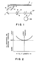
- the copying apparatus includes a transparent platen glass for supporting an original 2 to be copied.
- the original 2 placed on the platen glass 1 is illuminated by a light source 3.
- the light reflected by the original 2 travels to a regulating slit 4 having a constant slit width irrespective of the magnification selected and is reflected by the mirrors 5, 6 and 7.
- the light bearing the image of the original is imaged on a photosensitive drum 38 (image bearing member) after being further reflected by a mirror 37 in the form of a slit having a width which is different depending on the magnification selected.
- the optical system includes a stop plate (pupil) having a round hole for regulating the amount of light.
- the stop plate 9 is disposed in a lens system 8.
- the optical system further includes a light blocking plate 10 disposed adjacent to the lens 8.
- the illumination light source 3 has such a luminous intensity distribution that at a predetermined magnification (unit magnification, for example), the Cos4 law distribution is corrected to provide a uniform illuminance distribution on the photosensitive drum 38, more particularly such that the luminous intensity is higher in the marginal areas than in the central area.
- the lens 8 is displaced to a different position indicated by a lens 8 ⁇ by broken lines along the optical axis, as shown in Figure 1. Simultaneously, the focal length of the lens 8 is changed to maintain the conjugate relationship between the original and the photosensitive member.
- the lens 8 is further moved along the optical axis to a position not shown.
- the magnification When the magnification is simply changed to a non-unit magnification without changing the luminous intensity distribution which has been set so as to provide the uniform exposure at the unit magnification by correcting the Cos4 law distribution as shown in Figure 2, the luminous intensity distribution becomes non-uniform along the length of the slit on the photosensitive drum 12. More particularly, when the luminous intensity distribution is determined to meet the predetermined reference magnification (unit magnification) in the illuminating light source 3, the luminous is high in the marginal areas upon reduction, while it is low in the marginal areas upon enlargement.
- the stop plate 9 in the lens system 8 is displaced in accordance with magnification change, particularly in the direction substantially perpendicular to the optical axis so as to change the relative positional relation with the light blocking member 10, thereby correcting the non-uniform exposure amount upon varied magnification.
- reference L depicts bundles of light rays (wavefront) after passing through the stop plate.
- Figure 3 shows the state at a reference magnification, for example the unit magnification.
- the bundles of projection rays are not blocked by the blocking member 10 upon the unit magnification, and the entire rays reach the photosensitive drum 12 to image there.
- the light source 3 Upon the unit magnification, the light source 3 provides the luminous intensity distribution to correct the non-uniform Cos4 law distribution of the lens 8, and therefore the illuminance distribution on the photosensitive drum 12 is uniform in the direction of the length of the slit.
- Figure 4 shows the bundles of projecting light upon reduction.
- the stop plate 7 moves upwardly in Figure 1 so that the bundles shift upwardly, whereby the bundles adjacent the longitudinal ends of the slit are limited by the light blocking member 10.
- the stop plate 9 is displaced in synchronism with movement of the lens 8 upon magnification change to displace the positions of the bundles of light rays, so that the relative positional relation between the light blocking member 10 disposed adjacent the lens 8 and the bundles of rays is changed to limit the bundles of light.
- the exposure amount non-uniformness can be corrected.
- the light blocking member 10 is displaced to limit the bundles of light rays. However, it is more difficult to limit the converged light rays with the same degree of accuracy. Since the cross-sectional area of the bundles of light is small, even a slight displacement of the light blocking member 10 influences to a greater extent to the correction of the bundles to be passed, and therefore, this is not preferable. In view of this, it is preferable that the stop plate 9 in the lens system 8 is displaced. Particularly, in the case that the lens system has a symmetrical arrangement, it is preferably displaced at a position at the center in the optical axis direction.
- the shape of the light blocking member 10 is reversed, that is, the light blocking member 10 has a height distribution wherein the height in the middle portion is lower than that of the marginal areas to block more light at the central portion, so that the problem of higher illuminance adjacent the center than the marginal area can be removed to make the exposure amount uniform.
- the uniform illuminance can be maintained at a unit magnification plus a reducing magnification or a unit magnification plus an enlarged magnification.
- the light blocking member 10 in this embodiment comprises a light blocking portion 10a in which the marginal portions are closer to the optical axis than the central portion and a light blocking portion 10b in which the central portion thereof is closer to the optical axis than the marginal portions 10b.
- the stop plate 9 in the lens system 8 moved is upwardly to shift the bundles of light upwardly to limit the light in the marginal portions, whereas upon enlargement, it is shifted downwardly to displace the bundles down to limit the light in the marginal portion, so that the non-uniformity of the exposure a mount can be corrected both upon enlargement and reduction.
- the reference magnification is an enlarging magnification. If the reference magnification is set to be the maximum enlargement magnification, the central rays are not limited at any magnifications.
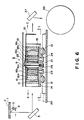
- Figure 6 shows a variable magnification copying apparatus according to this embodiment.
- the optical lens system 6 is displaceable along an optical axis thereof in accordance with magnification change, and it includes a zoom lens system having a continuous variable focal length in accordance with the magnification selected.
- the apparatus according to this embodiment is substantially the same as of Figure 1 except for the lens system described above and the image exposure system.
- the image exposure optical system of Figure 1 the original is fixed, whereas the image exposure optical system is movable to scan the original through the slit, but in this embodiment, the image exposure optical system is stationary, whereas the original is moved to scan the original through the slit.
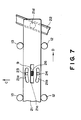
- Figures 6 and 7 illustrate particularly the optical lens system 6.
- a lens base 20 is fixed on a main frame of the copying apparatus.
- a rail 11 is mounted extending in the direction of the optical axis.
- the optical lens system 6 is supported on and guided by the rail 11 through collars 12 and 13. The movement is effected by a motor not shown.
- the optical lens system 6 includes a lens 15 supported in a lens barrel 14, lenses 16a, 16b and 16c supported in another lens barrel 16, a stop plate 9 provided with a substantially rectangular stop aperture 9a ( Figure 8) adjacent a center, lenses 18a, 18b and 18c supported in a further lens barrel 18, a lens 19 and a reinforcing plate 10 which also functions as a light blocking member; these elements are disposed in the order named from the light source side.
- a cam plate 21 is contacted, and the cam plate 21 has curved cam grooves 21a and 21b and an inclined cam groove 21c.
- a projection 21d Adjacent an end of the cam plate 21 a projection 21d is formed extending downward, which is slidably engaged with a rail 22 extending inclinedly with respect to the optical axis at a predetermined angle.
- the cam grooves 21a and 21b are slidably engaged with connecting members 23 and 24, respectively.
- the connecting members 23 and 24 have upper ends fixed to the lens barrels 16 and 18, respectively.
- Figure 8 is a front view of the stop plate 9.
- the top surface of the stop plate 9 is provided with recesses 9b to which leaf springs 25 are engaged at their ends, the leaf springs 25 having the other ends fixed to the upper portion of the lens barrel 18, whereby the stop plate 17 is normally urged downwardly.
- the bottom of the stop plate 9 is engaged with a sliding member 26 which is a cam follower. The sliding member 26 is in contact with the inclined cam groove 21c in the cam plate 21, so that the stop plate 9 is displaceable in a direction perpendicular to the optical axis.
- Figure 9 is a front view of the correcting plate 10 which, as will be understood from the figure, has a curved through aperture 10c.
- the curved aperture is larger in the marginal portions than in the central portion.
- the lens barrel 14 is moved along the rail 11 in the direction indicated by an arrow C.
- the cam plate 21 moves in the direction indicated by an arrow D so that the moving force of the lens barrel 14 along the optical axis is converted to a moving force in a direction different from the direction of the optical axis, more particularly, to the direction substantially perpendicular to the optical axis.
- the stop plate 9 is moved up by the inclined cam groove 21c, and simultaneously, the lens barrels 16 and 19 are moved toward each other by being guided by the cam grooves 21a and 21b, respectively so as to change the focal length of the lens system to that for the reduction imaging.
- the stop plate 9 is moved up upon the magnification change to a reducing magnification, so that the projecting light position L relative to the correcting plate 20 is moved up from the position for the unit magnification ( Figure 10), and therefore, the amount of light at marginal areas is limited as shown in Figure 11.
- the problem of the higher illuminance in the marginal portions upon a reduced magnification is eliminated, whereby the photosensitive drum 38 is exposed to image light with uniform illuminance distribution.
- the lens barrel 14 moves along the rail 11 in the direction indicated by an arrow E, and the stop plate 9 moves down as contrasted to the case of the magnification change to the reduction.
- the lens barrels 16 and 19 are moved away from each other along the cam grooves 21a and 21b, so that the focal length is changed to that for an enlarging magnification.
- the stop plate 9 is moved downwardly upon enlargement so as to shift the positions of the projecting light bundles L, and therefore the light amount in the middle is limited as shown in Figure 12.
- the problem of lower illuminance in the marginal portions is eliminated, whereby the photosensitive drum 38 is exposed to image light with uniform illuminance distribution along the slot.
- the light source is so determined that the illuminance distribution is uniform on the photosensitive drum 38; upon reduction, the amount of light for the marginal portions are limited since otherwise the illuminance at the marginal portions are high; and upon enlargement, the light amount in the middle portion is limited since otherwise the illuminance in the marginal areas is low. Therefore, the illuminance distribution can be made uniform at all times on the photosensitive drum 38, so that the non-uniformity of the amount of exposure light can be corrected.
- the stop plate 9 is moved by cooperation between a slide member and a cam plate which is moved together with the movement of the optical lens system 6 on the rail, whereby the structure is very simple.
- the position of the stop plate is correctly determined in accordance with the lens system position at all times, and therefore, the non-uniformity of the exposure is accurately corrected.
- the accuracy is high in the case of a zoom lens being used, since the cam and the cam follower are associated with the focal length change of the zoom lens.
- the present invention is not limited to the case of the zoom lens used, but is applicable to the case where the lens system has a fixed focal length.
- the correcting plate 10 is disposed at an image side of the lens 19, whereas the stop plate 9 is disposed between the lens barrel 16 and the lens barrel 18, but this is not limiting, and may be changed by ordinary skilled in the art.
- the configuration of the slit of the stop plate 9 and the slit of the correcting plate 10 may be determined in accordance with the positions where they are mounted and the positional relation therebetween.
- the correcting plate 10 preferably has a light blocking portion which is closer to the optical axis in the middle portion than in the marginal portions and a light blocking portion which is closer to the optical axis in the marginal portions than in the central portion, those light blocking portions being opposed to each other.
Landscapes
- Physics & Mathematics (AREA)
- General Physics & Mathematics (AREA)
- Exposure Or Original Feeding In Electrophotography (AREA)
Applications Claiming Priority (4)
| Application Number | Priority Date | Filing Date | Title |
|---|---|---|---|
| JP232769/86 | 1986-09-30 | ||
| JP23276986A JPH0743496B2 (ja) | 1986-09-30 | 1986-09-30 | 画像露光装置 |
| JP1986174640U JPH0645953Y2 (ja) | 1986-11-13 | 1986-11-13 | 画像露光装置 |
| JP174640/86U | 1986-11-13 |
Publications (3)
| Publication Number | Publication Date |
|---|---|
| EP0263397A2 true EP0263397A2 (de) | 1988-04-13 |
| EP0263397A3 EP0263397A3 (en) | 1988-06-01 |
| EP0263397B1 EP0263397B1 (de) | 1992-03-18 |
Family
ID=26496183
Family Applications (1)
| Application Number | Title | Priority Date | Filing Date |
|---|---|---|---|
| EP87114154A Expired EP0263397B1 (de) | 1986-09-30 | 1987-09-28 | Kopiergerät mit variabler Vergrösserung |
Country Status (3)
| Country | Link |
|---|---|
| US (1) | US4894682A (de) |
| EP (1) | EP0263397B1 (de) |
| DE (1) | DE3777519D1 (de) |
Families Citing this family (8)
| Publication number | Priority date | Publication date | Assignee | Title |
|---|---|---|---|---|
| EP0288005B1 (de) * | 1987-04-22 | 1993-06-30 | Canon Kabushiki Kaisha | Bilderzeugungsgerät mit Mitteln zur Leerbelichtung |
| US5060283A (en) * | 1989-04-20 | 1991-10-22 | Fuji Photo Film Co. , Ltd. | Method and system for reading images with a movable light intercepting plate |
| US5287147A (en) * | 1991-01-25 | 1994-02-15 | Canon Kabushiki Kaisha | Original scanning apparatus with fixed light source |
| US5255116A (en) * | 1991-02-18 | 1993-10-19 | Canon Kabushiki Kaisha | Original scanning apparatus |
| JP2979844B2 (ja) * | 1992-05-01 | 1999-11-15 | キヤノン株式会社 | 調整機構を有した撮像装置 |
| JP3224339B2 (ja) * | 1995-10-11 | 2001-10-29 | キヤノン株式会社 | マルチビーム走査光学装置 |
| US7414761B2 (en) * | 2002-05-30 | 2008-08-19 | Canon Kabushiki Kaisha | Imaging optical system and image reading apparatus |
| US20110128533A1 (en) * | 2009-12-01 | 2011-06-02 | Hui-Hsiung Lee | Surface-check equipment |
Family Cites Families (9)
| Publication number | Priority date | Publication date | Assignee | Title |
|---|---|---|---|---|
| JPS5441333B2 (de) * | 1973-03-23 | 1979-12-07 | ||
| CH621414A5 (de) * | 1977-11-15 | 1981-01-30 | Gretag Ag | |
| JPS578515A (en) * | 1980-06-19 | 1982-01-16 | Canon Inc | Zoom lens |
| JPS5781220A (en) * | 1980-11-10 | 1982-05-21 | Asahi Optical Co Ltd | Diaphragm structure body for zoom lens |
| JPS57154265A (en) * | 1981-03-18 | 1982-09-24 | Canon Inc | Correcting device for unevenness of exposure |
| JPS5891475A (ja) * | 1981-11-27 | 1983-05-31 | Canon Inc | 画像形成装置 |
| DE3303283A1 (de) * | 1982-02-01 | 1983-08-11 | Ricoh Co., Ltd., Tokyo | Bildbelichtungssystem |
| JPS5964810A (ja) * | 1982-10-05 | 1984-04-12 | Canon Inc | 変倍投影装置 |
| JPS6022122A (ja) * | 1983-07-18 | 1985-02-04 | Casio Comput Co Ltd | 複写装置 |
-
1987
- 1987-09-24 US US07/100,453 patent/US4894682A/en not_active Expired - Lifetime
- 1987-09-28 DE DE8787114154T patent/DE3777519D1/de not_active Expired - Lifetime
- 1987-09-28 EP EP87114154A patent/EP0263397B1/de not_active Expired
Also Published As
| Publication number | Publication date |
|---|---|
| US4894682A (en) | 1990-01-16 |
| EP0263397A3 (en) | 1988-06-01 |
| DE3777519D1 (de) | 1992-04-23 |
| EP0263397B1 (de) | 1992-03-18 |
Similar Documents
| Publication | Publication Date | Title |
|---|---|---|
| EP0263397B1 (de) | Kopiergerät mit variabler Vergrösserung | |
| US4459016A (en) | Projection device | |
| US4678321A (en) | Anamorphic focusing system | |
| KR19980702257A (ko) | 기판의 폭에 이르는 화상 영역을 갖는 임의의 광 렌즈 어레이 | |
| US3997260A (en) | Improvements in or relating to scanning lens systems for electrostatic copying machines | |
| US4719492A (en) | Scan type anamorphic magnifying apparatus | |
| CA1111009A (en) | Photocopier scanning illumination system | |
| GB2160668A (en) | Focal position adjusting device for small variable magnification type copying machine with zoom lens | |
| JPH0645953Y2 (ja) | 画像露光装置 | |
| US4436415A (en) | Exposure process for use in a variable magnification copying machine | |
| US4740815A (en) | Apparatus for compensating for irregularities of illumination for a copier | |
| EP0902335B1 (de) | Bildlesegerät | |
| JP2687523B2 (ja) | 露光装置の照度むら補正装置 | |
| US4676632A (en) | Variable magnification copying optical system | |
| JP2638962B2 (ja) | 画像露光装置 | |
| US4890137A (en) | Image projection device for use in slit exposure optical system | |
| EP0068000A4 (de) | Optische einheit mit mehrfacher vergrösserung. | |
| JPS58144853A (ja) | 変倍複写機の照度むら補正装置 | |
| JP3595683B2 (ja) | 画像読取装置 | |
| JP2515625Y2 (ja) | 画像露光装置 | |
| JPH0743496B2 (ja) | 画像露光装置 | |
| JPH05341395A (ja) | 画像露光装置 | |
| JPH02157737A (ja) | 複写機の光量分布補正装置 | |
| JPH0713267A (ja) | 変倍複写機 | |
| JPH0786642B2 (ja) | 画像投影装置 |
Legal Events
| Date | Code | Title | Description |
|---|---|---|---|
| PUAI | Public reference made under article 153(3) epc to a published international application that has entered the european phase |
Free format text: ORIGINAL CODE: 0009012 |
|
| 17P | Request for examination filed |
Effective date: 19870928 |
|
| AK | Designated contracting states |
Kind code of ref document: A2 Designated state(s): DE FR GB IT NL |
|
| PUAL | Search report despatched |
Free format text: ORIGINAL CODE: 0009013 |
|
| AK | Designated contracting states |
Kind code of ref document: A3 Designated state(s): DE FR GB IT NL |
|
| 17Q | First examination report despatched |
Effective date: 19900711 |
|
| GRAA | (expected) grant |
Free format text: ORIGINAL CODE: 0009210 |
|
| AK | Designated contracting states |
Kind code of ref document: B1 Designated state(s): DE FR GB IT NL |
|
| REF | Corresponds to: |
Ref document number: 3777519 Country of ref document: DE Date of ref document: 19920423 |
|
| ITF | It: translation for a ep patent filed | ||
| ET | Fr: translation filed | ||
| PLBE | No opposition filed within time limit |
Free format text: ORIGINAL CODE: 0009261 |
|
| STAA | Information on the status of an ep patent application or granted ep patent |
Free format text: STATUS: NO OPPOSITION FILED WITHIN TIME LIMIT |
|
| 26N | No opposition filed | ||
| REG | Reference to a national code |
Ref country code: GB Ref legal event code: IF02 |
|
| PGFP | Annual fee paid to national office [announced via postgrant information from national office to epo] |
Ref country code: FR Payment date: 20050823 Year of fee payment: 19 |
|
| PGFP | Annual fee paid to national office [announced via postgrant information from national office to epo] |
Ref country code: NL Payment date: 20050915 Year of fee payment: 19 |
|
| PGFP | Annual fee paid to national office [announced via postgrant information from national office to epo] |
Ref country code: DE Payment date: 20050922 Year of fee payment: 19 |
|
| PGFP | Annual fee paid to national office [announced via postgrant information from national office to epo] |
Ref country code: GB Payment date: 20050928 Year of fee payment: 19 |
|
| PGFP | Annual fee paid to national office [announced via postgrant information from national office to epo] |
Ref country code: IT Payment date: 20060930 Year of fee payment: 20 |
|
| PG25 | Lapsed in a contracting state [announced via postgrant information from national office to epo] |
Ref country code: NL Free format text: LAPSE BECAUSE OF NON-PAYMENT OF DUE FEES Effective date: 20070401 |
|
| PG25 | Lapsed in a contracting state [announced via postgrant information from national office to epo] |
Ref country code: DE Free format text: LAPSE BECAUSE OF NON-PAYMENT OF DUE FEES Effective date: 20070403 |
|
| GBPC | Gb: european patent ceased through non-payment of renewal fee |
Effective date: 20060928 |
|
| NLV4 | Nl: lapsed or anulled due to non-payment of the annual fee |
Effective date: 20070401 |
|
| REG | Reference to a national code |
Ref country code: FR Ref legal event code: ST Effective date: 20070531 |
|
| PG25 | Lapsed in a contracting state [announced via postgrant information from national office to epo] |
Ref country code: GB Free format text: LAPSE BECAUSE OF NON-PAYMENT OF DUE FEES Effective date: 20060928 |
|
| PG25 | Lapsed in a contracting state [announced via postgrant information from national office to epo] |
Ref country code: FR Free format text: LAPSE BECAUSE OF NON-PAYMENT OF DUE FEES Effective date: 20061002 |