EP0263454A2 - Elément de chauffage plat - Google Patents
Elément de chauffage plat Download PDFInfo
- Publication number
- EP0263454A2 EP0263454A2 EP87114465A EP87114465A EP0263454A2 EP 0263454 A2 EP0263454 A2 EP 0263454A2 EP 87114465 A EP87114465 A EP 87114465A EP 87114465 A EP87114465 A EP 87114465A EP 0263454 A2 EP0263454 A2 EP 0263454A2
- Authority
- EP
- European Patent Office
- Prior art keywords
- wall
- flat
- shells
- radiator according
- wall shells
- Prior art date
- Legal status (The legal status is an assumption and is not a legal conclusion. Google has not performed a legal analysis and makes no representation as to the accuracy of the status listed.)
- Ceased
Links
Images


Classifications
-
- F—MECHANICAL ENGINEERING; LIGHTING; HEATING; WEAPONS; BLASTING
- F28—HEAT EXCHANGE IN GENERAL
- F28F—DETAILS OF HEAT-EXCHANGE AND HEAT-TRANSFER APPARATUS, OF GENERAL APPLICATION
- F28F3/00—Plate-like or laminated elements; Assemblies of plate-like or laminated elements
- F28F3/02—Elements or assemblies thereof with means for increasing heat-transfer area, e.g. with fins, with recesses, with corrugations
- F28F3/025—Elements or assemblies thereof with means for increasing heat-transfer area, e.g. with fins, with recesses, with corrugations the means being corrugated, plate-like elements
-
- F—MECHANICAL ENGINEERING; LIGHTING; HEATING; WEAPONS; BLASTING
- F28—HEAT EXCHANGE IN GENERAL
- F28D—HEAT-EXCHANGE APPARATUS, NOT PROVIDED FOR IN ANOTHER SUBCLASS, IN WHICH THE HEAT-EXCHANGE MEDIA DO NOT COME INTO DIRECT CONTACT
- F28D1/00—Heat-exchange apparatus having stationary conduit assemblies for one heat-exchange medium only, the media being in contact with different sides of the conduit wall, in which the other heat-exchange medium is a large body of fluid, e.g. domestic or motor car radiators
- F28D1/02—Heat-exchange apparatus having stationary conduit assemblies for one heat-exchange medium only, the media being in contact with different sides of the conduit wall, in which the other heat-exchange medium is a large body of fluid, e.g. domestic or motor car radiators with heat-exchange conduits immersed in the body of fluid
- F28D1/03—Heat-exchange apparatus having stationary conduit assemblies for one heat-exchange medium only, the media being in contact with different sides of the conduit wall, in which the other heat-exchange medium is a large body of fluid, e.g. domestic or motor car radiators with heat-exchange conduits immersed in the body of fluid with plate-like or laminated conduits
- F28D1/0308—Heat-exchange apparatus having stationary conduit assemblies for one heat-exchange medium only, the media being in contact with different sides of the conduit wall, in which the other heat-exchange medium is a large body of fluid, e.g. domestic or motor car radiators with heat-exchange conduits immersed in the body of fluid with plate-like or laminated conduits the conduits being formed by paired plates touching each other
-
- F—MECHANICAL ENGINEERING; LIGHTING; HEATING; WEAPONS; BLASTING
- F28—HEAT EXCHANGE IN GENERAL
- F28D—HEAT-EXCHANGE APPARATUS, NOT PROVIDED FOR IN ANOTHER SUBCLASS, IN WHICH THE HEAT-EXCHANGE MEDIA DO NOT COME INTO DIRECT CONTACT
- F28D21/00—Heat-exchange apparatus not covered by any of the groups F28D1/00 - F28D20/00
- F28D2021/0019—Other heat exchangers for particular applications; Heat exchange systems not otherwise provided for
- F28D2021/0035—Other heat exchangers for particular applications; Heat exchange systems not otherwise provided for for domestic or space heating, e.g. heating radiators
-
- Y—GENERAL TAGGING OF NEW TECHNOLOGICAL DEVELOPMENTS; GENERAL TAGGING OF CROSS-SECTIONAL TECHNOLOGIES SPANNING OVER SEVERAL SECTIONS OF THE IPC; TECHNICAL SUBJECTS COVERED BY FORMER USPC CROSS-REFERENCE ART COLLECTIONS [XRACs] AND DIGESTS
- Y02—TECHNOLOGIES OR APPLICATIONS FOR MITIGATION OR ADAPTATION AGAINST CLIMATE CHANGE
- Y02B—CLIMATE CHANGE MITIGATION TECHNOLOGIES RELATED TO BUILDINGS, e.g. HOUSING, HOUSE APPLIANCES OR RELATED END-USER APPLICATIONS
- Y02B30/00—Energy efficient heating, ventilation or air conditioning [HVAC]
Definitions
- the invention relates to a flat radiator, consisting of at least two wall shells of a plate-like basic configuration arranged parallel to one another, which are connected to one another in a circumferential manner, forming a flow path for the heating medium between their mutually facing inner broad sides, brought into mutual contact in areas between their edges and in the System areas are spot welded together.
- Flat radiators of the specified type are known, in which the two wall shells have an identical design with one another with an upper and a lower horizontal bead and vertical beads extending between them.
- the beads opposite each other in the two wall shells form horizontal and vertical channels which in this way provide the heating medium, in particular hot water, with a defined flow path through the heating element.
- the two wall shells are brought into mutual contact and are joined here by spot welds so that the flat radiator has the required strength at the pressures that occur during heating operation.
- the angege benen type only the inner wall shell is provided with the horizontal and vertical beads to form the flow path for the heating medium, while the outer wall shell is flat and runs in a plane adjacent to the base plane of the inner wall shell, without having any beads or characteristics.
- the edge connection there is again a spot weld between the inner wall shell and the outer wall shell in the contact areas between the edges, which, in the absence of any stiffening effect on the wall shell, is thicker than the beaded inner shell, so that the required compressive strength of the flat radiator in the Operation is maintained.
- a common feature of both known embodiments of flat radiators is a low degree of heat utilization of the heating medium guided through the flow channels, since, based on the total area of the radiator, only small, strip-shaped areas that guide the heating medium are available for heat exchange. For this reason, the heat output of the known radiators is limited.
- the invention has for its object to provide a flat radiator of the type specified, the heat output is improved and in which at the same time the conditions placed on its pressure strengthening are met with simple means.
- This object is achieved according to the invention in a flat radiator of the type specified in that the mutually facing inner broad sides of the two wall shells limit a flat heating medium chamber, the free flow cross section of which is only from the chamber area distributed spot weld connections between the two wall shells is broken in some areas.
- the planar heating medium chamber created in the configuration according to the invention provides the heating medium, such as in particular hot water, with an informal flow path through the heating element, the surface dimensions of which essentially correspond to those of the tabular wall shells.
- the entire outer surface of both the inner wall shell and the outer wall shell is a surface that carries a heating medium and is available for heat exchange, ie the transfer of heat to the room to be heated. In this way, the heat of the heating medium can be better utilized, and a correspondingly improved heating output is achieved.
- the spot-welded connections between the two wall shells distributed over the heating chamber surface ensure the necessary pressure resistance of the radiator in heating mode.
- At least one of the two wall shells preferably the inner wall shell, can be provided with a peripheral edge strip which is offset from its main plane and is firmly connected to the edge of the other wall shell. This peripheral edge connection of the two wall shells is usually done by welding.
- the other of the two wall shells for example the outer wall shell, can be made continuously flat, although it is not necessary to make this wall shell thicker than the wall shell provided with the beaded edge strips to achieve the required compressive strength if, as in a further embodiment of the invention provided that the spot weld connections between the two wall shells are formed in wall areas that point from the main plane at least one of the two wall shells, in this case the outer wall shell, are pronounced and stiffen the wall.
- the other of the two wall shells for example again the outer wall shell, in a manner known per se with an upper and a lower horizontal bead and vertical beads extending between them, all the beads facing the outside of the outer wall shell are directed.
- the spot weld connections between the two wall shells are formed between non-distinctive areas between the vertical beads of the outer wall shell and punctiform wall areas from the main plane of the inner wall shell.
- the two wall shells have a trough-like design with peripheral strips which are offset from their main plane, encircling and firmly connected or welded to one another.
- the spot welded connections between the two wall shells are formed in wall regions which are formed in a punctiform manner from the main planes of both wall shells.
- the convector sheet can be attached to the outside of the inner wall at spacing intervals independent of the design of the inner wall shell, e.g. are welded or glued, with all attachment surfaces of the convector plate on the inner wall shell delimiting the planar heating medium chamber, i.e. a wall surface directly exposed to the heating medium.
- the height of the convector sheet in the embodiment according to the invention can extend essentially over the entire area of the inner wall shell between its lower and its upper edge strip due to the trough-shaped, lower and upper projecting horizontal beads avoiding the formation of the wall shell.
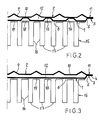
- the flat radiator shown in the drawing consists of two parallel wall shells 1 and 2, which are arranged parallel to one another and have a tabular basic shape, which are formed by suitable steel sheets.
- the inner wall shell 1 has a trough-shaped basic shape, which can be seen in particular in FIG. 3, with a peripheral edge strip 3 offset from its main plane towards the wall shell 2.
- the edge strip 3 comprises an end part 4 running parallel to the main plane of the wall shell 1 and an oblique transition part 5 between the end part 4 and the main part 6 of the wall shell 1 lying in the main plane.
- the edge strip 3 is formed by beading the wall shell 1 on the edge.
- the outer wall shell 2 is provided with an upper bead 7 and a lower bead 8 and vertical beads 9 extending between them.
- the beads 7, 8 and 9 are all pronounced towards the outside of the wall shell 2, ie pointing away from the wall shell 1, from the main plane of the wall shell 2.
- the circumferential edge strip 11 which is also present in the wall shell 2.
- the two wall shells 1 and 2 are tightly welded to one another at their peripheral edge strips 3 and 11 and, with their mutually facing inner broad sides, delimit a flat heating medium chamber 12, the area dimension of which corresponds to the dimensions of the wall shells 1 and 2, minus the welded end parts of the edge strips 3 and 11 , corresponds.
- the heating medium in particular hot water, reaches the heating medium chamber 12 in a manner known per se via a flow connection, flows through it flatly and informally and exits the heating medium chamber 12 from a return connection.
- the inner wall shell 1 is provided, in the manner of a dot pattern, from its main level or its main part 6 toward the wall shell 2, in each case in a manner opposite to a wall strip 10 of the wall shell 2.
- the forms 13 are circular and go over a conical edge 14 into the main part 6 of the wall shell 1.
- the size of the circular area of the shape 13 corresponds to the cross-sectional area of the usual spot weld connections. However, it is also possible to make the shapes square.
- a meandering convector plate 15 is attached to the outside of the inner wall shell 1 and its height extends essentially over the entire area of the inner wall shell 1, ie over the height of the main part 6.
- the convector plate 15 has broad sides 16 which are connected to one another by outer and inner narrow sides 17 and 18.
- the broad sides 16 of the convector plate 15 run at right angles to the main plane or to the main part 6 of the wall shell 1, while the narrow sides 18 running parallel thereto form attachment surfaces for the attachment of the convector plate 15 on the outside of the wall shell 1.
- the attachment can be made by adhesive or welded connections, as is schematically illustrated at 19 in the sectional views.
- the attachment surfaces 18 can be dimensioned and arranged as desired, as is recommended for the permanent attachment of the convector plate 15, the attachment always taking place on a wall surface directly exposed to the heating medium chamber 12, as provided by the main part 6 of the inner wall shell 1 becomes. This creates favorable conditions for the heat transfer from the heating medium to the convector plate 15.
Landscapes
- Engineering & Computer Science (AREA)
- Physics & Mathematics (AREA)
- Thermal Sciences (AREA)
- Mechanical Engineering (AREA)
- General Engineering & Computer Science (AREA)
- Physical Or Chemical Processes And Apparatus (AREA)
- Instantaneous Water Boilers, Portable Hot-Water Supply Apparatuses, And Control Of Portable Hot-Water Supply Apparatuses (AREA)
- Domestic Hot-Water Supply Systems And Details Of Heating Systems (AREA)
- Air-Conditioning For Vehicles (AREA)
- Heat-Exchange Devices With Radiators And Conduit Assemblies (AREA)
Applications Claiming Priority (2)
| Application Number | Priority Date | Filing Date | Title |
|---|---|---|---|
| DE8626670U DE8626670U1 (de) | 1986-10-08 | 1986-10-08 | Flachheizkörper |
| DE8626670U | 1986-10-08 |
Publications (2)
| Publication Number | Publication Date |
|---|---|
| EP0263454A2 true EP0263454A2 (fr) | 1988-04-13 |
| EP0263454A3 EP0263454A3 (fr) | 1988-07-13 |
Family
ID=6798958
Family Applications (1)
| Application Number | Title | Priority Date | Filing Date |
|---|---|---|---|
| EP87114465A Ceased EP0263454A3 (fr) | 1986-10-08 | 1987-10-03 | Elément de chauffage plat |
Country Status (9)
| Country | Link |
|---|---|
| EP (1) | EP0263454A3 (fr) |
| BE (1) | BE905709A (fr) |
| DD (1) | DD262477A5 (fr) |
| DE (1) | DE8626670U1 (fr) |
| DK (1) | DK518787A (fr) |
| FI (1) | FI874362A7 (fr) |
| PT (1) | PT85877A (fr) |
| TR (1) | TR23724A (fr) |
| YU (1) | YU185187A (fr) |
Cited By (2)
| Publication number | Priority date | Publication date | Assignee | Title |
|---|---|---|---|---|
| EP1216786A1 (fr) * | 2000-12-22 | 2002-06-26 | Xenesys Inc. | Procédé de fabrication d'un élément de transfert de chaleur |
| DE202011050322U1 (de) * | 2011-06-01 | 2012-09-03 | Caradon Stelrad B.V. | Rollgeformtes Konvektorblech |
Family Cites Families (6)
| Publication number | Priority date | Publication date | Assignee | Title |
|---|---|---|---|---|
| FR1398806A (fr) * | 1964-03-13 | 1965-05-14 | Finissage De Produits Metallur | Radiateur |
| FR1467538A (fr) * | 1966-02-07 | 1967-01-27 | Wiesbaden Gmbh Maschf | Radiateur à plaques |
| CH503243A (de) * | 1969-06-12 | 1971-02-15 | Strebelwerk Ag | Plattenheizkörper |
| DE3236906A1 (de) * | 1981-10-21 | 1983-06-23 | Schäfer Werke GmbH, 5908 Neunkirchen | Plattenwaermetauscher |
| GB2155167B (en) * | 1982-03-11 | 1986-07-30 | Roger Conway Edmon Pallemaerts | Radiators for space-heating |
| DE8429260U1 (de) * | 1984-10-05 | 1985-01-03 | Prof. Dr. E. Sommer GmbH, 4750 Unna | Flachheizkoerper |
-
1986
- 1986-10-08 DE DE8626670U patent/DE8626670U1/de not_active Expired
- 1986-11-06 BE BE0/217375A patent/BE905709A/fr not_active IP Right Cessation
-
1987
- 1987-10-02 DK DK518787A patent/DK518787A/da not_active Application Discontinuation
- 1987-10-03 EP EP87114465A patent/EP0263454A3/fr not_active Ceased
- 1987-10-05 FI FI874362A patent/FI874362A7/fi not_active IP Right Cessation
- 1987-10-05 DD DD87307658A patent/DD262477A5/de unknown
- 1987-10-07 YU YU01851/87A patent/YU185187A/xx unknown
- 1987-10-07 PT PT85877A patent/PT85877A/pt not_active Application Discontinuation
-
1988
- 1988-10-19 TR TR88/0708A patent/TR23724A/xx unknown
Cited By (2)
| Publication number | Priority date | Publication date | Assignee | Title |
|---|---|---|---|---|
| EP1216786A1 (fr) * | 2000-12-22 | 2002-06-26 | Xenesys Inc. | Procédé de fabrication d'un élément de transfert de chaleur |
| DE202011050322U1 (de) * | 2011-06-01 | 2012-09-03 | Caradon Stelrad B.V. | Rollgeformtes Konvektorblech |
Also Published As
| Publication number | Publication date |
|---|---|
| DK518787A (da) | 1988-04-09 |
| YU185187A (en) | 1990-04-30 |
| BE905709A (fr) | 1987-03-02 |
| TR23724A (tr) | 1990-07-18 |
| DK518787D0 (da) | 1987-10-02 |
| FI874362A7 (fi) | 1988-04-09 |
| EP0263454A3 (fr) | 1988-07-13 |
| DE8626670U1 (de) | 1986-11-27 |
| FI874362A0 (fi) | 1987-10-05 |
| DD262477A5 (de) | 1988-11-30 |
| PT85877A (pt) | 1988-11-30 |
Similar Documents
| Publication | Publication Date | Title |
|---|---|---|
| EP0379873A2 (fr) | Appareil pour chauffeur des gaz | |
| DE69806518T2 (de) | Wärmetauscher und Verfahren zu dessen Herstellung | |
| CH633099A5 (de) | Platten-waermeaustauscher. | |
| DE19858652A1 (de) | Plattenwärmeaustauscher | |
| DE3423736A1 (de) | Kreuzstrom-plattenwaermetauscher | |
| EP0379874A1 (fr) | Dispositif de fixation pour éléments PTC | |
| DE3834822A1 (de) | Waermetauscher | |
| DE2404630C2 (de) | Wärmeaustauscher | |
| EP0092033B1 (fr) | Procédé pour la fabrication d'un échangeur de chaleur à plaques | |
| EP0106262B1 (fr) | Echangeur thermique en particulier radiateur | |
| EP0326813A1 (fr) | Echangeur de chaleur, en particulier un refroidisseur eau-air en aluminium | |
| DE1426622C3 (de) | Durch stark staubhaltige Gase beheizter Wärmetauscher mit Rohrheizflächen | |
| DE2539856C2 (de) | Plattenheizkörper | |
| EP0176997A2 (fr) | Radiateur plat | |
| EP0263454A2 (fr) | Elément de chauffage plat | |
| DE2857177C2 (de) | Heißwasser-Radiator | |
| EP0994320B1 (fr) | Radiateur avec au-moins deux tubes plats superposés | |
| DE2921770C2 (de) | Wärmetauscher | |
| DE102020216483A1 (de) | Wärmeübertrager | |
| DE689056C (de) | Im Parallelstrom durchstroemter Waermeaustauscher unter Verwendung von Platten | |
| DE2720127C3 (de) | Verfahren und Werkzeug zum Herstellen eines Heizkörpers mit mindestens einem profilierten Konvektorblech | |
| DE2821090A1 (de) | Absorberbauteil fuer einen sonnenkollektor | |
| DE10024507B4 (de) | Strahlflächenaufbau | |
| DE3331619C2 (fr) | ||
| DE3329291A1 (de) | Heizkoerper, insbesondere plattenheizkoerper |
Legal Events
| Date | Code | Title | Description |
|---|---|---|---|
| PUAI | Public reference made under article 153(3) epc to a published international application that has entered the european phase |
Free format text: ORIGINAL CODE: 0009012 |
|
| AK | Designated contracting states |
Kind code of ref document: A2 Designated state(s): AT CH DE ES FR GB GR IT LI LU NL SE |
|
| PUAL | Search report despatched |
Free format text: ORIGINAL CODE: 0009013 |
|
| AK | Designated contracting states |
Kind code of ref document: A3 Designated state(s): AT CH DE ES FR GB GR IT LI LU NL SE |
|
| 17P | Request for examination filed |
Effective date: 19890107 |
|
| 17Q | First examination report despatched |
Effective date: 19890626 |
|
| STAA | Information on the status of an ep patent application or granted ep patent |
Free format text: STATUS: THE APPLICATION HAS BEEN REFUSED |
|
| 18R | Application refused |
Effective date: 19910711 |
|
| RIN1 | Information on inventor provided before grant (corrected) |
Inventor name: ALBERS, KLAUS |