EP0263494B1 - Clavier pour instrument de musique électronique - Google Patents
Clavier pour instrument de musique électronique Download PDFInfo
- Publication number
- EP0263494B1 EP0263494B1 EP87114593A EP87114593A EP0263494B1 EP 0263494 B1 EP0263494 B1 EP 0263494B1 EP 87114593 A EP87114593 A EP 87114593A EP 87114593 A EP87114593 A EP 87114593A EP 0263494 B1 EP0263494 B1 EP 0263494B1
- Authority
- EP
- European Patent Office
- Prior art keywords
- key
- keyboard apparatus
- hammer
- weight member
- switch
- Prior art date
- Legal status (The legal status is an assumption and is not a legal conclusion. Google has not performed a legal analysis and makes no representation as to the accuracy of the status listed.)
- Expired - Lifetime
Links
- 230000033001 locomotion Effects 0.000 claims description 35
- 230000000994 depressogenic effect Effects 0.000 claims description 26
- 239000002184 metal Substances 0.000 claims description 26
- 230000001105 regulatory effect Effects 0.000 claims description 23
- 229920005989 resin Polymers 0.000 claims description 22
- 239000011347 resin Substances 0.000 claims description 22
- 239000000463 material Substances 0.000 claims description 20
- 238000005452 bending Methods 0.000 claims description 17
- 230000007246 mechanism Effects 0.000 claims description 16
- 230000005484 gravity Effects 0.000 claims description 14
- 238000003466 welding Methods 0.000 claims description 11
- 230000005489 elastic deformation Effects 0.000 claims description 8
- 238000004519 manufacturing process Methods 0.000 claims description 8
- 230000008878 coupling Effects 0.000 claims description 4
- 238000010168 coupling process Methods 0.000 claims description 4
- 238000005859 coupling reaction Methods 0.000 claims description 4
- 238000003780 insertion Methods 0.000 claims description 4
- 230000037431 insertion Effects 0.000 claims description 4
- 230000004044 response Effects 0.000 claims description 4
- 230000000063 preceeding effect Effects 0.000 claims 7
- 230000001276 controlling effect Effects 0.000 claims 2
- 230000004048 modification Effects 0.000 description 20
- 238000012986 modification Methods 0.000 description 20
- 230000002093 peripheral effect Effects 0.000 description 10
- 238000013016 damping Methods 0.000 description 9
- 229920001971 elastomer Polymers 0.000 description 9
- 230000005540 biological transmission Effects 0.000 description 7
- 230000000694 effects Effects 0.000 description 5
- 229920003002 synthetic resin Polymers 0.000 description 5
- 239000000057 synthetic resin Substances 0.000 description 5
- 230000008859 change Effects 0.000 description 4
- 230000008901 benefit Effects 0.000 description 3
- 239000004033 plastic Substances 0.000 description 3
- 125000006850 spacer group Chemical group 0.000 description 3
- 239000004809 Teflon Substances 0.000 description 2
- 229920006362 Teflon® Polymers 0.000 description 2
- 230000002159 abnormal effect Effects 0.000 description 2
- 229920002379 silicone rubber Polymers 0.000 description 2
- 239000004945 silicone rubber Substances 0.000 description 2
- 230000015572 biosynthetic process Effects 0.000 description 1
- 244000145845 chattering Species 0.000 description 1
- 239000011248 coating agent Substances 0.000 description 1
- 238000000576 coating method Methods 0.000 description 1
- 230000006835 compression Effects 0.000 description 1
- 238000007906 compression Methods 0.000 description 1
- 230000007423 decrease Effects 0.000 description 1
- 238000006073 displacement reaction Methods 0.000 description 1
- 230000006872 improvement Effects 0.000 description 1
- 238000000034 method Methods 0.000 description 1
- 238000000465 moulding Methods 0.000 description 1
- 238000012856 packing Methods 0.000 description 1
- 230000009467 reduction Effects 0.000 description 1
- 230000035939 shock Effects 0.000 description 1
Images







Classifications
-
- G—PHYSICS
- G10—MUSICAL INSTRUMENTS; ACOUSTICS
- G10H—ELECTROPHONIC MUSICAL INSTRUMENTS; INSTRUMENTS IN WHICH THE TONES ARE GENERATED BY ELECTROMECHANICAL MEANS OR ELECTRONIC GENERATORS, OR IN WHICH THE TONES ARE SYNTHESISED FROM A DATA STORE
- G10H1/00—Details of electrophonic musical instruments
- G10H1/32—Constructional details
- G10H1/34—Switch arrangements, e.g. keyboards or mechanical switches specially adapted for electrophonic musical instruments
-
- G—PHYSICS
- G10—MUSICAL INSTRUMENTS; ACOUSTICS
- G10H—ELECTROPHONIC MUSICAL INSTRUMENTS; INSTRUMENTS IN WHICH THE TONES ARE GENERATED BY ELECTROMECHANICAL MEANS OR ELECTRONIC GENERATORS, OR IN WHICH THE TONES ARE SYNTHESISED FROM A DATA STORE
- G10H1/00—Details of electrophonic musical instruments
- G10H1/32—Constructional details
- G10H1/34—Switch arrangements, e.g. keyboards or mechanical switches specially adapted for electrophonic musical instruments
- G10H1/344—Structural association with individual keys
- G10H1/346—Keys with an arrangement for simulating the feeling of a piano key, e.g. using counterweights, springs, cams
-
- Y—GENERAL TAGGING OF NEW TECHNOLOGICAL DEVELOPMENTS; GENERAL TAGGING OF CROSS-SECTIONAL TECHNOLOGIES SPANNING OVER SEVERAL SECTIONS OF THE IPC; TECHNICAL SUBJECTS COVERED BY FORMER USPC CROSS-REFERENCE ART COLLECTIONS [XRACs] AND DIGESTS
- Y10—TECHNICAL SUBJECTS COVERED BY FORMER USPC
- Y10S—TECHNICAL SUBJECTS COVERED BY FORMER USPC CROSS-REFERENCE ART COLLECTIONS [XRACs] AND DIGESTS
- Y10S84/00—Music
- Y10S84/07—Electric key switch structure
Definitions
- the present invention relates to a keyboard apparatus according to the precharacterizing part of claim 1.
- a performer can produce a musical tone by applying a force to a key, wich is a sum of a force required for pivoting the key and a force required for closing the key switch.
- a hammer mass member which produces an inertial effect when a key is depressed
- striking strings must be driven upon depression of a key, thereby increasing a load applied upon depression of a key. Therefore, a performer feels key operation heavier than that of the keyboard apparatus of the above electronic musical instrument.
- the electronic musical instrument can produce a musical tone similar to that produced by an acoustic piano. For this reason, demand has arisen for a keyboard apparatus providing the same key touch feeling as that obtained by a keyboard of the piano.
- a conventional keyboard apparatus of an electronic musical instrument based on the above demand is disclosed in Japanese Patent Laid-Open (Kokai) No. 57-147691.
- each key is pivotally disposed about a fulcrum, and a hammer which is formed independently of the key and is associated therewith is pivotally supported about a fulcrum.
- the hammer is provided to obtain a key touch feeling similar to that obtained by an acoustic piano and has the predetermined mass.
- the center of gravity of the hammer is located at an end corresponding to a rear end of the key, and a point of application of the hammer for pivoting the hammer in correspondence to pivoting motion of the key is arranged at an end opposite to that of the center of gravity and corresponding to a front end of the key.
- the hammer when the key is depressed, the hammer is pivoted through the point of application, and when the key is released, the hammer and the key are pivoted clockwise by the weight of the hammer and returned to initial positions. That is, the depressed key is pivoted against the weight of the hammer, thereby obtaining the key touch feeling.
- the hammer produces the inertial effect upon depression of the key.
- the fulcrum of the hammer is located at the center of a longitudinal direction thereof. Therefore, upon depression of the key, the hammer is pivoted in a direction opposite to a direction along which the center of gravity thereof is lifted, i.e., a pivoting direction of the key, thereby lowering the position (moving distance) of the center of gravity. This is because the hammer abuts against the key which is moved downward when the center of gravity is lifted to a predetermined position.
- US-A 3580979 describes a complicated and relatively large keyboard apparatus comprising a plurality of keys therein. Under each key a lever is swingingly supported at one end by a pivot shaft and provided with a weight at the other end. A drive member fixed to the key transmits the depression of the key to the lever. A bridle rod is fixed to the key to return the lever, when the key is released. The key is pivotally supported at one end by a pin.
- GB-A-112 197 shows a keyboard apparatus wherein special switch contacts are provided for each key such that they are successively closed in an interlocked relation to the operation of the key.
- Fig. 1 shows a principle of the present invention.
- a fulcrum O1 of a hammer (mass member) H is located at the right end of Fig. 1, i.e., below a fulcrum O2 of a key K.
- a center of gravity W of the hammer H is pivoted in a direction D which is the same direction as a pivoting direction (indicated by an arrow C in Fig. 1) of the key K.
- the moving distance of the center of gravity W can be increased by pivoting motion of the hammer H. Therefore, a light piano touch feeling is obtained, the weight of the hammer is reduced, and the height of the keyboard apparatus is reduced. That is, a low-profile compact keyboard apparatus can be obtained.
- Fig. 1 upon depression of a key, the key K and the hammer H are pivoted in the same direction as that (indicated by an arrow) along which the center of gravity W of the hammer H acts. Therefore, in principle, the springs S1 and S2 are required to return the hammer H and the key K, respectively. However, the springs S1 and S2 may be replaced with a single spring as will be described later with reference to the embodiments.
- the pivot fulcrums of the key K and the hammer H are provided at the ends thereof, respectively.
- similar pivoting motion can be obtained even if the fulcrum is not a perfect edge.
- a distance a between the key K and the hammer H will be described below.
- a point where the key K which is pivoting can abut against the hammer H is the hammer fulcrum P1 except for the transmission point T. Therefore, if the hammer fulcrum P1 is provided outside the pivot range of the key K, the key K does not abut against the hammer H except for the transmission point T.
- the distance a between the key K and the hammer H can be arbitrarily set regardless of the pivot range of the hammer H, the distance a can be shorter than that of a conventional apparatus. Therefore, the keyboard apparatus can be low-profile and hence an electronic musical instrument can be made compact.
- the fulcrum O1 of the hammer H is offset from the fulcrum O2 of the key K toward a front side, so that the fulcrum O1 falls outside the pivot range of the key K.
- the key and the hammer can be arranged on a single plane.
- the following embodiments have this arrangement.
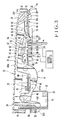
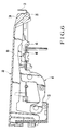
- Figs. 2 to 7 show an embodiment of a keyboard apparatus of an electronic musical instrument according to the present invention.
- reference numeral 31 denotes a frame of the keyboard apparatus; 33, a key (white key) which is supported on the frame 31 and can be pivoted vertically (vertically in Fig. 3) about its proximal end portion 34; and 32, a black key.
- the frame 31 is formed of a metal or the like so as to have predetermined rigidity while the key 33 is formed of, e.g., a synthetic resin.
- the key 33 engages with a pin 35 having a circular section and fixed to the frame 31 at the proximal end portion 34 (right end portion in Fig. 3: see Fig. 4) (an arcuated recess surface 36 is formed in the proximal end portion 34 and pivotally abuts against the pin 35). Therefore, the key 33 can pivot about the pin (key fulcrum) 35 in a vertical plane.
- An upper surface of a distal end portion (left end portion in Fig. 3) of the key 33 is a key depression portion 38.
- the pin 35 is formed by performing so-called outserting to a peripheral edge of a rectangular slit 37 which is formed in the frame 31.
- a notched groove having a predetermined width is formed in the pin 35 to extend along an extension direction of the slit 37 (a longitudinal direction of the key 33).
- the key 33 has substantially a box-like shape, and its lower surface is open.
- a recess portion 39 (hammer drive portion) is formed near a central portion of each side wall of the key 33 at a position.
- each recess portion 39 close to the proximal end portion 34 projects downward to form a projection 40.
- a hammer 41 is disposed below and along the key 33. As shown in Fig. 2, the hammer 41 is bent to be substantially a crank-like shape. As shown in Figs. 2 to 7, the hammer 41 is partially inserted in the box-like key 33.
- the hammer 41 is pivotally supported in the vertical plane described above about a pin 45 which is fixed to the peripheral edge of the slit 37 at a position opposite to the pin 35 (similar to the pin 35, the pin 45 has a circular section and is formed by outserting). That is, the hammer 41 can pivot vertically in the same vertical plane as that of the key 33 about the pin (fulcrum) 45 (i.e., about a proximal end portion (fulcrum) 42 of the hammer 41).
- a semicircular engaging surface 43 is formed on a left side surface (Fig. 3) of the proximal end portion 42 and engages with the pin 45 (i.e., biased by a leaf spring to be described later and urged against the pin 45). Therefore, the pin 45 forms a hammer fulcrum.
- the hammer 41 has a core member (hammer frame) 44 which is formed of a predetermined metal so as to have a predetermined weight.
- a peripheral portion i.e., backward from a portion slightly separated from the fulcrum
- the edge 41A includes a guide portion 41Aa of the hammer 41 at the center thereof and a stopper portion 41Ab at the front side of the key 33.
- the guide portion 41Aa of the hammer which constitutes part of the edge 41A is formed integrally with the stopper portion 41Ab by outserting and prevents an increase in resistance caused by friction between the hammer 41 and the frame 31 when the hammer 41 is pivoted. That is, since the fulcrum 45 of the hammer 41 is formed at a lower rear end portion, the proximal end portion 42 of the hammer 41 is pivoted above the upper surface of the frame 31. Upon depression of a key, the hammer 41 is pivoted in the same direction as that of the key.
- the front end portion of the hammer 41 must be located at a lower surface of the frame 31.
- a slit 60 is formed in the frame 31 so that a middle portion of the hammer 41 passes therethrough. Since the width of the slit 60 is larger than that of the hammer 41, the hammer 41 is not brought into contact with the frame 31 as long as it is pivoted along a constant path. However, when the hammer 41 is pivoted, the path of the hammer 41 is not always constant but changes in a widthwise direction thereof due to a vibration and the like.
- the frame 31 is brought into contact not with the metal body (core member) 44 but with the guide portion 41Aa formed of a soft resin. Therefore, since a resistance value by friction is small, almost no change is produced in a touch feeling for the key and return characteristics thereof. Accordingly, with the above structure, manufacturing cost of the hammer 41 is reduced, and the touch feeling of the key and the return characteristics thereof are easily set.
- the center of gravity of the hammer 41 is located near a distal end portion 46 along the longitudinal direction thereof (i.e., at a left end portion or the front side of the key in Fig. 3).
- the hammer 41 constitutes a mass member which produces an inertial effect upon depression of a key.
- reference numeral 48 denotes a through hole formed in the hammer 41 to adjust the center of gravity.
- a single projection or a forked switch drive portion 50 projects downward near the proximal end portion 42 of the hammer 41. That is, when the hammer 41 is pivoted, the switch drive portion 50 moves downward and abuts against a switch 52.
- the switch 52 is arranged on a printed circuit board 54 which is held by a holder 53 extending downward from a lower surface of the frame 31.
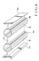
- the switch 52 has a pair of conductive rubber switch portions 56 and 58 having a circular section and connected with each other. That is, as shown in Fig.
- the switch portions 56 and 58 are formed integrally with each other by silicone rubber so as to obtain a pair of urging portions PU each having a circular section, a coupling portion CO for coupling the urging portions PU, and positioning portions PD provided at both sides of the urging portions PU.
- Conductive rubber members are arranged at lower ends of the respective circular sections to constitute one of contacts, i.e., a movable contact.
- the conductive members are arranged to oppose a fixed contact on the printed circuit board 54 through a hole of a spacer. Therefore, upon depression of a key, the switch drive portion 50 abuts against the switch 52 through the slit 60 formed in the frame 31, thereby closing (turning on) the switch 52.
- the switch 52 is of a so-called touch response type and is a so-called 2-make switch in which the two switch portions 56 and 58 are closed at different timings.
- a control circuit CC controls the volume, envelope change, tone color, and the like of a produced musical tone.
- An actuator portion 47 horizontally projects above the switch drive portion 50 of the hammer 41 (Fig. 3).
- the actuator portion 47 pushes down the hammer 41. That is, a lower surface of the recess portion 39 (hammer drive portion) of the key 33 abuts against the actuator portion 47 of the hammer 41.
- the actuator portion 47 consists of a resin base portion 62, a resin abutting portion 63, and a rubber vibration damping portion 64 interposed therebetween.
- the vibration damping portion 64 decreases a shock produced when the key 33 and the hammer 44 strike each other.
- the right side surface Fig.
- the vibration damping portion 64, the base portion 62, and the abutting portion 63 constitute a member removal preventing portion 65 which abuts against the projection 40 and regulates a movement of the key 33 to the left in Fig. 4.
- the member removal preventing portion 65 is provided to the frame 31 through the hammer 41 which is supported by the frame 31, i.e., provided indirectly to the frame 31. Note that the member removal preventing portion 65 may be provided directly to the frame 31.
- the respective portions of the hammer 41 are loosely fitted in slits 66 and 67 formed in the frame 31, as shown in Fig. 3 and the following figures. That is, a plurality of slits 37, 60, 66, 67 are formed in the frame 31.
- An abutting portion 70 projecting to the right in Fig. 3 is formed at a portion (subjected to the outserting) of the hammer 41 which is fitted in the slit 66, i.e., a portion which opposes a right peripheral portion 68 (Fig. 3) of the slit 66 upon depression of a key (Fig. 4).
- Fig. 3 a portion which opposes a right peripheral portion 68
- the abutting portion 70 projects so as to oppose the peripheral portion 68 of the slit 66 at a position separated therefrom by a predetermine distance (small distance) upon depression of a key. That is, the peripheral portion 68 constitutes a regulating portion which abuts against the abutting portion 70 and limits movement (removal) of the hammer 41 to the right.
- stoppers or dampers (felts) 71 and 72 for regulating upper and lower limit positions, respectively, of the hammer 41 are fixed in the frame 31.
- stoppers (felts) 57 and 59 for regulating upper and lower limit positions, respectively, of the key 33 are fixed at predetermined positions of the frame 31 in front of the key 33.
- Reference numerals 74, 75, 76, and 77 denote a guide portion of the white key 33, a guide portion of the black key 32, a lower-limit stopper (felt) for limiting downward movement of a side wall lower end of the black key 32, and a screw hole portion for fixing a musical instrument main body to the frame 31, respectively.
- reference numeral 61 denotes a rectangular leaf spring made of a metal and having a predetermined modulus of elasticity.
- One end portion 80 of the leaf spring 61 abuts against and is locked by a locking groove 63p formed in a position closer to an end (opposite to the engaging surface 43) from the hammer fulcrum (pin) 45 of the distal end portion (one end portion) 42 of the hammer 41.
- the other end portion 81 of the leaf spring 61 having a width smaller than that of the end portion 80 is inserted in a groove 39p which is formed in the pin 35 serving as a fulcrum of pivoting motion of the key 33.
- An upper surface of the end portion 81 pushes up an lower surface of the end portion (proximal end portion) 34 of the key 33.
- the leaf spring 61 is disposed such that the end portion 81 having a smaller width is inserted in the groove 39p in the pin 35, and the upper surface of the end portion 81 is slidably brought into contact with the lower surface of the proximal end portion 34 so that the recess surface 36 of the proximal end portion 34 is urged against the pin 35.
- the end portion 81 of the leaf spring 61 engages with the proximal end portion 34, and the end portion 80 thereof abuts against and is locked by the locking groove 63p.
- the end portion 81 of the leaf spring 61 extends along the longitudinal direction thereof, and a wide portion 81A which is wider than the groove 39p is formed at an extended edge portion of the end portion 81.
- the wide portion 81A serves as a holding portion for holding the leaf spring 61.
- the wide portion (holding portion) 81A abuts against one end wall of the groove 39p in which the end portion 81 is inserted, thereby preventing excessive curving deformation of the leaf spring 61. That is, the wide portion 81A and the groove 39p limit curving deformation of the leaf spring 61. Therefore, the end portion 81 is not detached from the proximal end portion 34 of the key 33, thereby preventing removal of the leaf spring 61. In addition, since removal of the leaf spring 61 is prevented, the proximal end portion 34 of the key 33 is not disengaged from the pin 35, and the proximal end portion 42 of the hammer 41 is not disengaged from the pin 45. Thus, the wide portion 81A and the groove 39p constitute disengagement preventing means.
- a locking portion of the leaf spring may be formed in the proximal end portion of the key, and a groove with which the end portion of the spring is engaged is formed in the proximal end portion of the hammer so that the hammer is urged against the hammer fulcrum.
- the hammer 41 is given a return habit clockwise by a moment of P1 ⁇ r1 along a direction connecting a position of the locking groove 63p with a locking portion 34P of the leaf spring 61 with respect to the key 33, and the key 33 is given the return habit clockwise by a moment of P2 ⁇ r2 therealong.
- a stopper member 83 formed by outserting extends from a side wall portion of the slit 37 of the frame 31.
- the stopper member 83 is disposed above the leaf spring 61 to be separated therefrom by a predetermined interval when a key is not depressed.
- the stopper member 83 limits curving deformation of the leaf spring 61 in the thickness direction thereof. That is, by the stopper member 83, the end portion 81 of the leaf spring 61 is not disengaged from the proximal end portion 34 of the key 33, and hence removal of the leaf spring 61 is prevented.
- the stopper member 83 thus constitutes disengagement preventing means.
- a distance between the stopper member 83 and the leaf spring 61 may be determined on the basis of a distance measured when a key is depressed.
- the stopper member 83 is a gate-like member across the slit 37 in a widthwise direction thereof.
- the stopper member 83 has a pair of leg portions 84 extending from the frame 31, a ceiling portion 87 formed across upper end portions of the leg portions 84, a projecting portion 85 which projects horizontally from the ceiling portion 87, and a projecting portion 86 which obliquely projects downward from the ceiling portion 87.
- the stopper member 83 When the leaf spring 61 is curved and deformed upon depression of a key, the stopper member 83 is sometimes largely deformed. In this case, the leaf spring 61 abuts against a lower surface of the stopper member 83 and hence is prevented from being excessively deformed. At this time, the wide portion 81A (Fig. 9) of the leaf spring 61 abuts against one end of the groove 39p and prevents deformation of the leaf spring 61. As a result, the key 33 is prevented from being detached from the pin 35, i.e., disengagement of the key 33 is prevented.
- the end portion 81 of the leaf spring 61 is prevented from being detached from the proximal end of the key 33, thereby preventing removal of the leaf spring 61 and disengagement of the proximal end portion 42 of the hammer 41 from the pin 45. That is, disengagement of the leaf spring 61 is prevented.
- the key touch feeling can be arbitrarily set, e.g., hard touch, soft touch, and the like can be freely selected.
- the preflexed leaf spring 61 is further flexed by buckling deformation caused by pivoting motion of the hammer 41 along with key depression operation and gives a predetermined restoration force to the hammer 41.
- a resistive force against the pivoting motion produces a key touch feeling, i.e., a dynamic touch feeling.
- an external force required for this deformation is small.
- the performer feels the key touch caused by the pivoting motion of the hammer 41, he or she does not feel resistance caused by the elastic force of the leaf spring 61.
- the end portion 81 of the leaf spring 61 urges the proximal end portion 34 (36) against the pin 35, and the other end portion 80 thereof urges the proximal end portion 42 (43) against the pint 45.
- the end portion 81 of the leaf spring 61 Since the end portion 81 of the leaf spring 61 is urged against the lower surface of the proximal end portion 34 of the key 33, the end portion 81 is curved and deformed by a predetermined amount. When a deformation amount of the end portion 81 increases, the upper surface of the leaf spring 61 abuts against the lower surfaces of the projecting portions 85 and 86 of the stopper member 83, thereby preventing excessive deformation thereof. Therefore, removal of the key 33 from the pin 35, i.e., disengagement thereof is prevented even if the key 33 is pulled toward the distal end in the longitudinal direction thereof. At the same time, the end portion 81 of the leaf spring 61 is prevented from being removed from the proximal end portion 34 of the key 33. Therefore, removal of the leaf spring 61 and disengagement of the proximal end portion 42 of the hammer 41 from the pin (hammer fulcrum) 45 can be prevented. That is, removal of the key 33 and the hammer 41 can
- the key 33 and the hammer 41 have the return habit set by the leaf spring 61. Therefore, when the key 33 is released, the key 33 and the hammer 41 are pivoted in the opposite direction by the biasing force of the leaf spring 61. The key 33 and the hammer 41 abut against the stoppers (felt) 57 and 71 and return to the upper limit positions, respectively.
- the key 33 and the hammer 41 are not detached and are kept in an original assembled state. That is, when the key 33 is moved in the longitudinal direction by a predetermined distance due to the impact force, the projection 40 of the key 33 abuts against the rubber vibration damping portion 64 or the side surface (member removal preventing portion 65) of the base portion 62 thereof, thereby limiting excessive movement in the longitudinal direction of the key 33.
- the abutting portion 70 abuts against the peripheral portion 68 of the slit 66, thereby preventing removal of the hammer 41. Note that in this case, movement (removal) of the key 33 and the hammer 41 in other directions (e.g., a vertical direction in Fig. 2) is prevented by packing materials.
- the key 33 is depressed, and then, as shown in Fig. 6, the leaf spring 61 is pulled out. As a result, the hammer 41 abuts against the stopper 72 by its weight. Thereafter, as shown in Fig. 7, the key 33 is moved in a direction indicated by an arrow X (the projection 40 abuts against the member removal preventing member 65 and the proximal end portion 34 abut against the distal end of the projecting portion 85), and then the proximal end portion 34 of the key 33 is lifted in a direction indicated by an arrow Y (in this state, the proximal end portion 34 of the key 33 can be moved only upward). After the key 33 is thus detached, the hammer 41 is pulled out from the slits 66 and 67.
- the projection 40 is constituted by the side wall of the recess portion 39 and the member removal preventing portion 65 is constituted by the actuator portion 47, respectively. Therefore, the above members can be used in common, resulting in easy manufacture and reduction in the number of members.
- the frame 31 provided with the key fulcrum 35, the hammer fulcrum 45, and the stopper member 83 is prepared by outserting, and then the hammer 41 is engaged with the hammer fulcrum 45.
- a distance between the distal end of the projecting portion 86 having a function of temporarily stopping the hammer and the hammer fulcrum 45 is shorter than a length L1 along the longitudinal direction of the proximal end portion 42 of the hammer 41. Therefore, when the hammer 41 is moved close to the hammer fulcrum 45 from above the frame 31 in Fig.
- a lower inclined surface 42a of the hammer 41 abuts against the stopper member 83.
- the stopper member 83 is urged against the hammer 41 and hence is elastically deformed downward in Fig. 10.
- the stopper member 83 increases the distance to the hammer fulcrum 45 so that the proximal end portion 42 of the hammer 41 can pass therethrough.
- the stopper member 83 engages with the hammer fulcrum 45.
- the stopper member 83 elastically returns.
- the hammer 41 thus engaged with the hammer fulcrum 45 is not easily disengaged therefrom since the stopper member 83 abuts against an upper inclined surface of the proximal end portion 42 of the hammer 41 when the hammer 41 is to disengage from the hammer fulcrum 45.
- the key 33 is assembled. That is, the key 33 is moved close to the frame 31 from the same direction as that of the hammer 41. In this case, since a distance between the projecting portion 85 of the stopper member 83 having a function of temporarily stopping the key and the key fulcrum 35 is shorter than a length L2 along the longitudinal direction of the proximal end portion 34 of the key 33, the projecting portion 85 abuts against a lower inclined surface 34a of the key 33. When the key 33 is further urged downward, the projecting portion 85 of the stopper member 83 is urged against the key 33 and elastically deformed downward in Fig. 10 so that the key 33 can pass.
- the key 33 engages with the key fulcrum 35. After the key 33 passes, the projecting portion 85 is elastically returned. In this case, a small gap is produced between the projecting portion 85 and the key 33 after assembly of the key 33. However, when the key 33 is to be moved forward or upward in Fig. 10, the key 33 abuts against the projecting portion 85 of the stopper member 83 having the temporary key fixing function and hence is not easily removed.
- the key 33 and the hammer 41 are urged against the key and hammer fulcrums 35 and 45, respectively. Therefore, the key 33 and the hammer 41 are operated while maintaining a gap between the projecting portions 85 and 86.
- the stopper member 83 is formed independently of the key 33. Therefore, sizes of the respective portions can be independently set, resulting in easy formation of the members. Especially, since the stopper member 83 is formed integrally with the key fulcrum 35 and the like whose size is close to that of the stopper member 83 by outserting, the stopper member 83 can be easily manufactured and disposed in the frame 31.
- Figs. 13 to 16 show a modification of the hammer used in the present invention. Note that the hammer is assembled in the same structure except for the hammer 41 as that of the embodiment shown in Fig. 3.
- a hammer 141 of this modification has a metal core member 144.
- the core member 144 is bent to be a crank-like shape, and substantially a half thereof close to the front portion of the key has a resin edge 144A formed by outserting.
- the hammer 141 is partially inserted in the box-like key 33 as in the embodiment described above.
- the hammer 141 is pivotally supported in the vertical plane about the pin 45 fixed to the frame 31 shown in Fig. 3.
- a forked switch drive portion 143 projects downward from the hammer 141 at a position close to a fulcrum thereof.
- An actuator portion 145 projects horizontally above the switch drive portion 143 of the hammer 141.
- the actuator portion 145 is constituted by a first actuator 147 which is formed of synthetic resin and has a space at a central portion of an elliptic section, and against which the recess portion 39 of the key 33 abuts and a second actuator portion 149 having a substantially elliptic section, located immediately below the first actuator portion 147, for supporting the first actuator portion 147.
- the actuator portion 145 constitutes a cushion mechanism, provided between the key 33 and an abutting portion of the hammer 141, for damping an impact force produced between the key 33 and the hammer 141.
- the first actuator 147 is first elastically deformed upon depression of a key, and then the second actuator portion 147 is deformed (the space is collapsed) by a predetermined amount. That is, a modulus of elasticity of the second actuator portion 149 is set larger than that of the first actuator portion 147.
- the upper and lower limit positions of the key 33 and the hammer 141 are regulated by a felt member provided as a stopper to the frame 31.
- a locking groove 153 is formed in a proximal end portion 142 of the hammer 141. One end of the leaf spring 61 abuts against the locking groove 153 and is locked thereby.
- the key 33 when the key depression portion of the key 33 is depressed downward, the key 33 is vertically pivoted about the proximal end portion thereof, i.e., the pin 35 with which the proximal end portion engages.
- the first actuator portion 147 is elastically deformed within a predetermined range (elastic limit) to transmit the force from the key 33 to the hammer 141 and damps an impact force.
- a key touch can be weakened.
- the first actuator portion 147 is elastically deformed (the space is further collapsed and elastically deformed) by a predetermined amount, and then the second actuator portion 149 is elastically deformed.
- plastic deformation of the first actuator portion 147 is prevented, and the impact force is damped by the first and second actuator portions 147 and 149. Therefore, in this case, the key touch can be enhanced.
- both or one of the first and second actuator portions 147 and 149 may be formed by stacking a plurality of elastic members having different moduli of elasticity along a pivoting direction of the key 33.
- arbitrary characteristics can be obtained when the impact force is damped. That is, a suitable key touch feeling can be obtained.
- the first and second actuator portions are formed integrally with each other.
- these portions may be formed by a so-called two-color molding method.
- the cushion mechanism provided at the abutting portion between the key and the hammer damps an impact force produced by abutment of the key and the hammer.
- the modulus of elasticity of the first actuator portion is smaller than that of the second actuator portion.
- the first actuator portion upon depression of the key, the first actuator portion is elastically deformed and damps the impact force as described above, and then the second actuator portion is elastically deformed after the first actuator portion is elastically deformed by a predetermined amount.
- excessive deformation of the first soft actuator portion i.e., plastic deformation thereof can be prevented.
- the first actuator portion when the key is normally depressed, the first actuator portion damps the impact force, and when the key is strongly depressed, the second actuator portion damps the impact force and prevents plastic deformation of the first actuator portion. Therefore, a suitable key touch feeling can be obtained in accordance with the key depression force, and at the same time, generation of the mechanical noise can be completely prevented.
- Figs. 17 to 20 show still another modification of the hammer used in the present invention. This hammer is assembled in the structure except for the hammer 41 of the embodiment shown in Fig. 3.
- a hammer 241 in this modification has a metal core member 244.
- the core member 244 is bent to be a crank-like shape, and substantially a half thereof close to the front portion of the key has a resin edge 244A formed by outserting.
- the hammer 241 is partially, loosely inserted in the box-like key 33.
- the hammer 241 is pivotally supported in the vertical plane about the pin 45 fixed to the frame 31.
- a forked switch drive portion 243 projects downward from the hammer 241 at a position close to a fulcrum thereof.
- An actuator 245 projects horizontally from above the switch drive portion 243 of the hammer 241.
- the actuator 245 pushes down the hammer 241.
- the actuator 245, is constituted by three cantilevered projecting beams 247, 249, and 251 made of synthetic resin and having a semicircular section.
- the projecting beams 247, 249, and 251 are arranged such that radii (i.e., sectional areas) are gradually reduced from the right beam to the left beam in Fig. 18 and the moduli of elasticity are reduced in the order named.
- the recess portion 39 of the key 33 sequentially abuts against curved upper surfaces of the projecting beams 247, 249, and 251.
- the actuator 245 constitutes a cushion mechanism, provided at an abutting portion between the key 33 and the hammer 241, for damping an impact force produced therebetween (accumulating part of a transmission force as elastic energy).
- the cushion mechanism 245 upon depression of the key, the projecting beam 247 first abuts against the key 33 and is subjected to elastic deformation and bending deformation, and then the projecting beam 249 is subjected to elastic deformation and bending deformation after the projecting beam 247 is bent by a predetermined amount. Then, the projecting beams 251 is similarly subjected to bending deformation.
- the modulus of elasticity of the projecting beam 249 is set smaller than that of the projecting beam 247
- the modulus of elasticity of the projecting beam 251 is set smaller than that of the projecting beam 249, respectively.
- the upper and lower limit positions of the key 33 and the hammer 241 are regulated by the felt member provided as a stopper to the frame 31, respectively.
- a locking groove 253 by which one end of the leaf spring 61 is locked is formed in the proximal end portion of the hammer 241.
- the key 33 when the key depression portion of the key 33 is depressed, the key 33 is pivoted about the proximal end portion 34, i.e., the pin 35 with which the proximal end portion 34 engages.
- the lower surface of the recess portion 39p is biased by the leaf spring 61 and abuts against the actuator 245 of the hammer 241. Therefore, as the key 33 is pivoted, the hammer 241 is moved downward. As a result, the switch drive portion 243 is moved downward to turn on (close) the switch.
- a musical tone having a pitch corresponding to the depressed key 33 is produced by a predetermined musical tone forming circuit (not shown) through a loudspeaker or the like.
- the projecting beam 247 When the key is depressed with a strong force, the projecting beam 247 is subjected to bending deformation by a predetermined amount, and then the projecting beam 249 is similarly subjected to elastic deformation and bending deformation. Thereafter, as the key 33 is further pivoted, the projecting beam 251 is subjected to bending deformation when key depression is completed (when the recess portion 39 of the key 33 is set in a state represented by an alternate long and dashed line LE in Fig. 18). As a result, part of the transmission force is accumulated as the elastic energy by the actuator 245, and the impact force is damped. Therefore, the key touch is enhanced (so-called hard touch can be obtained).
- Fig. 19 shows a modification of the cushion mechanism shown in Fig. 18.
- an actuator 265 serving as a cushion mechanism is a cantilever.
- the cantilever 265 extends along a longitudinal direction of the key.
- the recess portion 39 of the key abuts against a distal end portion 265a of the cantilever 265 so that the cantilever 265 is subjected to bending deformation.
- the cantilever 265 accumulates elastic energy.
- a sectional area of the cantilever 265 is gradually increased from a distal end to a proximal end (toward the front side of the key).
- the distal end portion 265a having a smaller sectional area of the cantilever 265 abuts against part (the recess portion 39) of the key as represented by an alternate long and dashed line LS in. Fig. 19. Therefore, a large bending moment acts on the cantilever 265, and an amount of flexure thereof is increased, so that the cantilever 265 accumulates high elastic energy.
- part (the recess portion 39) of the key abuts against a proximal end portion 265b of the cantilever 265 as represented by an alternate long and dashed line LE in Fig. 19. Therefore, moment and flexure become smaller than those of the initial stage, so that the cantilever 265 accumulates low elastic energy.
- Fig. 20 shows still another modification of the cushion mechanism shown in Fig. 18.
- an actuator 275 is constituted by a cantilever having a uniform sectional area. Similar to the above embodiment, the elastic energy is accumulated by bending of the cantilever 275. Since the sectional area is uniform, when an abutting portion at which part of the key abuts against the cantilever 275 is moved toward the front side of the key (from LS to LE) as the key is pivoted, bending moment acting on a proximal end portion thereof varies. As a result, an amount of the elastic energy accumulated at an initial stage of key depression differs from that accumulated when key depression is completed.
- FIG. 21 shows still another embodiment of the hammer.
- a hammer 341 has a stopper portion 325 which is formed by coating a soft resin material at an intermediate portion of a hook-like metal member 344.
- An actuator portion 347, a drive portion 350 of a key switch, and a fulcrum portion 331 are integrally formed with each other by the same resin material as that of the stopper portion 325 at a rear end portion of the metal member 344.
- the actuator portion 347 engages with a key and receives a force transmitted from the key upon depression of the key.
- the drive portion 350 of the key switch closes a key switch circuit provided below the hammer 341 to detect depression of the key.
- the fulcrum portion 331 is brought into contact with a support shaft 35 provided in a frame 31 and slidably moves thereon to facilitate smooth pivoting motion of the hammer 341.
- the actuator portion 347, the drive portion 350 of the key switch, and the fulcrum 331 are formed by outserting together with the stopper portion 325.
- a rear end edge 326 of the metal member 344 may be covered with a resin material as indicated by a broken line in Fig. 21 as needed. Therefore, in order to form the above members, the metal member 344 is placed in molds and then molten resin is injected in the molds, so that a plurality of members having different functions can be formed at the same time and the metal member 344 can be fixed at a predetermined position.
- a receiving portion 335 of a leaf spring 61 is fixed at the rear end of the metal member 344 by a screw 337.
- the leaf spring 61 flexes and gives the hammer 341 and a key 33 the return characteristics when depression of the key is completed.
- the rear end edge 326 of the metal member 344 serving as a guide portion of the hammer is covered with the resin material by outserting.
- Figs. 22 to 24 show other embodiments of the present invention in which an impact force produced between the key and the hammer is reduced.
- the same parts as in the embodiment shown in Fig. 3 denote the same reference numerals in Figs. 22 to 24.
- a key 33 has substantially a box-like shape, and a lower surface thereof is open.
- a recess portion 39 is formed in each side wall lower portion of the key 33, and as shown in Fig. 24 in detail, three pairs of projecting pieces 521 and 523, each pair of which form an inverted V-shaped structure, disposed along the longitudinal direction of the key 33.
- Inner walls of the projecting pieces 521 and 523 are gradually separated from each other, i.e., an interval between the inner walls is gradually increased toward lower portions thereof.
- the projecting pieces 521 and 523 are formed integrally with the key 33 by, e.g., a synthetic resin material. Small pieces 525 and 527 each having a length shorter than that of each of the projecting pieces 521 and 523 project downward from a lower surface between the projecting pieces 521 and 523.
- the hammer 41 is disposed below and along the key 33. As shown in Fig. 22, the hammer 41 is bent to be substantially a crank-like shape. As shown in Fig. 3, the hammer 41 is partially inserted in the box-like key 33, and as shown in Fig. 24, the hammer 41 is inserted between the pair of projecting pieces 521 and 523 to abut against (engage with) the inner walls thereof.
- the hammer 41 is pivotally supported in the vertical plane about a pin 45 (which has a circular section and is formed by outserting similar to a pin 35) fixed at an edge portion of the slit 37 opposite to the pin 35. That is, the hammer 41 is provided to be pivoted vertically about the pin 45 in the same vertical plane as that of the key 33.
- the semicircular engaging surface 43 is formed in the left side surface (Fig. 22) of the proximal end portion 42 and engages with the pin 45.
- the hammer 41 has a core member which is formed of a predetermined metal so as to have a predetermined weight. Most of an outer surface of the core member has the edge 41A formed of a resin material by outserting. The center of gravity of the hammer 43 is located toward the distal end portion 46 (the left end portion in Fig. 22) along the longitudinal direction thereof.
- the three pairs of projecting pieces 521 and 523 constitute a cushion means 529 for reducing an impact force produced between the hammer 41 and the key 33 as a whole.
- a forked switch drive portion 50 projects downward from the hammer 41 at a position close to the fulcrum portion 45. That is, when the switch drive portion 50 is moved downward by pivoting motion of the hammer 41, the switch drive portion 50 abuts against a switch disposed on the frame 31 and closes (turns on) it.
- An actuator portion 47 projects horizontally from above the switch drive portion 50 of the hammer 41 (Fig. 3).
- the actuator portion 47 pushes down the hammer 41. That is, the lower surface of the recess portion 39 of the key 33 abuts against the actuator portion 47 of the hammer 41.
- the key 33 and the hammer 41 are inserted in the slit 66 formed in the frame 31. That is, a plurality of slits 37 and 66 are formed in the vertical plane of the frame 31, and the key 33 and the hammer 41 are pivoted through the slits 37 and 66.
- felt members are fixed in the frame 31 to regulate the upper and lower limit positions of the hammer 41.
- the felt members (stoppers) 57 and 59 for limiting the upper and lower positions of the key 33 are similarly fixed at predetermined positions of the frame 31.
- reference numeral 61 denotes a rectangular metal leaf spring having a predetermined modulus of elasticity.
- One end 80 of the leaf spring 61 abuts against and is locked by a locking groove 63p formed in a position closer to an end (opposite to the engaging surface 43) from the fulcrum portion 45 of the proximal end portion 42 of the hammer 41.
- a width of the other end portion 81 of the leaf spring 61 is smaller than the end portion 80 and the portion 81 is inserted in a groove formed in the pin 35 which is a fulcrum of a pivoting motion of the key 33.
- An upper surface of the end portion 81 pushes up a lower surface of the end portion 34 of the key 33.
- the key 33 when the front end portion 38 (distal end portion) of the key 33 is pushed downward, the key 33 is pivoted about the proximal end portion 34, i.e., the pin (pivot shaft) 35.
- the hammer 41 Since the lower surface of the recess portion 39 of the key 33 abuts against the actuator portion 47 of the hammer 41, the hammer 41 is moved downward along with pivoting motion of the key 33. That is, the hammer 41 is pivoted about the pin (fulcrum) 45, and the switch drive portion 50 urges the switch. That is, the switch is turned on, and a musical tone having a pitch corresponding to the depressed key 33 is produced by a predetermined musical tone forming circuit (not shown) through a loudspeaker or the like.
- the key 33 and the hammer 41 are pivoted in an opposite direction by a biasing force of the leaf spring 61 since the key 33 and the hammer 41 are given the return characteristics by the leaf spring 61.
- the key 33 and the hammer 41 abut against the stopper 57 and a stopper 71 and are returned to their upper limit positions, respectively.
- the rear surface of the hammer 41 partially engages with the inner walls of the inverted V-shaped projecting pieces 521 and 523.
- the distance between the projecting pieces 521 and 523 is increased (elastically deformed) to damp the impact force.
- the hammer 41 finally abuts against the small pieces 525 and 527, and the impact force is completely damped. Since the projecting pieces 521 and 523 form the inverted V shape, the hammer 41 can be removed from the inner walls thereof.
- Fig. 25 shows a modification of the embodiments shown in Figs. 22 to 24.
- projecting pieces 505 and 507 project from side walls of the lower surface of the key 33 to form an inverted V shape.
- the hammer 41 is partially inserted between the pair of projecting pieces 505 and 507 and engages therewith.
- the projecting pieces 505 and 507 are formed of a material having a modulus of elasticity smaller than that of the key 33.
- Other arrangements and operations of this modification are the same as those of the above embodiments, and a detailed description thereof will be omitted.
- Intervals of a plurality of pairs of the projecting pieces may be reduced step by step to increase a resistive force produced when the hammer strikes them.
- a shape formed between the above projecting pieces is not limited to a V shape but may be a U shape, and a material which damps the impact force such as a felt material may be adhered thereon.
- Figs. 26 to 29 show still another embodiment of the present invention in which a movement regulating means for regulating movement of the key in a widthwise direction thereof is provided at a front side of the key.
- the same parts as in Fig. 3 denote the same reference numerals in Figs. 26 to 29.
- each side wall 612 partially projects downward from an end portion (key depression portion) 38 at the front side along the longitudinal direction of a key 33.
- a lower end of this projecting portion 641 is bent to the left in Fig. 3.
- this bent portion 643 is inserted in a slit 647 formed between a plurality of stopper portions 645 having a predetermined width and projecting from a frame 31. Intervals between the stopper portions 645 are minimized in consideration of an assembly error, a manufacturing error, and the like.
- An upper surface of the bent portion 643 abuts against the stopper (felt) 57, thereby regulating the upper limit position of the key 33 during the pivoting motion.
- stopper portions 645 project from the frame 31 to be separated from each other by predetermined intervals, grooves 649 having a predetermined width are formed between upper ends thereof.
- the side walls 612 of the end portion 38 of the key 33 are inserted in the grooves 649 when the key is depressed. That is, the stopper portion 645 is disposed at the end portion 38 along the longitudinal direction of the key 33 to serve as a regulating means 651 for regulating movement along the widthwise direction (transverse direction) of the key 33.
- the key 33 when the end portion 38 of the key 33 is pushed down, the key 33 is pivoted in the vertical plane about one end thereof, i.e., about the pin 7 with which the one end engages.
- the key 33 Even if a performer does not accurately depress the key depression portion 38 vertically, the key 33 slightly displaces in the widthwise direction thereof. Therefore, the side walls 612 and/or the bent portions 643 of the key 33 abut against the inner wall surfaces respectively of the grooves 649 and/or the slits 647, thereby regulating the movement of the key 33. That is, the key depression portion 38 is pivoted substantially in the vertical plane and hence is not excessively twisted or deviated in the widthwise direction. As a result, damage to a mounting portion of the key 33 caused by excessive twisting and the like can be prevented.
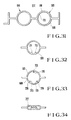
- Figs. 30 and 31 show other embodiments of the present invention in which different structures of the switch 52, especially a movable contact thereof are shown.
- a movable contact 677 made of silicone rubber is disposed through a spacer.
- a fixed contact of a predetermined pattern and its peripheral circuit are printed on an upper surface of a printed circuit board.
- a predetermined window is formed in the spacer so that the fixed contact is exposed upward.
- a pair of cylindrical portions 685 of the movable contacts 677 are disposed immediately above the window. Legs of the switch drive portion 50 are arranged above the cylindrical portions 685.
- the movable contact 677 has band-like conductive portions 687 made of conductive rubber at lower half portions of the pair of cylindrical portions 685, respectively.
- a lower half of each cylindrical portion 685 constitutes a contact portion 689 which is brought into contact with the fixed contact and closes (turns on) it, and an upper half portion thereof constitutes an urged portion 691 which is urged by the switch drive portion 50 and is brought into tight contact with the contact portion 689, respectively.
- a circular space is formed between the urged portion 691 and the contact portion 689 which oppose each other.
- a band-like projection 695 projects from a lower surface (surface opposite to the contact portion 689) of the urged portion 691 of one of the cylindrical portions 685.
- the projection 695 constitutes a welding preventing means 697 for preventing welding of the urged portion 691 when the urged portion 691 is brought into tight contact with the contact portion 689.
- the hammer 41 moves downward along with the pivoting motion of the key 33. That is, the hammer 41 is pivoted about the pin (fulcrum) 45, and the switch drive portion 50 abuts against the urged portion 691 of the movable contact 677 and urges it.
- the urged portion 691 is elastically deformed, and the projection 695 is brought into contact with the opposite surface of the contact portion 689. Therefore, the contact portion 689 is elastically deformed to be brought into contact with the fixed contact and short-circuits it. That is, the switch is turned on.
- the urged portion 691 is not brought into perfect contact with the contact portion 689 because the projection 695 is present. That is, predetermined spaces are formed at both sides of the projection 695, and a contacting surface area is reduced as a whole, thereby preventing welding between the urged portion 691 and the contact portion 689. For this reason, when the key 33 is released, the urged portion 691 instantaneously restores its original shape by a recovering force (elastic force) of the rubber, and substantially at the same time, the contact portion 689 is similarly restored. That is, the response characteristic can be assured when the switch is kept off, and a vibration of the contact portion 689, i.e., a so-called chattering phenomenon which is repetition of ON/OFF can be completely prevented.
- the movable contact 677 Since the movable contact 677 has the pair of cylindrical portions 685, two switches are closed at different timings. Therefore, a difference between the timings is detected to control a volume, an envelop change, a tone color, and the like of a musical tone.
- Fig. 31 shows still another embodiment of the present invention.
- a number of small projections 701 having a saw-tooth like sectional shape are formed on an inner surface of the cylindrical portion 685 of the movable contact 677.
- the projections 701 are projections formed on opposing inner surfaces of both the urged portion 691 and the contact portion 689. When the urged portion 691 is brought into tight contact with the contact portion 689, the projections 701 reduces a contact area and a contact force. Therefore, the projections 701 constitute a welding preventing means.
- Fig. 32 shows still another embodiment of the present invention.
- two projections 711 and 713 are formed on an inner surface of the contact portion 689. Similar to the above embodiment, these projections 711 and 713 reduce the contact area and the contact force. That is, the projections 711 and 713 constitute a welding preventing means.
- Figs. 33 and 34 show still another embodiment of the present invention.
- a projection 721 is formed on an inner surface of the urged portion 691, and two projections 723 and 725 are formed on an inner surface of the contact portion 689.
- These projections 721, 723, and 725 are arranged offset from each other so that relatively large spaces 727 are formed at both sides upon deformation.
- Small bubble-like sealed spaces 729 are formed inside the projections 721, 723, and 725, respectively. Therefore, the urged portion 691 and the contact portion 689 are brought into tight contact with each other and deformed, elastic restoration forces of the projections 721, 723, and 725 are further increased. As a result, restoration forces of both the urged portion 691 and the contact portion 689 can be further increased, and welding therebetween can be prevented almost completely.
- the projections 721, 723, and 725 and the sealed spaces 729 thereof constitute a welding preventing means as a whole.
- the movable contact is formed to be cylindrical.
- the movable contact may be partially notched.
- the welding preventing means is not limited to the projections or the recesses in the above embodiments.
- at least one of the opposing surfaces of the urged portion and the contact portion may be coated with Teflon or the like. That is, welding is prevented by reducing an adhesion force of rubber.
- a nonadhesive material is not limited to Teflon but other resin materials or the like may be used.
- the above band-like projection may be formed by a material other than rubber, e.g., a metal wire.
- FIGs. 35 and 36 show still another modification of the engaging portion of the present invention.
- the same parts as in Fig. 3 denote the same reference numerals in Figs. 35 and 36.
- a rubber vibration damping portion 797 of the actuator portion 47 formed in the hammer 41 is formed such that a right end portion thereof reaches sides of a proximal end portion 62 and an abutting portion 63, i.e., extends vertically.
- a member removal preventing portion 798 is constituted by the vibration damping portion 797. Therefore, if a projection of the key 33 abruptly abuts against the member removal preventing portion 798 when it is removed from the fulcrum of the key 33, an impact force can be damped and reduced, thereby preventing a damage to the projection 40 of the key 33 made of a synthetic resin material.
- Figs. 37 and 38 show still another modification of the engaging portion of the present invention.
- the same parts as in Fig. 3 denote the same reference numerals in Figs. 37 and 38.
- a side wall at the projection 40 of the switch drive portion 50 of the hammer 41 is formed of resin by outserting to serve as an abutting portion 790. That is, when the hammer 41 moves to the right in Fig. 37 by a predetermined distance, the abutting portion 790 abuts against a peripheral portion 791 to the right of the slit 60 of the frame 31, thereby regulating movement of the hammer 41. Therefore, the peripheral portion 791 constitutes a regulating portion. As a result, in addition to the above effect, the number of members can be reduced since the members can be commonly used.
- the hammer 41 can be made smaller by embedding a metal member having larger mass than that of the core metal at a proper position such as Q.
- the stopper portion is provided vertically along the side walls of the key so as to regulate movement of the key in a transverse direction.
- a guide portion may be extended downward from the key, and stopper members for regulating movement of the key in the transverse direction may be provided at both sides of the guide member.
Landscapes
- Physics & Mathematics (AREA)
- Engineering & Computer Science (AREA)
- Acoustics & Sound (AREA)
- Multimedia (AREA)
- Electrophonic Musical Instruments (AREA)
Claims (53)
- Clavier pour instrument de mesure électronique, comportant :- un ensemble de touches (33), chacune desquelles pivote par rapport à un premier axe de pivotement (35);- un ensemble d'éléments formant poids (41) correspondant auxdites touches (33) respectivement, chacun desquels est positionné en-dessous de chacune des clés correspondantes (33) et pivote par rapport à un second axe de pivotement (45) en coopération avec la touche correspondante (33) pour donner à la touche correspondante (33) l'inertie du poids (41) lorsque la touche correspondante (33) est enfoncée; et- un ensemble de moyens de sollicitation correspondant auxdites touches (33) respectivement, chacun desquels est constitué par un élément commun formant ressort (61) qui sollicite ledit élément de poids correspondant (41) et ladite touche correspondante (33) vers un état initial,caractérisé par
ledit élément de ressort commun (61) est réalisé sous la forme d'une plaque de ressort et est disposé entre ledit poids correspondant (41) et ladite touche correspondante (33). - Clavier selon la revendication 1, dans lequel chacun des poids (41) et chacun des éléments de sollicitation sont positionnés entre les parois latérales intérieures de la touche correspondante (33).
- Clavier selon la revendication 1, dans lequel chacune desdites touches (33) a un point d'application pour faire pivoter un desdits poids correspondants (41) dans le même sens de rotation que le sens de pivotement de chacune desdites touches (33) lorsque chaque touche (33) est enfoncée.
- Clavier selon l'une quelconque des revendications précédentes, dans lequel le second axe de pivotement (45) est disposé plus près d'un côté frontal de ladite touche (33) que ne l'est le premier axe de pivotement (35).
- Clavier selon l'une quelconque des revendications précédentes, dans lequel les premier et second axes de pivotement (35, 45) sont disposés dans un même plan.
- Clavier selon la revendication 3, dans lequel le point d'application est prévu d'un côté où le centre de gravité dudit poids (41) est disposé par rapport audit second axe de pivotement (45) dudit poids (41).
- Clavier selon l'une quelconque des revendications 1 à 6, comprenant en outre une partie d'entraînement de commutateur (50) prévue dans ledit poids (41), un interrupteur de réponse de toucher (52) prévu en association avec ladite partie d'entraînement de commutateur (50), et un circuit de commande, commandé par l'actionnement dudit commutateur (52), pour commander la production d'un son musical, et dans lequel, lorsque le poids (41) pivote en conformité avec une action d'enfoncement de ladite touche (33), ladite partie d'entraînement de commutateur (50) actionne ledit commutateur (52) et ledit commutateur (52) commande ledit circuit de commande.
- Clavier selon la revendication 7, dans lequel ledit commutateur (52) est un commutateur à deux positions.
- Clavier selon la revendication 7 ou la revendication 8, dans lequel ledit commutateur (52) comporte un contact fixe prévu sur une carte à circuit imprimé (54) et un élément mobile ayant un contact mobile (56, 58) disposé pour se trouver en face dudit contact fixe avec un espace prédéterminé, et ledit élément mobile comporte une partie sollicitée d'un matériau flexible.
- Clavier selon la revendication 7 ou la revendication 8, dans lequel ledit commutateur (52) comporte deux contacts fixes formé sur une carte à circuit imprimé (54) et un élément mobile ayant un contact mobile (56, 58) constituant deux parties de commutateur disposées de façon à se trouver en face dudit contact fixe à une distance prédéterminée et ledit élément mobile comporte deux parties sollicitées de forme cylindrique d'un matériau flexible et un élément de couplage pour coupler lesdites parties sollicitées cylindriques auxdits deux contacts fixes.
- Clavier selon la revendication 10, dans lequel ledit commutateur (52) comporte un commutateur à deux positions, qui est fermé à des intervalles de temps différents.
- Clavier selon la revendication 11, dans lequel des moyens empêchant le soudage (697) sont prévus dans une desdites parties sollicitées constituant la partie de commutateur qui est fermée en premier, des deux dites parties de commutateur.
- Clavier selon la revendication 12, dans lequel lesdits moyens empêchant le soudage consistent en une dépression ou une saillie (95, 701, 711, 713, 721, 723, 725).
- Clavier selon l'une quelconque des revendications précédentes, dans lequel un mécanisme formant coussin (145) est prévu entre le point d'application sur ladite touche (33) et ledit poids (41).
- Clavier selon la revendication 14, dans lequel ledit élément formant coussin (145) comporte une première partie d'activateur (147), qui est tout d'abord déformée élastiquement lors de l'enfoncement de la touche (33), et une seconde partie d'activateur (149) déformée élastiquement après la déformation de la première partie d'activateur (145) d'une quantité prédéterminée et ayant un module d'élasticité qui est plus grand que le module d'élasticité de ladite première partie d'activateur (147).
- Clavier selon la revendication 15, dans lequel au moins une desdites parties de premier et second activateurs est constituée par un ensemble d'éléments élastiques (247, 249, 251) présentant des modules d'élasticité différents.
- Clavier selon la revendication 14, dans lequel ledit mécanisme formant coussin (145) accumule, sous forme d'énergie élastique, dans une période initiale de l'enfoncement de la touche, une composante prédéterminée d'une force appliquée au point d'application à partir de ladite touche vers ledit poids (41) et accumule, sous forme d'énergie élastique pendant et/ou après l'enfoncement de la touche, une partie des composantes de la force appliquée de ladite touche (33) vers ledit poids (41) qui est inférieure à la force appliquée pendant la période initiale d'enfoncement de la touche.
- Clavier selon la revendication 17, dans lequel ledit mécanisme formant coussin comporte un activateur (265) fixé à l'un desdits éléments formant touche (33) et poids (41) et venant en butée contre l'élément restant, ledit activateur (265) est soumis à une déformation de flexion pour accumuler l'énergie élastique et le moment de flexion agissant sur ledit activateur (265) est important dans la période initiale de l'enfoncement de la touche et est plus petit que le moment de flexion de la période initiale de l'enfoncement de la touche pendant et/ou après l'enfoncement de la touche.
- Clavier selon la revendication 18, dans lequel la rigidité à la flexion de la partie en butée dudit activateur (265) au cours de la période initiale de l'enfoncement de la touche est inférieure à la rigidité à la flexion agissant sur celle-ci pendant et/ou après l'enfoncement de la touche.
- Clavier selon la revendication 18, dans lequel la section de la partie en butée dudit activateur (265) au cours de la période initiale de l'enfoncement de la touche est inférieure à la section correspondante pendant et/ou après l'enfoncement de la touche.
- Clavier selon la revendication 18, dans lequel le module d'élasticité de ladite partie en butée dudit activateur (265) est plus petit que le module d'élasticité de celui-ci pendant et/ou après l'enfoncement de la touche.
- Clavier selon la revendication 17, dans lequel ledit mécanisme formant coussin comporte un activateur (265) fixé à un desdits éléments formant ladite touche (33) et ledit poids (41) et venant en butée contre l'un des deux, ledit activateur (265) est déformé élastiquement pour accumuler l'énergie élastique et le module d'élasticité de la partie en butée au cours de la période initiale de l'enfoncement de la touche est plus grand que le module d'élasticité correspondant pendant et/ou après l'enfoncement de la touche.
- Clavier selon la revendication 14, dans lequel ledit mécanisme formant coussin (245) est constitué par un ensemble de saillies (247, 249, 251), disposées dans le sens longitudinal de ladite touche (33) et ledit ensemble de saillies (247, 249, 251) viennent en butée séquentiellement contre ladite touche conformément au mouvement de pivotement de ladite touche (33).
- Clavier selon la revendication 3, dans lequel ledit ressort (61) consiste en un élément élastique unique agissant à la fois sur ledit poids (41) et ladite touche (33) dans un sens qui est opposé au sens de pivotement de ladite touche (33) et dudit poids (41) lors de l'enfoncement de ladite touche (33).
- Clavier selon la revendication 24, dans lequel les axes de pivotement (35, 45) de ladite touche (33) et dudit poids (41) sont prévus sur un châssis (31) et ledit élément élastique s'étend entre l'axe de pivotement (35) de ladite touche (33) et une partie d'extrémité voisine de l'axe de pivotement (45) dudit poids (41).
- Clavier selon la revendication 25, dans lequel un arrêtoir (83) comportant une partie élastique en saillie (85), qui est dirigée vers l'axe de pivotement (35) de la touche (33) est disposé sur ledit châssis (31) entre les axes de pivotement (35, 45) de ladite touche (33), et dudit poids et, au cours du montage de ladite touche (33), cette dernière, qui coopère avec l'axe de pivotement (35), est poussée dans le sens d'enfoncement de la touche, alors que ladite partie en saillie (85) est déformée élastiquement, de telle sorte qu'on évite ainsi le dégagement de ladite touche (33) de l'axe de pivotement (35).
- Clavier selon la revendication 26, dans lequel ledit arrêtoir (83) est réalisé par déformation par rapport au châssis (31).
- Clavier selon l'une des revendications 25 à 27, dans lequel ledit arrêtoir (83) comporte une seconde partie en saillie (86), qui se dirige vers l'axe de pivotement (45) dudit poids (41) et, lors de l'assemblage de ladite touche (38), ledit poids (41), qui coopère avec le pivot (45), est poussé dans le sens d'enfoncement de la touche (33) alors que ladite seconde partie en saillie (86) est élastiquement déformée, ce qui empêche le dégagement dudit poids (41) à partir de l'axe de pivotement (45).
- Clavier selon la revendication 25, dans lequel ladite touche (33) consiste en un élément creux et l'arrêtoir (83) pour régler une déformation élastique excessive dudit élément élastique (61) est disposé sur ledit châssis (31) entre le pivot (35) de ladite touche (33) et le pivot (45) dudit poids (41), de telle sorte que l'arrêtoir (83) est reçu à l'intérieur de l'élément creux de ladite touche (33).
- Clavier selon la revendication 25, dans lequel l'arrêtoir (83) pour réguler la déformation élastique excessive dudit élément élastique (61), est disposé sur ledit châssis (31) entre l'axe de pivotement (35) de ladite touche (33) et l'axe de pivotement (45) dudit poids (41).
- Clavier selon la revendication 30, dans lequel ledit arrêtoir (83) est disposé de façon à être séparé dudit élément élastique (61) d'une distance prédéterminée lorsque ladite touche (33) n'est pas enfoncée ou est enfoncée.
- Clavier selon la revendication 25, dans lequel ladite touche (33) comporte des moyens s'opposant à son dégagement pour empêcher l'extraction de ladite touche (33) de l'axe de pivotement (35).
- Clavier selon la revendication 32, dans lequel lesdits moyens s'opposant au dégagement comportent une rainure (39p), qui est formée au voisinage de l'extrémité de la partie de l'axe du pivot (35) de ladite touche (33), et dans laquelle une extrémité dudit élément élastique (61) est insérée librement et une partie de régulation de mouvement (81A), qui est formée dans ledit élément élastique (61) et vient buter contre une des parois d'extrémité de ladite rainure (39p) pour réguler le mouvement de ladite touche (33) dans le sens longitudinal de celle-ci.
- Clavier selon la revendication 25, dans lequel ledit élément élastique (61) coopère partiellement avec une partie de ladite touche (33) pour solliciter ladite touche (33) contre ledit axe de pivotement (35), une partie d'extrémité (81) dudit élément élastique (61) d'un côté dudit axe de pivotement (35) de ladite touche (33) peut être déplacé en coulissement dans une rainure (39p) ménagée selon l'axe de pivotement (35) et une partie de maintien (80) est formée à l'autre extrémité dudit élément élastique (61) et s'étend dans le sens longitudinal.
- Clavier selon la revendication 25, dans lequel l'appareil comporte des moyens s'opposant au dégagement pour empêcher le dégagement dudit poids (41) à partir de l'axe de pivotement (45).
- Clavier selon la revendication 35, dans lequel ledit moyen s'opposant au dégagement comporte une rainure (39p) qui est ménagée dans la partie formant extrémité de l'axe de pivotement (35) de ladite touche (33), et dans laquelle une extrémité dudit élément élastique (61) est insérée librement et une partie de régulation de mouvement (81A), qui est formée dans ledit élément élastique (61) et vient en butée contre une paroi d'extrémité de ladite rainure (39p) pour réguler le mouvement de ladite touche (33) dans le sens longitudinal de celle-ci.
- Clavier selon l'une des revendications précédentes, dans lequel le poids (41) est un élément en métal et la surface de celui-ci est partiellement revêtue d'une résine.
- Clavier selon la revendication 37, comportant en outre un arrêtoir (71) pour réguler l'étendue du pivotement dudit poids (41) provoqué par la sollicitation du ressort, et dans lequel ledit poids (41) comporte une partie coopérant avec l'arrêtoir (41Ab) qui coopère avec ledit arrêtoir (71) et une partie d'activateur (41Aa) qui reçoit une force de ladite touche (33), et ladite partie coopérant avec l'arrêtoir (41Ab) sont réalisées dans la résine qui est disposée sur ledit élément de métal.
- Clavier selon la revendication 37 ou la revendication 38, comportant en outre une partie d'entraînement de commutateur (143) prévue sur ledit poids (141), un commutateur de réponse de toucher (52) prévu en association avec ladite partie d'entraînement de commutateur (143) et un circuit de commande, commandé en conformité avec le fonctionnement dudit commutateur (52) pour contrôler la production d'un son musical, et dans lequel, lorsque ledit poids (141) pivote en conformité avec l'enfoncement de la touche (33), ladite partie d'entraînement de commutateur (143) actionne ledit commutateur (52) pour commander ledit circuit de commande et au moins une partie d'extrémité (153), qui coopère avec l'axe de pivotement (45) dudit poids (41) et la partie d'activateur (145) qui reçoit une force de ladite touche et ladite partie d'entraînement (153) sont formées au moyen de la résine qui recouvre ledit élément de métal.
- Clavier selon la revendication 38, dans lequel ledit poids (41) comporte une partie de guidage (41Aa), qui pivote sur un châssis (31) lors de l'enfoncement de ladite couche (33), ladite partie de guidage étant formée au moyen de la résine qui recouvre l'élément de métal.
- Clavier selon la revendication 25, comportant en outre un arrêtoir (71) pour réguler l'importance du pivotement dudit élément formant poids (141) provoqué par la sollicitation du ressort, et dans lequel ledit poids (141) est un élément en métal, et un élément venant coopérer avec l'arrêtoir (144A), qui coopère avec ledit arrêtoir (71) dudit élément formant poids (41), une partie d'activateur (145), qui reçoit une force de ladite touche et une partie d'extrémité (153) dudit élément formant poids (141), avec lequel ledit élément élastique (61) coopère, sont réalisées dans la résine qui constitue le revêtement dudit élément en métal.
- Clavier selon la revendication 38, dans lequel une partie de guidage d'insertion (41A) dudit poids pour assurer le guidage en insertion dans un espace (66) ménagé dans un châssis (31) au cours du montage, est réalisée au moyen de la résine qui recouvre ledit élément de métal.
- Clavier selon la revendication 3, dans lequel un second matériau ayant une masse importante est noyé dans ledit poids (41).
- Clavier selon l'une quelconque des revendications précédentes, comportant en outre des moyens formant coussin pour réduire la force d'impact produite lorsque ledit poids (41) vient frapper contre ladite touche (33) au cours du retour dudit poids (41) vers l'état initial sous l'action d'une force de sollicitation d'un ressort au cours du relâchement de ladite touche (33).
- Clavier selon la revendication 44, dans lequel lesdits moyens formant coussin comportent des pièces en saillie (521, 523), qui se prolongent vers le bas à partir d'une surface inférieure de ladite touche (33), de telle sorte que l'intervalle existant entre elles augmente progressivement vers le bas, et ledit poids (41) vient partiellement en butée contre les parois internes desdites pièces en saillie (521, 523).
- Clavier selon la revendication 45, dans lequel les pièces en saillie (521, 523) sont disposées dans le sens longitudinal de ladite touche (33), sous forme d'un ensemble de paires.
- Clavier selon la revendication 45 ou la revendication 46, dans lequel chacune des pièces en saillie (521, 523) est réalisée en un matériau ayant un module d'élasticité qui est plus petit que le module d'élasticité de ladite touche (33).
- Clavier selon l'une des revendications 45 à 47, dans lequel des petites pièces (525, 527) plus petites que lesdites pièces en saillie (521, 523) sont disposées entre lesdites pièces en saillie (521, 523).
- Clavier selon l'une des revendications précédentes, dans lequel des moyens de régulation (651) pour réguler le mouvement de ladite touche (33) dans le sens transversal de celle-ci, sont prévus du côté avant de ladite touche (33).
- Clavier selon la revendication 49, dans lequel lesdits moyens de régulation (651) sont constitués par un arrêtoir (641) qui s'étend verticalement selon les deux parois latérales de ladite touche (33).
- Clavier selon l'une des revendications précédentes, dans lequel ladite touche (33) comporte une saillie (641) qui s'étend vers le bas, les axes de pivotement (35, 45) de ladite touche (33) et dudit poids (41) sont prévus sur un châssis (31) et une partie empêchant leur extraction (65) est prévue pour venir en butée contre ladite saillie (641), ladite partie empêchant le dégagement (65) étant supportée par ledit châssis (31), de telle sorte que ladite saillie (641) coopère avec ladite partie empêchant le dégagement d'un élément (65) lorsque ladite touche (33) est déplacée dans une direction éloignée par rapport à l'axe de pivotement (35), ce qui a pour effet d'empêcher le dégagement de ladite touche (33) ou dudit poids (41) de l'axe de pivotement (45).
- Clavier selon la revendication 51, dans lequel ladite partie qui s'oppose à l'extraction ou au dégagement d'un élément (65), est prévue sur l'élément formant poids (41).
- Clavier selon la revendication 52, dans lequel ladite partie s'opposant au dégagement d'un élément (65) est prévue sur une partie d'activateur dudit élément formant poids (41).
Applications Claiming Priority (28)
| Application Number | Priority Date | Filing Date | Title |
|---|---|---|---|
| JP238828/86 | 1986-10-06 | ||
| JP61238828A JPS6391694A (ja) | 1986-10-06 | 1986-10-06 | 電子楽器の鍵盤装置 |
| JP250216/86 | 1986-10-20 | ||
| JP161312/86 | 1986-10-20 | ||
| JP61250216A JP2508028B2 (ja) | 1986-10-20 | 1986-10-20 | 電子楽器の鍵盤装置 |
| JP1986161312U JPH071679Y2 (ja) | 1986-10-20 | 1986-10-20 | 電子楽器のスイツチ装置 |
| JP260091/86 | 1986-10-30 | ||
| JP61260091A JP2725253B2 (ja) | 1986-10-30 | 1986-10-30 | 電子楽器の鍵盤装置 |
| JP61273230A JPS63125996A (ja) | 1986-11-17 | 1986-11-17 | 電子楽器の鍵盤装置 |
| JP61273229A JP2775729B2 (ja) | 1986-11-17 | 1986-11-17 | 電子楽器の鍵盤装置 |
| JP1986176480U JPH0713034Y2 (ja) | 1986-11-17 | 1986-11-17 | 電子楽器の鍵盤装置 |
| JP176480/86 | 1986-11-17 | ||
| JP273228/86 | 1986-11-17 | ||
| JP61273226A JP2508033B2 (ja) | 1986-11-17 | 1986-11-17 | 電子楽器の鍵盤装置 |
| JP273226/86 | 1986-11-17 | ||
| JP61273228A JP2718024B2 (ja) | 1986-11-17 | 1986-11-17 | 電子楽器の鍵盤装置 |
| JP176479/86 | 1986-11-17 | ||
| JP273227/86 | 1986-11-17 | ||
| JP273225/86 | 1986-11-17 | ||
| JP1986176479U JPH0713035Y2 (ja) | 1986-11-17 | 1986-11-17 | 電子楽器の鍵盤装置 |
| JP61273227A JP2720432B2 (ja) | 1986-11-17 | 1986-11-17 | 電子楽器の鍵盤装置 |
| JP273230/86 | 1986-11-17 | ||
| JP61273225A JP2518232B2 (ja) | 1986-11-17 | 1986-11-17 | 電子楽器の鍵盤装置 |
| JP273229/86 | 1986-11-17 | ||
| JP17715986U JPH05954Y2 (fr) | 1986-11-18 | 1986-11-18 | |
| JP61274940A JPH0640261B2 (ja) | 1986-11-18 | 1986-11-18 | 電子楽器の鍵盤装置 |
| JP274940/86 | 1986-11-18 | ||
| JP177159/86 | 1986-11-18 |
Publications (3)
| Publication Number | Publication Date |
|---|---|
| EP0263494A2 EP0263494A2 (fr) | 1988-04-13 |
| EP0263494A3 EP0263494A3 (en) | 1990-02-07 |
| EP0263494B1 true EP0263494B1 (fr) | 1994-01-26 |
Family
ID=27584909
Family Applications (1)
| Application Number | Title | Priority Date | Filing Date |
|---|---|---|---|
| EP87114593A Expired - Lifetime EP0263494B1 (fr) | 1986-10-06 | 1987-10-06 | Clavier pour instrument de musique électronique |
Country Status (7)
| Country | Link |
|---|---|
| US (1) | US4901614A (fr) |
| EP (1) | EP0263494B1 (fr) |
| KR (1) | KR920000795B1 (fr) |
| CN (1) | CN1014941B (fr) |
| DE (1) | DE3788919T2 (fr) |
| HK (1) | HK133995A (fr) |
| SG (1) | SG21295G (fr) |
Families Citing this family (35)
| Publication number | Priority date | Publication date | Assignee | Title |
|---|---|---|---|---|
| KR900005374A (ko) * | 1988-09-19 | 1990-04-14 | 이효익 | 전자 악기용 건반 |
| JPH02149893A (ja) * | 1988-11-30 | 1990-06-08 | Kawai Musical Instr Mfg Co Ltd | 電子楽器の鍵盤装置 |
| DE3905646C1 (fr) * | 1989-02-24 | 1990-08-02 | Wersi Gmbh & Co, 5401 Halsenbach, De | |
| US5243125A (en) * | 1991-03-22 | 1993-09-07 | Kabushiki Kaisha Kawai Gakki Seisakusho | Keyboard apparatus for electronic musical instrument having cooperating jacks and hammers |
| JP2528588Y2 (ja) * | 1991-04-24 | 1997-03-12 | 株式会社河合楽器製作所 | 電子楽器の鍵盤装置 |
| JP2891080B2 (ja) * | 1993-12-24 | 1999-05-17 | ヤマハ株式会社 | 鍵盤装置 |
| US6005178A (en) * | 1994-03-24 | 1999-12-21 | Yamaha Corporation | Electronic musical instrument simulating acoustic piano keytouch characteristics |
| US5895875A (en) * | 1994-03-24 | 1999-04-20 | Yamaha Corporation | Keyboard assembly for electronic musical instrument |
| IT235571Y1 (it) * | 1995-02-20 | 2000-07-12 | Fatar Srl | Perfezionamenti alle tastiere per pianoforti elettronici e simili. |
| JP3221283B2 (ja) * | 1995-05-22 | 2001-10-22 | ヤマハ株式会社 | 鍵盤装置 |
| JP2917859B2 (ja) * | 1995-05-22 | 1999-07-12 | ヤマハ株式会社 | 鍵盤装置 |
| JP2917863B2 (ja) * | 1995-06-20 | 1999-07-12 | ヤマハ株式会社 | 電子楽器の鍵盤装置およびその質量体製造方法 |
| US5821443A (en) * | 1996-01-29 | 1998-10-13 | Yamaha Corporation | Keyboard apparatus with an improved mass member support system |
| JP3104611B2 (ja) * | 1996-03-07 | 2000-10-30 | ヤマハ株式会社 | 鍵盤装置 |
| JP2929994B2 (ja) * | 1996-03-12 | 1999-08-03 | ヤマハ株式会社 | 楽器用鍵盤装置 |
| JPH10171443A (ja) * | 1996-12-16 | 1998-06-26 | Yamaha Corp | 鍵盤装置 |
| JP2003248482A (ja) * | 2002-02-25 | 2003-09-05 | Kawai Musical Instr Mfg Co Ltd | 操作検出スイッチ、楽器およびパラメータ決定用プログラム |
| US6930234B2 (en) | 2002-06-19 | 2005-08-16 | Lanny Davis | Adjustable keyboard apparatus and method |
| US6875913B2 (en) | 2002-10-30 | 2005-04-05 | David N. Bubar | Collapsible musical keyboard |
| JP4396664B2 (ja) * | 2005-07-21 | 2010-01-13 | ヤマハ株式会社 | 鍵盤装置及び該鍵盤装置の製造方法 |
| US7678989B2 (en) * | 2006-10-26 | 2010-03-16 | Magnekey | Use of constant force spring in keyboard assembly |
| JP5168968B2 (ja) * | 2007-03-23 | 2013-03-27 | ヤマハ株式会社 | 鍵駆動装置付き電子鍵盤楽器 |
| JP4946629B2 (ja) * | 2007-05-28 | 2012-06-06 | ヤマハ株式会社 | 電子楽器の鍵盤装置 |
| US7750222B2 (en) * | 2007-09-21 | 2010-07-06 | Yamaha Corporation | Keyboard apparatus of electronic musical instrument |
| US7825312B2 (en) * | 2008-02-27 | 2010-11-02 | Steinway Musical Instruments, Inc. | Pianos playable in acoustic and silent modes |
| US20090282962A1 (en) * | 2008-05-13 | 2009-11-19 | Steinway Musical Instruments, Inc. | Piano With Key Movement Detection System |
| US8148620B2 (en) * | 2009-04-24 | 2012-04-03 | Steinway Musical Instruments, Inc. | Hammer stoppers and use thereof in pianos playable in acoustic and silent modes |
| US8541673B2 (en) | 2009-04-24 | 2013-09-24 | Steinway Musical Instruments, Inc. | Hammer stoppers for pianos having acoustic and silent modes |
| JP5624772B2 (ja) * | 2010-01-25 | 2014-11-12 | 株式会社河合楽器製作所 | 電子鍵盤楽器の鍵盤装置 |
| JP5974553B2 (ja) | 2012-03-12 | 2016-08-23 | ヤマハ株式会社 | 鍵盤装置 |
| JP6747134B2 (ja) * | 2016-07-22 | 2020-08-26 | ヤマハ株式会社 | 鍵盤装置 |
| FR3084200B1 (fr) * | 2018-07-18 | 2021-06-18 | Expressive | Controleur haptique ameliore |
| FR3106017B1 (fr) | 2020-01-07 | 2024-02-09 | Adele H | Piano électronique |
| JP7508821B2 (ja) * | 2020-03-23 | 2024-07-02 | ヤマハ株式会社 | 鍵盤装置の鍵の支持構造、鍵盤装置及び電子楽器 |
| CN212750341U (zh) * | 2020-07-24 | 2021-03-19 | 得理乐器(珠海)有限公司 | 一种弹簧键盘 |
Family Cites Families (9)
| Publication number | Priority date | Publication date | Assignee | Title |
|---|---|---|---|---|
| US2996942A (en) * | 1956-05-15 | 1961-08-22 | Harold A Jewett | Keyboards and accessories |
| US3251923A (en) * | 1962-05-29 | 1966-05-17 | Pratt Read & Co Inc | Keyboard operated electrical switches |
| JPS4815866B1 (fr) * | 1968-08-13 | 1973-05-17 | ||
| US4079651A (en) * | 1976-01-30 | 1978-03-21 | Nippon Gakki Seizo Kabushiki Kaisha | Touch response sensor for an electronic musical instrument |
| US4375179A (en) * | 1980-10-27 | 1983-03-01 | The Wurlitzer Company | Action for electronic piano |
| GB2112197B (en) * | 1981-12-24 | 1985-12-04 | Casio Computer Co Ltd | Providing touch response in electronic instruments |
| US4562764A (en) * | 1984-06-08 | 1986-01-07 | Kurzweil Music Systems, Inc. | Electronic musical performance |
| CN86101312A (zh) * | 1985-02-12 | 1986-10-22 | 日本乐器制造株式会社 | 电子乐器键板开关装置 |
| US4679477A (en) * | 1985-06-20 | 1987-07-14 | Charles Monte | Percussive action silent electronic keyboard |
-
1987
- 1987-10-05 US US07/105,188 patent/US4901614A/en not_active Expired - Lifetime
- 1987-10-06 EP EP87114593A patent/EP0263494B1/fr not_active Expired - Lifetime
- 1987-10-06 CN CN87107833A patent/CN1014941B/zh not_active Expired
- 1987-10-06 DE DE3788919T patent/DE3788919T2/de not_active Expired - Fee Related
- 1987-10-06 KR KR1019870011161A patent/KR920000795B1/ko not_active Expired
-
1995
- 1995-02-09 SG SG21295A patent/SG21295G/en unknown
- 1995-08-24 HK HK133995A patent/HK133995A/en not_active IP Right Cessation
Also Published As
| Publication number | Publication date |
|---|---|
| EP0263494A2 (fr) | 1988-04-13 |
| KR880005557A (ko) | 1988-06-29 |
| CN87107833A (zh) | 1988-09-21 |
| DE3788919T2 (de) | 1994-05-26 |
| SG21295G (en) | 1995-08-18 |
| US4901614A (en) | 1990-02-20 |
| KR920000795B1 (ko) | 1992-01-23 |
| EP0263494A3 (en) | 1990-02-07 |
| CN1014941B (zh) | 1991-11-27 |
| HK133995A (en) | 1995-09-01 |
| DE3788919D1 (de) | 1994-03-10 |
Similar Documents
| Publication | Publication Date | Title |
|---|---|---|
| US4901614A (en) | Keyboard apparatus of electronic musical instrument | |
| US5574241A (en) | Keyboard apparatus with common stopper for key and hammer | |
| US5719347A (en) | Keyboard apparatus for electronic musical instrument with key depression detection unit | |
| US4562764A (en) | Electronic musical performance | |
| US5932825A (en) | Keyboard apparatus with white keys and black keys having substantially the same action members | |
| US4476769A (en) | Keyboard apparatus in electronic musical instrument | |
| US6075213A (en) | Drive unit structure for keyboard assemblies | |
| US4856407A (en) | Action mechanism for a keyboard of an electronic piano | |
| JP3624786B2 (ja) | 鍵盤装置 | |
| JP3891440B2 (ja) | 鍵盤装置 | |
| JP4224943B2 (ja) | 鍵盤装置 | |
| JPH0922288A (ja) | 電子楽器の鍵盤装置 | |
| CN106023955B (zh) | 支撑组件和键盘设备 | |
| JP2775729B2 (ja) | 電子楽器の鍵盤装置 | |
| JP2718024B2 (ja) | 電子楽器の鍵盤装置 | |
| JPH05954Y2 (fr) | ||
| JP2720432B2 (ja) | 電子楽器の鍵盤装置 | |
| JP3601113B2 (ja) | 鍵盤装置 | |
| JPS6410077B2 (fr) | ||
| JP3938157B2 (ja) | 鍵盤装置 | |
| JP2508033B2 (ja) | 電子楽器の鍵盤装置 | |
| JPH0121356Y2 (fr) | ||
| JPH0640261B2 (ja) | 電子楽器の鍵盤装置 | |
| JP3550669B2 (ja) | 鍵盤装置 | |
| JPH0713035Y2 (ja) | 電子楽器の鍵盤装置 |
Legal Events
| Date | Code | Title | Description |
|---|---|---|---|
| PUAI | Public reference made under article 153(3) epc to a published international application that has entered the european phase |
Free format text: ORIGINAL CODE: 0009012 |
|
| AK | Designated contracting states |
Kind code of ref document: A2 Designated state(s): DE FR GB |
|
| PUAL | Search report despatched |
Free format text: ORIGINAL CODE: 0009013 |
|
| AK | Designated contracting states |
Kind code of ref document: A3 Designated state(s): DE FR GB |
|
| 17P | Request for examination filed |
Effective date: 19900403 |
|
| 17Q | First examination report despatched |
Effective date: 19910711 |
|
| GRAA | (expected) grant |
Free format text: ORIGINAL CODE: 0009210 |
|
| AK | Designated contracting states |
Kind code of ref document: B1 Designated state(s): DE FR GB |
|
| REF | Corresponds to: |
Ref document number: 3788919 Country of ref document: DE Date of ref document: 19940310 |
|
| ET | Fr: translation filed | ||
| PLBE | No opposition filed within time limit |
Free format text: ORIGINAL CODE: 0009261 |
|
| STAA | Information on the status of an ep patent application or granted ep patent |
Free format text: STATUS: NO OPPOSITION FILED WITHIN TIME LIMIT |
|
| 26N | No opposition filed | ||
| REG | Reference to a national code |
Ref country code: GB Ref legal event code: IF02 |
|
| PGFP | Annual fee paid to national office [announced via postgrant information from national office to epo] |
Ref country code: DE Payment date: 20021011 Year of fee payment: 16 |
|
| PGFP | Annual fee paid to national office [announced via postgrant information from national office to epo] |
Ref country code: FR Payment date: 20031003 Year of fee payment: 17 |
|
| PG25 | Lapsed in a contracting state [announced via postgrant information from national office to epo] |
Ref country code: DE Free format text: LAPSE BECAUSE OF NON-PAYMENT OF DUE FEES Effective date: 20040501 |
|
| PG25 | Lapsed in a contracting state [announced via postgrant information from national office to epo] |
Ref country code: FR Free format text: LAPSE BECAUSE OF NON-PAYMENT OF DUE FEES Effective date: 20050630 |
|
| REG | Reference to a national code |
Ref country code: FR Ref legal event code: ST |
|
| PGFP | Annual fee paid to national office [announced via postgrant information from national office to epo] |
Ref country code: GB Payment date: 20061004 Year of fee payment: 20 |
|
| REG | Reference to a national code |
Ref country code: GB Ref legal event code: PE20 |
|
| PG25 | Lapsed in a contracting state [announced via postgrant information from national office to epo] |
Ref country code: GB Free format text: LAPSE BECAUSE OF EXPIRATION OF PROTECTION Effective date: 20071005 |