EP0263534A2 - Support pour installation électrique - Google Patents
Support pour installation électrique Download PDFInfo
- Publication number
- EP0263534A2 EP0263534A2 EP87115081A EP87115081A EP0263534A2 EP 0263534 A2 EP0263534 A2 EP 0263534A2 EP 87115081 A EP87115081 A EP 87115081A EP 87115081 A EP87115081 A EP 87115081A EP 0263534 A2 EP0263534 A2 EP 0263534A2
- Authority
- EP
- European Patent Office
- Prior art keywords
- housing
- connection
- connectors
- subrack
- connection connectors
- Prior art date
- Legal status (The legal status is an assumption and is not a legal conclusion. Google has not performed a legal analysis and makes no representation as to the accuracy of the status listed.)
- Granted
Links
Images

Classifications
-
- H—ELECTRICITY
- H05—ELECTRIC TECHNIQUES NOT OTHERWISE PROVIDED FOR
- H05K—PRINTED CIRCUITS; CASINGS OR CONSTRUCTIONAL DETAILS OF ELECTRIC APPARATUS; MANUFACTURE OF ASSEMBLAGES OF ELECTRICAL COMPONENTS
- H05K7/00—Constructional details common to different types of electric apparatus
- H05K7/14—Mounting supporting structure in casing or on frame or rack
- H05K7/1438—Back panels or connecting means therefor; Terminals; Coding means to avoid wrong insertion
- H05K7/1447—External wirings; Wiring ducts; Laying cables
- H05K7/1449—External wirings; Wiring ducts; Laying cables with connections to the back board
-
- H—ELECTRICITY
- H05—ELECTRIC TECHNIQUES NOT OTHERWISE PROVIDED FOR
- H05K—PRINTED CIRCUITS; CASINGS OR CONSTRUCTIONAL DETAILS OF ELECTRIC APPARATUS; MANUFACTURE OF ASSEMBLAGES OF ELECTRICAL COMPONENTS
- H05K7/00—Constructional details common to different types of electric apparatus
- H05K7/14—Mounting supporting structure in casing or on frame or rack
- H05K7/16—Mounting supporting structure in casing or on frame or rack on hinges or pivots
Definitions
- the invention relates to a subrack, which is fixedly mounted in the inside of a protective housing and to which contact spring strips for receiving contact pin strips on printed circuit boards and connection connectors for connecting cables leading out of the protective housing are fastened.
- a subrack is a standardized profile frame for installation in a control cabinet or in a separate housing.
- the profile frame is suitable due to a variable, standardized division for accommodating several, in terms of width, also different device modules of the electrical signal transmission technology.
- the device modules are designed without their own housing and essentially consist of a front panel with display devices and controls, a circuit board and a Connection element in the form of a connector part arranged on the back.
- the device assemblies are inserted into the subrack from the front, and their plug connection parts (eg pin headers) can be plugged into complementary plug connection parts (eg female connectors) which are attached to the rear of the subrack.
- the connection elements eg solder pins or "wire-wrap" pins
- the connection elements eg solder pins or "wire-wrap" pins of the plug-in parts of the subrack are partly connected to one another, partly by connecting conductors to externally accessible connection connectors (eg terminal strips).
- the object of the invention is therefore to design a rack with a protective housing of the type described so that a convenient and quick connection of the electrical leads leading to the outside housed in the protective housing or the electronic device units housed therein is possible.
- connection connectors are arranged on the underside of the subrack in at least two rows which are spaced one above the other and which extend parallel to the housing front panel along a line running from one housing side wall to the other, in that the connection connectors of the lower row are opposite the connection connectors the upper row in the direction of the rear wall of the housing are offset to the rear and that the housing base runs at a distance from the bottom row of the connector and is provided in the area below the connector with cable bushings for the connecting cable.
- the connector on the inside of the protective housing fixedly mounted rack so that between these connectors and the housing base in which the cable glands are installed, a wiring space is created, which the respective fitter a simple and convenient connection of the connecting lines to the terminals of the Connection connector allowed.
- the cable bushings are located in the area below the connector in the bottom of the housing, the connecting cables can be routed from the cable bushings to the connectors, so that the individual cables can be separated into those for intrinsically safe and those for non-intrinsically safe circuits what is required in some applications.
- the connection of the cables to the terminals in the connection connector it can be done conveniently from the front of the protective housing; the rear of the housing must not be accessible for the purpose of connecting the lines.
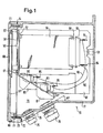
- the subrack 52 shown in FIG. 1 is fixedly mounted in the interior of a protective housing 51 by means of a screw connection 53 and by means of further screw connections installed in the housing side walls (not shown in FIG. 1).
- the protective housing 51 is made of aluminum, for example using the sand casting process.
- Printed circuit boards 54 are inserted into the rack 52 from the front, ie from the side on the left in FIG. 1. Each circuit board 54 is held in guide rails, not shown. At the rear end of each circuit board 54, a contact pin strip 55 is attached, which is inserted into a contact spring strip 56 on the subrack 52. The contact spring strips 56 are screwed to the rack 52. A front plate 57 is attached to the front of each printed circuit board 54, in which measuring or display instruments 58 are fastened, which are analog or digital instruments for displaying a measured value or else can be light-emitting diodes for displaying a respective switching state of the electronic device assembly formed by the components on the printed circuit board 54.
- the measuring or display instruments 58 are connected via connections (not shown) on the printed circuit board 54, via the contact pin strip 55 and the contact spring strip 56 and via lines 59 and 60 to connection connectors 62 and 63, which are designed, for example, as terminal strips.
- connection connectors 62 and 63 which are designed, for example, as terminal strips.
- the lines 59, 60 are connected to "wire-wrap" pins 64 on the rear side of the contact spring strips 56 and to such "wire-wrap" pins 65, 66 on the Back of the connector 62 and 63 attached.
- the front plates 57 are fastened to the subrack 52 with the aid of screws 67.
- a housing front plate 68 forming a cover is attached on the front of the housing 51.
- a viewing window 69 is fitted in this housing front plate 68 in alignment with the area of the subrack 52 which is intended for receiving the printed circuit boards 54.
- This viewing window 69 is preferably made of a polycarbonate, and it is glued to the housing front plate 68.
- the housing front plate 68 has on its lower side a retaining hook 70 which is fastened to the housing front plate 68 by means of a screw 71.
- a bolt 72 is attached to the housing 51, around which a curved section of the holding hook 70 is placed.
- the housing front plate 68 can be opened by loosening a screw 73 attached in the area of the upper side of the housing 51.
- the housing front plate 68 After loosening the screw 73, the housing front plate 68 can be folded down, the bolt 72 forming a fulcrum for the retaining hook 70. Because of the curvature of the retaining hook 70, the housing front plate 68 can be completely removed from the rest of the housing in the folded-down position.
- a seal 74 is inserted between the housing front plate 68 and the rest of the housing.
- the connecting cables leading into the housing 51 are guided through a plurality of cable bushings 75, 76. These cable bushings are watertight, so that a hermetic seal against moisture and dust is also guaranteed at this point.
- the housing base 77 runs in the region of the cable bushings 75, 76 at an angle of 30 ° downwards to the lower edge of the housing front plate 68.
- the connection connectors 62, 63 are arranged on the underside of the rack 52 in two rows one above the other which are parallel to one another Front housing plate 68 extend along a line running from one housing side wall to the other.
- the connector connectors 63 of the lower row are offset against the connector connectors 62 of the upper row towards the rear wall of the housing in such a way that an imaginary connecting line between the rows forms an angle of 60 ° with the housing front panel. This also means that the imaginary connecting line of the rows forms an angle of 30 ° with the horizontally running part of the housing base 77.
- two cable bushings are arranged in the part of the housing bottom 77 which runs obliquely downward for each row of the connection connectors 62, 63.
- the cable bushings are also arranged in two rows, which run essentially perpendicularly under the rows of the connector.
- the housing front plate 68 Due to the angling of the housing base 77 in the area the cable bushings 75, 76 and the staggered arrangement of the rows of connection connectors 62, 63, when the housing front plate 68 is removed or folded down, creates an opening 79 at an angle of 60 ° to the front, so that there is enough space for a fitter to carry out the work the cable feedthroughs 75 and 76 can connect the inserted cables to the terminals of the connector 62, 63.
- the space 79 is sufficiently large that separating plates 80, 81 can be attached to the connector between individual groups of terminals, with the aid of which the connector 62, 63 can be divided into areas with intrinsically safe circuits and into areas with non-intrinsically safe circuits.
- the separation of intrinsically safe circuits from non-intrinsically safe circuits also serves the measure of staggering the cable bushings 75 and 76 according to FIG. 2 in the two rows.
- the lines can be spatially separated from one another more easily and can be led without crossings to the regions of the connecting connectors 62, 63 which are separated by the separating plates 80, 81.
- housing base 77 there is an indentation 78 projecting towards the interior of the housing, which facilitates the fastening of the cable bushings in the housing base 77.
- the angling of the housing base 77 in the area of the housing bushings 75 and 76 and the staggered arrangement of these cable guides 75, 76 has the advantage that the insertion of the connecting cable and thus the installation of the protective housing is made considerably easier.
Landscapes
- Engineering & Computer Science (AREA)
- Microelectronics & Electronic Packaging (AREA)
- Connector Housings Or Holding Contact Members (AREA)
Applications Claiming Priority (4)
| Application Number | Priority Date | Filing Date | Title |
|---|---|---|---|
| DE3340334 | 1983-11-08 | ||
| DE19833340334 DE3340334A1 (de) | 1983-11-08 | 1983-11-08 | Baugruppentraeger in gestellbauweise |
| DE19838332022 DE8332022U1 (de) | 1983-11-08 | 1983-11-08 | Schutzgehäuse mit einem in seinem Innenraum fest montierten Baugruppenträger |
| DE8332022U | 1983-11-08 |
Related Parent Applications (1)
| Application Number | Title | Priority Date | Filing Date |
|---|---|---|---|
| EP84112803.6 Division | 1984-10-24 |
Publications (3)
| Publication Number | Publication Date |
|---|---|
| EP0263534A2 true EP0263534A2 (fr) | 1988-04-13 |
| EP0263534A3 EP0263534A3 (en) | 1988-09-07 |
| EP0263534B1 EP0263534B1 (fr) | 1991-08-07 |
Family
ID=25815445
Family Applications (2)
| Application Number | Title | Priority Date | Filing Date |
|---|---|---|---|
| EP84112803A Expired EP0147560B1 (fr) | 1983-11-08 | 1984-10-24 | Support pour installation électrique |
| EP87115081A Expired - Lifetime EP0263534B1 (fr) | 1983-11-08 | 1984-10-24 | Support pour installation électrique |
Family Applications Before (1)
| Application Number | Title | Priority Date | Filing Date |
|---|---|---|---|
| EP84112803A Expired EP0147560B1 (fr) | 1983-11-08 | 1984-10-24 | Support pour installation électrique |
Country Status (2)
| Country | Link |
|---|---|
| EP (2) | EP0147560B1 (fr) |
| DE (2) | DE3484906D1 (fr) |
Families Citing this family (2)
| Publication number | Priority date | Publication date | Assignee | Title |
|---|---|---|---|---|
| EP0390790A1 (fr) * | 1987-11-12 | 1990-10-10 | Ascom Hasler AG | Boitier electronique pour service severe |
| DE4237865C2 (de) * | 1992-11-10 | 1996-04-18 | Licentia Gmbh | Baugruppenträger |
Family Cites Families (6)
| Publication number | Priority date | Publication date | Assignee | Title |
|---|---|---|---|---|
| CA918795A (en) * | 1971-05-28 | 1973-01-09 | Bell Canada | Wired equipment shelf |
| DE7336813U (de) * | 1973-10-12 | 1974-06-27 | Licentia Gmbh | Anordnung einer Verdrahtung von in einem Rahmen oder Gehäuse übereinander in einer Schaltungsebene angeordneten Baugruppen |
| DE2609062C2 (de) * | 1976-03-05 | 1983-06-09 | Eckardt Ag, 7000 Stuttgart | Baugruppenträger in Gestellbauweise |
| FR2399183A1 (fr) * | 1977-07-26 | 1979-02-23 | Cit Alcatel | Chassis pour cartes de circuits imprimes |
| DE2813812A1 (de) * | 1978-03-31 | 1979-10-04 | Hartmann & Braun Ag | Anordnung zur aufnahme von einschiebbaren elektrischen oder elektronischen baugruppen |
| US4337499A (en) * | 1980-11-03 | 1982-06-29 | Lockheed Corp | Electronic enclosure and articulated back panel for use therein |
-
1984
- 1984-10-24 DE DE8787115081T patent/DE3484906D1/de not_active Expired - Fee Related
- 1984-10-24 DE DE8484112803T patent/DE3473983D1/de not_active Expired
- 1984-10-24 EP EP84112803A patent/EP0147560B1/fr not_active Expired
- 1984-10-24 EP EP87115081A patent/EP0263534B1/fr not_active Expired - Lifetime
Also Published As
| Publication number | Publication date |
|---|---|
| DE3473983D1 (en) | 1988-10-13 |
| EP0147560B1 (fr) | 1988-09-07 |
| EP0263534A3 (en) | 1988-09-07 |
| EP0147560A2 (fr) | 1985-07-10 |
| DE3484906D1 (de) | 1991-09-12 |
| EP0147560A3 (en) | 1985-12-11 |
| EP0263534B1 (fr) | 1991-08-07 |
Similar Documents
| Publication | Publication Date | Title |
|---|---|---|
| EP0677986B1 (fr) | Elément d'un appareil d'automatisation | |
| EP1383368B1 (fr) | Module pour un appareil électronique, module avec bus de secteur en particulier | |
| DE2414566C2 (de) | Elektrisches Automatiksystem | |
| DE19719507A1 (de) | Gestellrahmen mit Baugruppenträger und Belüftungseinrichtung | |
| DE4437316C2 (de) | Dezentrale Ein/Ausgabebaugruppe für elektronische Steuerungen | |
| EP1006768B1 (fr) | Dispositif bus de secteur | |
| EP0662741B1 (fr) | Appareil de coupure à basse tension | |
| EP0263534B1 (fr) | Support pour installation électrique | |
| EP2622952A1 (fr) | Dispositif pour recevoir des boîtiers modulaires à rail porteur | |
| DE19500068B4 (de) | An einer Platte anbringbarer Verbinder | |
| WO1989004559A1 (fr) | Boitier electronique pour service severe | |
| DE19822564C2 (de) | Elektronikgehäuse | |
| EP1869956B1 (fr) | Dispositif | |
| DE1139894B (de) | Einschubrahmen zur Aufnahme mehrerer Schaltungsplatten fuer Fernmeldeanlagen, insbesondere Fernsprechvermittlungsanlagen | |
| DE3412593C2 (fr) | ||
| DE8332022U1 (de) | Schutzgehäuse mit einem in seinem Innenraum fest montierten Baugruppenträger | |
| DE3628113A1 (de) | Fabrikfertiger schaltschrank | |
| EP0584658A2 (fr) | Répartiteur pour armoires blindées contre les interférences électromagnétiques | |
| DE9312842U1 (de) | Elektrische Baugruppe | |
| EP1869741B1 (fr) | Boite de branchement electrique | |
| DE3209699C2 (de) | Universal-Leiterplatte | |
| DE3808294C2 (fr) | ||
| DE4242320C1 (de) | Vielpolige Steckverbindung aus einem Stecker und mindestens einem Gegenstecker für Leiterplatten | |
| DE2450298B2 (de) | Magazin für elektronische Baugruppen tragende Steckkarten | |
| DE2041805A1 (de) | Deckplatte fuer Gehaeuse mit einschiebbaren Leiterplatten |
Legal Events
| Date | Code | Title | Description |
|---|---|---|---|
| PUAI | Public reference made under article 153(3) epc to a published international application that has entered the european phase |
Free format text: ORIGINAL CODE: 0009012 |
|
| 17P | Request for examination filed |
Effective date: 19871015 |
|
| AC | Divisional application: reference to earlier application |
Ref document number: 147560 Country of ref document: EP |
|
| AK | Designated contracting states |
Kind code of ref document: A2 Designated state(s): CH DE FR GB IT LI NL SE |
|
| PUAL | Search report despatched |
Free format text: ORIGINAL CODE: 0009013 |
|
| AK | Designated contracting states |
Kind code of ref document: A3 Designated state(s): CH DE FR GB IT LI NL SE |
|
| 17Q | First examination report despatched |
Effective date: 19901220 |
|
| GRAA | (expected) grant |
Free format text: ORIGINAL CODE: 0009210 |
|
| ITF | It: translation for a ep patent filed | ||
| AC | Divisional application: reference to earlier application |
Ref document number: 147560 Country of ref document: EP |
|
| AK | Designated contracting states |
Kind code of ref document: B1 Designated state(s): CH DE FR GB IT LI NL SE |
|
| ET | Fr: translation filed | ||
| REF | Corresponds to: |
Ref document number: 3484906 Country of ref document: DE Date of ref document: 19910912 |
|
| GBT | Gb: translation of ep patent filed (gb section 77(6)(a)/1977) | ||
| PLBE | No opposition filed within time limit |
Free format text: ORIGINAL CODE: 0009261 |
|
| STAA | Information on the status of an ep patent application or granted ep patent |
Free format text: STATUS: NO OPPOSITION FILED WITHIN TIME LIMIT |
|
| 26N | No opposition filed | ||
| EAL | Se: european patent in force in sweden |
Ref document number: 87115081.9 |
|
| PGFP | Annual fee paid to national office [announced via postgrant information from national office to epo] |
Ref country code: CH Payment date: 19990915 Year of fee payment: 16 |
|
| PGFP | Annual fee paid to national office [announced via postgrant information from national office to epo] |
Ref country code: SE Payment date: 19990920 Year of fee payment: 16 |
|
| PGFP | Annual fee paid to national office [announced via postgrant information from national office to epo] |
Ref country code: NL Payment date: 19990923 Year of fee payment: 16 |
|
| PGFP | Annual fee paid to national office [announced via postgrant information from national office to epo] |
Ref country code: FR Payment date: 20001013 Year of fee payment: 17 |
|
| PGFP | Annual fee paid to national office [announced via postgrant information from national office to epo] |
Ref country code: DE Payment date: 20001017 Year of fee payment: 17 |
|
| PG25 | Lapsed in a contracting state [announced via postgrant information from national office to epo] |
Ref country code: SE Free format text: THE PATENT HAS BEEN ANNULLED BY A DECISION OF A NATIONAL AUTHORITY Effective date: 20001030 |
|
| PG25 | Lapsed in a contracting state [announced via postgrant information from national office to epo] |
Ref country code: CH Free format text: LAPSE BECAUSE OF NON-PAYMENT OF DUE FEES Effective date: 20001031 Ref country code: LI Free format text: LAPSE BECAUSE OF NON-PAYMENT OF DUE FEES Effective date: 20001031 |
|
| PG25 | Lapsed in a contracting state [announced via postgrant information from national office to epo] |
Ref country code: NL Free format text: LAPSE BECAUSE OF NON-PAYMENT OF DUE FEES Effective date: 20010501 |
|
| REG | Reference to a national code |
Ref country code: CH Ref legal event code: PL |
|
| EUG | Se: european patent has lapsed |
Ref document number: 87115081.9 |
|
| NLV4 | Nl: lapsed or anulled due to non-payment of the annual fee |
Effective date: 20010501 |
|
| PGFP | Annual fee paid to national office [announced via postgrant information from national office to epo] |
Ref country code: GB Payment date: 20010914 Year of fee payment: 18 |
|
| REG | Reference to a national code |
Ref country code: GB Ref legal event code: IF02 |
|
| PG25 | Lapsed in a contracting state [announced via postgrant information from national office to epo] |
Ref country code: FR Free format text: LAPSE BECAUSE OF NON-PAYMENT OF DUE FEES Effective date: 20020628 |
|
| PG25 | Lapsed in a contracting state [announced via postgrant information from national office to epo] |
Ref country code: DE Free format text: LAPSE BECAUSE OF NON-PAYMENT OF DUE FEES Effective date: 20020702 |
|
| REG | Reference to a national code |
Ref country code: FR Ref legal event code: ST |
|
| PG25 | Lapsed in a contracting state [announced via postgrant information from national office to epo] |
Ref country code: GB Free format text: LAPSE BECAUSE OF NON-PAYMENT OF DUE FEES Effective date: 20021024 |
|
| GBPC | Gb: european patent ceased through non-payment of renewal fee |
Effective date: 20021024 |