EP0263576B1 - Compresseur avec soupape de décharge - Google Patents
Compresseur avec soupape de décharge Download PDFInfo
- Publication number
- EP0263576B1 EP0263576B1 EP87305316A EP87305316A EP0263576B1 EP 0263576 B1 EP0263576 B1 EP 0263576B1 EP 87305316 A EP87305316 A EP 87305316A EP 87305316 A EP87305316 A EP 87305316A EP 0263576 B1 EP0263576 B1 EP 0263576B1
- Authority
- EP
- European Patent Office
- Prior art keywords
- valve
- seating surface
- compressor
- valve seating
- cylinder
- Prior art date
- Legal status (The legal status is an assumption and is not a legal conclusion. Google has not performed a legal analysis and makes no representation as to the accuracy of the status listed.)
- Expired - Lifetime
Links
Images


Classifications
-
- F—MECHANICAL ENGINEERING; LIGHTING; HEATING; WEAPONS; BLASTING
- F04—POSITIVE - DISPLACEMENT MACHINES FOR LIQUIDS; PUMPS FOR LIQUIDS OR ELASTIC FLUIDS
- F04B—POSITIVE-DISPLACEMENT MACHINES FOR LIQUIDS; PUMPS
- F04B39/00—Component parts, details, or accessories, of pumps or pumping systems specially adapted for elastic fluids, not otherwise provided for in, or of interest apart from, groups F04B25/00 - F04B37/00
- F04B39/08—Actuation of distribution members
-
- F—MECHANICAL ENGINEERING; LIGHTING; HEATING; WEAPONS; BLASTING
- F04—POSITIVE - DISPLACEMENT MACHINES FOR LIQUIDS; PUMPS FOR LIQUIDS OR ELASTIC FLUIDS
- F04C—ROTARY-PISTON, OR OSCILLATING-PISTON, POSITIVE-DISPLACEMENT MACHINES FOR LIQUIDS; ROTARY-PISTON, OR OSCILLATING-PISTON, POSITIVE-DISPLACEMENT PUMPS
- F04C29/00—Component parts, details or accessories of pumps or pumping installations, not provided for in groups F04C18/00 - F04C28/00
- F04C29/12—Arrangements for admission or discharge of the working fluid, e.g. constructional features of the inlet or outlet
- F04C29/124—Arrangements for admission or discharge of the working fluid, e.g. constructional features of the inlet or outlet with inlet and outlet valves specially adapted for rotary or oscillating piston pumps
- F04C29/126—Arrangements for admission or discharge of the working fluid, e.g. constructional features of the inlet or outlet with inlet and outlet valves specially adapted for rotary or oscillating piston pumps of the non-return type
- F04C29/128—Arrangements for admission or discharge of the working fluid, e.g. constructional features of the inlet or outlet with inlet and outlet valves specially adapted for rotary or oscillating piston pumps of the non-return type of the elastic type, e.g. reed valves
-
- F—MECHANICAL ENGINEERING; LIGHTING; HEATING; WEAPONS; BLASTING
- F04—POSITIVE - DISPLACEMENT MACHINES FOR LIQUIDS; PUMPS FOR LIQUIDS OR ELASTIC FLUIDS
- F04B—POSITIVE-DISPLACEMENT MACHINES FOR LIQUIDS; PUMPS
- F04B39/00—Component parts, details, or accessories, of pumps or pumping systems specially adapted for elastic fluids, not otherwise provided for in, or of interest apart from, groups F04B25/00 - F04B37/00
- F04B39/10—Adaptations or arrangements of distribution members
-
- F—MECHANICAL ENGINEERING; LIGHTING; HEATING; WEAPONS; BLASTING
- F16—ENGINEERING ELEMENTS AND UNITS; GENERAL MEASURES FOR PRODUCING AND MAINTAINING EFFECTIVE FUNCTIONING OF MACHINES OR INSTALLATIONS; THERMAL INSULATION IN GENERAL
- F16K—VALVES; TAPS; COCKS; ACTUATING-FLOATS; DEVICES FOR VENTING OR AERATING
- F16K15/00—Check valves
- F16K15/14—Check valves with flexible valve members
- F16K15/1402—Check valves with flexible valve members having an integral flexible member cooperating with a plurality of seating surfaces
-
- F—MECHANICAL ENGINEERING; LIGHTING; HEATING; WEAPONS; BLASTING
- F16—ENGINEERING ELEMENTS AND UNITS; GENERAL MEASURES FOR PRODUCING AND MAINTAINING EFFECTIVE FUNCTIONING OF MACHINES OR INSTALLATIONS; THERMAL INSULATION IN GENERAL
- F16K—VALVES; TAPS; COCKS; ACTUATING-FLOATS; DEVICES FOR VENTING OR AERATING
- F16K15/00—Check valves
- F16K15/14—Check valves with flexible valve members
- F16K15/144—Check valves with flexible valve members the closure elements being fixed along all or a part of their periphery
- F16K15/145—Check valves with flexible valve members the closure elements being fixed along all or a part of their periphery the closure elements being shaped as a solids of revolution, e.g. cylindrical or conical
-
- Y—GENERAL TAGGING OF NEW TECHNOLOGICAL DEVELOPMENTS; GENERAL TAGGING OF CROSS-SECTIONAL TECHNOLOGIES SPANNING OVER SEVERAL SECTIONS OF THE IPC; TECHNICAL SUBJECTS COVERED BY FORMER USPC CROSS-REFERENCE ART COLLECTIONS [XRACs] AND DIGESTS
- Y10—TECHNICAL SUBJECTS COVERED BY FORMER USPC
- Y10T—TECHNICAL SUBJECTS COVERED BY FORMER US CLASSIFICATION
- Y10T137/00—Fluid handling
- Y10T137/7722—Line condition change responsive valves
- Y10T137/7837—Direct response valves [i.e., check valve type]
- Y10T137/7838—Plural
- Y10T137/7839—Dividing and recombining in a single flow path
- Y10T137/784—Integral resilient member forms plural valves
-
- Y—GENERAL TAGGING OF NEW TECHNOLOGICAL DEVELOPMENTS; GENERAL TAGGING OF CROSS-SECTIONAL TECHNOLOGIES SPANNING OVER SEVERAL SECTIONS OF THE IPC; TECHNICAL SUBJECTS COVERED BY FORMER USPC CROSS-REFERENCE ART COLLECTIONS [XRACs] AND DIGESTS
- Y10—TECHNICAL SUBJECTS COVERED BY FORMER USPC
- Y10T—TECHNICAL SUBJECTS COVERED BY FORMER US CLASSIFICATION
- Y10T137/00—Fluid handling
- Y10T137/7722—Line condition change responsive valves
- Y10T137/7837—Direct response valves [i.e., check valve type]
- Y10T137/7879—Resilient material valve
- Y10T137/7888—With valve member flexing about securement
- Y10T137/7889—Sleeve
-
- Y—GENERAL TAGGING OF NEW TECHNOLOGICAL DEVELOPMENTS; GENERAL TAGGING OF CROSS-SECTIONAL TECHNOLOGIES SPANNING OVER SEVERAL SECTIONS OF THE IPC; TECHNICAL SUBJECTS COVERED BY FORMER USPC CROSS-REFERENCE ART COLLECTIONS [XRACs] AND DIGESTS
- Y10—TECHNICAL SUBJECTS COVERED BY FORMER USPC
- Y10T—TECHNICAL SUBJECTS COVERED BY FORMER US CLASSIFICATION
- Y10T29/00—Metal working
- Y10T29/49—Method of mechanical manufacture
- Y10T29/49229—Prime mover or fluid pump making
- Y10T29/49236—Fluid pump or compressor making
Definitions
- This invention relates to a compressor which has discharge valve means adapted to enhance the coefficient of performance of the compressor.
- a cylinder accommodating a piston or a rotor has an outer surface formed thereon with at least one flat valve seating surface at a predetermined location and also formed therein with outlet holes communicating with a pump working chamber defined between an inner surface of the cylinder and the piston or the rotor, and a discharge valve is arranged over the valve seating surface to close and open the outlet holes.
- the minimum possible thickness of the outer wall of the cylinder should be more than a value corresponding to required yield strength of the compressor. Accordingly, also a portion of the cylinder wall formed with the above valve seating surface has to have a sufficient thickness at least equal to the minimum possible thickness.
- the internal spaces of the outlet holes have a considerably large overall volume, as is the case with a conventional compressor.
- This large internal volume of the outlet holes forms a great part of the dead volume of the compression space of the compressor, i.e. a great part of the clearance volume of the pump working chamber formed at the termination of the compression stroke, resulting in degraded coefficient of performance of the compressor.
- U.S.-A-4668172 which comprises a plurality of arcuately concavely curved grooves 14 circumferentially formed in an outer peripheral surface of the cam ring 2a of the cylinder 2 at locations where outlet holes 10 are radially formed through the cam ring 2a so as to minimize the wall thickness of the above locations, a plurality of annular valve bodies 11 formed by an elastic sheet and received in the respective grooves 14 for urging contact with bottom surfaces 14a of the respective grooves 14 for opening and closing the respective outlet holes 11, a holder member 12 mounted on the outer peripheral surface of the cam ring 2a and supporting the valve bodies 11, and a plurality of stoppers 13 secured to the holder member 12 and located within the respective valve bodies 11 for preventing excessive deformation of the valve bodies 11 away from the outlet holes 10.
- the outlet holes 10 can be greatly reduced in length by forming the arcuate grooves 14 in the outer peripheral surface of the cam ring 2a at locations where the outlet holes 10 are radially formed therethrough, so as to minimize the wall thickness of the above locations, thus minimizing the dead volume formed by the outlet holes 10.
- the entire bottom surfaces 14a of the grooves 14 have to be smoothly finished although just small areas of the bottom surfaces 14a are in contact with the valve body 11.
- ribs 14b are formed between the adjacent grooves 14 so as to reinforce the strength of the peripheral wall of the cam ring 2a, but they interfere with the rotary shaft of the milling cutter inserted into the grooves 14, which makes it impossible to use a small-sized milling cutter capable of forming grooves with the same radius of curvature as that of the valve bodies 11.
- valve bodies 11 are arranged to be strongly forced against the seating surface portions in order to obtain tight contact therebetween, the valve bodies cannot be opened by a suitable pressure force of the compressed gas, resulting in excessive compression of the gas and degraded performance of the compressor.
- the invention provides a compressor having the characterising features of Claim 1.
- the at least one valve seating surface is formed by pressing with a press or by grinding with a grinding tool.
- reference numeral 1 designates a cylindrical casing accommodating therewithin a cylinder 2 which is formed by a cam ring 2a having an inner peripheral camming surface elliptical in cross section, and a front side block 2b and a rear side block 2c closing open opposite end faces of the cam ring 2a, respectively.
- a rotor 4 is rotatably received within the cylinder 2 for rotation in unison with a rotary shaft 3 disposed within the cylinder 2, about an axis thereof.
- the rotor 4 has a plurality of vane slits 5 radially formed therein in circumferetially equidistantly spaced relation to each other in which are slidably fitted vanes 6, respectively.
- the vanes 6 are brought into sliding contact with the inner peripheral camming surface of the cylinder 2 by the action of vane back pressure acting on the respective vanes 6 at their inner end faces as well as a centrifugal force caused by the rotation of the rotor 4 so that the vanes 6 are radially slidably moved within the respective vane slits 5 depending upon the camming surface of the cam ring 2a.
- the respective vanes 6 serve to divide a pair of space chambers A and B within the cylinder 2, which are diametrically separated from each other by the rotor 4, into a plurality of pump working chambers 7.
- a pair of inlet holes 8 are formed in the front side block 2b to communicate pump working chambers 7 on the suction stroke with a suction chamber 40, while a pair of outlet holes 10 are formed in the peripheral wall of the cam ring 2a to communicate pump working chambers 7 on the delivery stroke with a discharge pressure chamber 9.
- Discharge valves 11 are provided on the outer peripheral surface of the cam ring 2a so as to open and close the respective discharge holes 10.
- reference numerals 23 and 24 designate, respectively, a suction port and a discharge port formed in the casing 1, the former communicating via a check valve, not shown, with the suction chamber 40, and the latter with the discharge pressure chamber 9, respectively.
- the volume of the pump working chamber 7 increases to cause refrigerant gas to be drawn through the inlet hole 8 into the pump working chamber 7, during the compression stroke the volume of the pump working chamber 7 decreases to cause the refrigerant gas within the chamber 7 to be compressed, and during the discharge stroke immediately atfer completion of the compression stroke the refrigerant gas thus compressed forces the discharge valves 11 to open to be discharged through the outlet holes 10 into the discharge pressure chamber 9.
- the outlet holes 10 are four in number and radially formed through the cam ring 2a in axially equidistant relation to each other, at each of valve seating surface-forming portions 16 of the outer peripheral surface of the cam ring 2a at diametrically opposite locations.
- the valve seating surface-forming portions 16 each have a flat surface which is formed therein with four grooves 14 which are juxtaposed axially of the cylinder 2 and each circumferentially extend parallel to each other, an arcuate, i.e. arcuately concavely curved bottom surface 14a.
- the outlet holes 10 each open at one end in a deepest portion of the bottom surface 14a of a corresponding one of the grooves 14, and open at the other end in the camming inner peripheral surface of the cylinder 2. The other end of each outlet hole 10 faces a corresponding one of pump working chambers 7 on the compression stroke.
- the outlet holes 10 are each formed in the deepest portion of the bottom surface 14a of the groove 14, i.e., at such a location that the wall thickness of the peripheral wall of the cylinder 2 is the minimum, thereby reducing the substantial length of the outlet hole 10 and hence the dead volume of the internal space thereof.
- Ribs 14b are formed integrally with the valve seating surface-forming portion 16 in a manner separating adjacent ones of the four grooves 14 from each other.
- Each rib 14b has its outer side surface formed with an arcuate recess, as best shown in Fig. 5, for facilitating machining of the cylinder 2 for formation of the grooves 14.
- a rectangular recess may be formed in the outer side surface of each rib 14b.
- the grooves 14 are formed by milling with a milling cutter or by casting. They each have a seating surface 17 formed at a circumferentially central portion (the deepest portion) of the bottom surface 14a thereof.
- the seating surface 17 is in the form of an arcuately concavely curved surface having a radius R1 of curvature almost equal to the radius r of curvature of the valve body 11a.
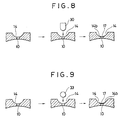
- the seating surfaces 17 are formed by pressing by the use of a press in a manner as described below.
- the punch 30 has its surface 31 located at the circumferentially central portion of the bottom surface 14a of the groove 14, and then load or pressure is applied to the punch 30 so as to form the arcuately concavely curved seating surface 17 at the cirumferentially central portion, as shown in Figs. 7 and 8.
- the amount or length l of pressing is preferably 0.2-0.5 mm.
- the seating surfaces 17 By thus forming the seating surfaces 17 by means of pressing, the seating surfaces 17 can have a radius of curvature almost equal to that of the valve body 11a, as well as a smooth finished surface.
- the seating surfaces 17 may be formed by grinding, as shown in Fig. 9.
- the amount of grinding is preferably 0.2 to 0.3 mm.
- the load or pressure to be applied to the grinding tool 33 can be small and the shank diameter of the tool can also be small. Therefore, the ribs 14b can have a larger width, thus providing increased strength to the cylinder 2.
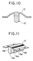
- the discharge valve 11 is formed of an elastic metallic sheet member, which is curved so as to have a C-shaped cross section, as shown in Fig. 5.
- the discharge valve 11 comprises four valve bodies 11 each having a C-shaped cross section, which are juxtaposed to each other at predetermined intervals, and a pair of supporting portions 11b formed integrally with the valve bodies 11a at opposite side edges thereof, i.e. at a side of the valve bodies 11a remote from the bottom surfaces 14a of the grooves 14, and axially extending to connect the valve bodies 11a with each other.
- the valve bodies 11a of the discharge valve 11 are each laid over the valve seating surface 17 of the arcuate bottom surface 14a of its corresponding one of the grooves 14, in tight contact therewith.
- the discharge valve 11 is supportedly engaged with a holder member 12 in such a manner that the paired supporting portions 11b are disposed in urging contact or engagement with opposite lateral side surfaces of a ridge 19 secured on a circumferentially central portion of an inner peripheral surface of the holder member 12.
- the holder member 12 is formed of a metal plate which has an arcuately curved intermediate portion.
- the holder member 12 has two lateral edge portions thereof firmly fixed to the valve seating surface-forming portion 16 of the outer peripheral surface of the cam ring 2a by means of bolts 20.
- valve bodies 11a are mounted on the cam ring 2a by means of the holder member 12 in such a manner that the valve bodies 11a are normally urged in the valve-closing direction by its own elasticity, as shown in Fig. 4, with part of their outer peripheral surfaces disposed in tight contact with the seating surfaces 17 of the respective grooves 14 to keep the respective outlet holes 10 closed in an airtight manner.
- a stopper 13 is arranged within the valve bodies 11a with a certain gap given between the stopper 13 and the valve bodies 11a for restricting excessive deformation of the valve bodies 11a in the valve-opening direction, i.e., toward the holder member 12.
- the stopper 13 is formed of a metal plate having high rigidity and comprises, as shown in Fig. 5, a generally cylindrical member which is formed with four stopper portions 13a circumferentially extending parallel with each other at predetermined intervals, and also with a connecting portion 13b integral with the stopper portions 13a at a side thereof remote from the valve seating surfaces 17 and axially extending to connect the stopper portions 13a with each other.
- the stopper 13 is supported by the holder member 12 with the connecting portion 13b secured, e.q. by brazing to the ridge 19 of the holder member 12.
- the stopper 13′ may be formed integrally with a holder member 12′.
- the holder member 12′ is formed integrally or in one body with four stopper portions 13a′ circumferentially extending parallel with each other at predetermined intervals, and also with a connecting portion 13b′ integral with the stopper portions 13a′ at a side thereof remote from the valve seating surfaces 17 and axially extending to connect the stopper portions 13a′ with each other.
- valve bodies 11a of the discharge valve 11 return to the position shown in Fig. 4 by their own elasticity or force of restitution. In such valve closing state, the valve bodies 11a are positively kept in tight contact with the seating surfaces 17 in an airtight manner since the radius of curvature of the latter is almost equal to that of the former.
Landscapes
- Engineering & Computer Science (AREA)
- General Engineering & Computer Science (AREA)
- Mechanical Engineering (AREA)
- Applications Or Details Of Rotary Compressors (AREA)
- Rotary Pumps (AREA)
- Check Valves (AREA)
Claims (9)
un cylindre (2) ayant une surface interne et une surface périphérique externe, la surface interne ayant une surface périphérique interne courbée en direction circonférentielle et jouant le rôle d'une surface de came,
un dispositif (3, 4, 6) de mise sous pression de fluide, disposé afin qu'il soit mobile dans le cylindre (2), ce dispositif (3, 4, 6) de mise sous pression coopérant avec la surface interne du cylindre (2) afin qu'il délimite au moins une chambre (7) de travail de pompage qui effectue au moins l'aspiration du fluide de compression ou sa compression,
au moins une partie (16) formant une surface de siège de soupape, faisant partie du cylindre (2) et ayant une surface externe,
au moins une cavité (14) formée à la surface externe de ladite partie au moins (16) formant la surface de siège, cette cavité au moins (14) ayant une surface inférieure (14a) jouant le rôle d'au moins une surface de siège de soupape,
au moins un trou de sortie (10) formé dans la partie au moins (16) formant la surface de siège, ce trou de sortie au moins (10) ayant une première extrémité qui débouche dans une surface correspondante de siège (14a) et une autre extrémité qui débouche à la surface interne du cylindre (2) et qui est tournée vers une chambre correspondante (7) de travail et de pompage lors d'une course de compression,
au moins une soupape de décharge (11) placée à la surface externe de ladite partie au moins (16) de surface de siège de soupape afin qu'elle ferme et ouvre le trou de sortie (10), la soupape (11) de décharge au moins étant formée d'un matériau sous forme d'une feuille élastique ayant une section courbe, la soupape de décharge au moins (11) ayant au moins un corps de soupape (11a) qui a une surface périphérique externe disposée au moins en partie directement au contact d'une surface correspondante (14a) de siège au moins et deux parties de support (11b) formées chacune en une seule pièce avec le corps de soupape au moins (11a) du côté distant de la surface correspondante (14a) de siège de soupape et en direction axiale,
un dispositif d'arrêt (13) destiné à empêcher le déplacement excessif du corps au moins (11a) de la soupape au moins de décharge (11), le dispositif d'arrêt (13) ayant des parties d'arrêt (13a) dont le nombre correspond au nombre de corps de soupape (11a) de la soupape de décharge (11), les parties d'arrêt (13a) étant disposées chacune dans un corps correspondant (11a) de soupape à distance de celui-ci, et une partie de raccordement (13b) formée une seule pièce avec les parties d'arrêt (13a) du côté distant de la surface (14a) de siège de soupape, et en direction axiale, et
un dispositif de support (12) supportant la soupape de décharge (11) à la surface externe de ladite partie au moins (16) formant siège, le dispositif de support (12) ayant une partie de coopération (19) tournée vers ladite surface (14a) formant siège, les parties de support (11b) de la soupape de décharge au moins (11) étant au contact de la partie de coopération (19), la partie de raccordement (13b) des dispositifs d'arrêt étant raccordée à la partie de coopération (19),
caractérisé en ce que la surface au moins (14a) de siège de soupape comporte une première surface (17) à courbure concave ayant la première extrémité du trou de sortie au moins (10) formée à l'intérieur et disposée sur une longueur circonférentielle importante des deux côtés du trou, avec un rayon de courbure r égal au rayon de courbure du corps correspondant au moins (11a) de soupape, et une seconde et une troisième surface à courbure concave disposées de part et d'autre du trou de sortie (10) et à distance au-delà des extrémités de la première surface à courbure concave (17) du côté opposé au trou de sortie (10), la seconde et la troisième surface à courbre concave ayant un rayon de courbure supérieur à r, et
la longueur de ladite surface au moins (14a) formant siège étant supérieure au diamètre du corps de soupape au moins (11a).
Applications Claiming Priority (2)
| Application Number | Priority Date | Filing Date | Title |
|---|---|---|---|
| JP141849/86 | 1986-06-18 | ||
| JP61141849A JPS62298682A (ja) | 1986-06-18 | 1986-06-18 | 圧縮機における吐出弁構造 |
Publications (3)
| Publication Number | Publication Date |
|---|---|
| EP0263576A2 EP0263576A2 (fr) | 1988-04-13 |
| EP0263576A3 EP0263576A3 (en) | 1988-11-09 |
| EP0263576B1 true EP0263576B1 (fr) | 1991-06-19 |
Family
ID=15301592
Family Applications (1)
| Application Number | Title | Priority Date | Filing Date |
|---|---|---|---|
| EP87305316A Expired - Lifetime EP0263576B1 (fr) | 1986-06-18 | 1987-06-16 | Compresseur avec soupape de décharge |
Country Status (5)
| Country | Link |
|---|---|
| US (1) | US4764099A (fr) |
| EP (1) | EP0263576B1 (fr) |
| JP (1) | JPS62298682A (fr) |
| KR (1) | KR910000169B1 (fr) |
| DE (1) | DE3770904D1 (fr) |
Families Citing this family (6)
| Publication number | Priority date | Publication date | Assignee | Title |
|---|---|---|---|---|
| DE3735401A1 (de) * | 1987-10-20 | 1989-05-03 | Wankel Gmbh | Druckventil eines rotationskolbenkompressors |
| US5035050A (en) * | 1989-02-15 | 1991-07-30 | Tecumseh Products Company | Method of installing a valve assembly in a compressor |
| JP2703688B2 (ja) * | 1991-12-11 | 1998-01-26 | 三菱電機株式会社 | スクロール圧縮機の吐出弁装置 |
| JPH09273489A (ja) * | 1996-04-08 | 1997-10-21 | Zexel Corp | コンプレッサの吐出弁組立 |
| US6179589B1 (en) * | 1999-01-04 | 2001-01-30 | Copeland Corporation | Scroll machine with discus discharge valve |
| KR20050066322A (ko) * | 2003-12-26 | 2005-06-30 | 삼성전자주식회사 | 압축기 |
Family Cites Families (16)
| Publication number | Priority date | Publication date | Assignee | Title |
|---|---|---|---|---|
| US1759798A (en) * | 1928-12-17 | 1930-05-20 | Sylvester E Murphy | Automatic cut-off |
| US1999599A (en) * | 1932-03-18 | 1935-04-30 | White Motor Co | Method of constructing valve seats for internal combustion engines and similar mechanisms |
| US2174337A (en) * | 1937-09-21 | 1939-09-26 | Eaton Mfg Co | Method of making flexible valve seats |
| US4070895A (en) * | 1975-09-20 | 1978-01-31 | Tokico Ltd. | Method for manufacturing bottom valve seat |
| US4127369A (en) * | 1976-08-10 | 1978-11-28 | Wankel Gmbh | Pressure valve for a rotary piston compressor |
| DE2700521C2 (de) * | 1977-01-07 | 1986-03-13 | Borsig Gmbh | Druckventil für einen Rotationskolbenverdichter |
| CH625861A5 (fr) * | 1977-12-09 | 1981-10-15 | Wankel Felix | |
| DE2757490C3 (de) * | 1977-12-22 | 1980-09-11 | 1000 Berlin | Druckventil |
| US4199309A (en) * | 1978-01-23 | 1980-04-22 | Whirlpool Corporation | Circular cavity discharge valve |
| JPS5572965A (en) * | 1978-11-22 | 1980-06-02 | Ebara Corp | Exhaust valve for compressor |
| JPS5741493A (en) * | 1980-08-26 | 1982-03-08 | Mitsubishi Electric Corp | Delivery valve device of rotary compressor |
| JPS58183804A (ja) * | 1982-04-21 | 1983-10-27 | Nissan Motor Co Ltd | 内燃機関の軽合金製シリンダヘツド |
| JPS5960096A (ja) * | 1982-09-30 | 1984-04-05 | Mitsubishi Electric Corp | 冷媒圧縮機の吐出弁装置 |
| US4552385A (en) * | 1983-01-03 | 1985-11-12 | Amsted Industries Incorporated | Boltless restrained pipe joint |
| JPS59126194U (ja) * | 1983-02-12 | 1984-08-24 | 株式会社ボッシュオートモーティブ システム | 圧縮機の吐出弁装置 |
| JPS60255905A (ja) * | 1984-05-31 | 1985-12-17 | Matsushita Electric Ind Co Ltd | 圧縮機の弁板製造方法 |
-
1986
- 1986-06-18 JP JP61141849A patent/JPS62298682A/ja active Pending
-
1987
- 1987-03-16 KR KR1019870002349A patent/KR910000169B1/ko not_active Expired
- 1987-06-11 US US07/062,441 patent/US4764099A/en not_active Expired - Fee Related
- 1987-06-16 EP EP87305316A patent/EP0263576B1/fr not_active Expired - Lifetime
- 1987-06-16 DE DE8787305316T patent/DE3770904D1/de not_active Expired - Lifetime
Also Published As
| Publication number | Publication date |
|---|---|
| JPS62298682A (ja) | 1987-12-25 |
| AU7444487A (en) | 1987-12-24 |
| KR910000169B1 (ko) | 1991-01-21 |
| EP0263576A3 (en) | 1988-11-09 |
| AU596191B2 (en) | 1990-04-26 |
| KR880000700A (ko) | 1988-03-28 |
| US4764099A (en) | 1988-08-16 |
| EP0263576A2 (fr) | 1988-04-13 |
| DE3770904D1 (de) | 1991-07-25 |
Similar Documents
| Publication | Publication Date | Title |
|---|---|---|
| US4505655A (en) | Vane pump with positioning pins for cam ring and side plates | |
| EP0652373A1 (fr) | Compresseur rotatif | |
| US4802830A (en) | Vane compressor without occurrence of vane chattering | |
| US4668172A (en) | Compressor having discharge valve means adapted to enhance the coefficient of performance of the compressor | |
| US6231315B1 (en) | Compressor having a value plate and a gasket | |
| US6022199A (en) | Reciprocating compressor | |
| EP0263576B1 (fr) | Compresseur avec soupape de décharge | |
| EP0318189B1 (fr) | Machine à volutes | |
| EP0154856B1 (fr) | Compresseur du type à palettes | |
| EP0451410B1 (fr) | Compresseur réfrigérant | |
| CN202545247U (zh) | 涡旋压缩机 | |
| US4498853A (en) | Vane-type compressor | |
| US4507059A (en) | Variable delivery compressor | |
| CN212106184U (zh) | 线性压缩机 | |
| CA1037926A (fr) | Plaque-soupape a ecoulement ameliore du gaz aspire | |
| US4927341A (en) | Scroll machine with relieved flank surface | |
| US12146490B2 (en) | Compression mechanism and scroll compressor | |
| EP0149471A2 (fr) | Machine rotative à fluide du type à pallettes | |
| JPH03551Y2 (fr) | ||
| JP3517938B2 (ja) | 往復動型圧縮機における冷媒ガス吸入構造 | |
| JPS645186B2 (fr) | ||
| US5350280A (en) | Fluid compressor | |
| KR19980071383A (ko) | 왕복운동형 압축기 | |
| JP3123178B2 (ja) | ローリングピストン型圧縮機 | |
| JPH0192597A (ja) | 圧縮機 |
Legal Events
| Date | Code | Title | Description |
|---|---|---|---|
| PUAI | Public reference made under article 153(3) epc to a published international application that has entered the european phase |
Free format text: ORIGINAL CODE: 0009012 |
|
| AK | Designated contracting states |
Kind code of ref document: A2 Designated state(s): DE FR GB |
|
| PUAL | Search report despatched |
Free format text: ORIGINAL CODE: 0009013 |
|
| AK | Designated contracting states |
Kind code of ref document: A3 Designated state(s): DE FR GB |
|
| 17P | Request for examination filed |
Effective date: 19890426 |
|
| 17Q | First examination report despatched |
Effective date: 19891030 |
|
| GRAA | (expected) grant |
Free format text: ORIGINAL CODE: 0009210 |
|
| AK | Designated contracting states |
Kind code of ref document: B1 Designated state(s): DE FR GB |
|
| ET | Fr: translation filed | ||
| REF | Corresponds to: |
Ref document number: 3770904 Country of ref document: DE Date of ref document: 19910725 |
|
| PLBE | No opposition filed within time limit |
Free format text: ORIGINAL CODE: 0009261 |
|
| STAA | Information on the status of an ep patent application or granted ep patent |
Free format text: STATUS: NO OPPOSITION FILED WITHIN TIME LIMIT |
|
| 26N | No opposition filed | ||
| PGFP | Annual fee paid to national office [announced via postgrant information from national office to epo] |
Ref country code: GB Payment date: 19930604 Year of fee payment: 7 |
|
| PGFP | Annual fee paid to national office [announced via postgrant information from national office to epo] |
Ref country code: FR Payment date: 19930609 Year of fee payment: 7 |
|
| PGFP | Annual fee paid to national office [announced via postgrant information from national office to epo] |
Ref country code: DE Payment date: 19930630 Year of fee payment: 7 |
|
| PG25 | Lapsed in a contracting state [announced via postgrant information from national office to epo] |
Ref country code: GB Effective date: 19940616 |
|
| GBPC | Gb: european patent ceased through non-payment of renewal fee |
Effective date: 19940616 |
|
| PG25 | Lapsed in a contracting state [announced via postgrant information from national office to epo] |
Ref country code: FR Effective date: 19950228 |
|
| PG25 | Lapsed in a contracting state [announced via postgrant information from national office to epo] |
Ref country code: DE Effective date: 19950301 |
|
| REG | Reference to a national code |
Ref country code: FR Ref legal event code: ST |