EP0263579A2 - Support pour panneau - Google Patents
Support pour panneau Download PDFInfo
- Publication number
- EP0263579A2 EP0263579A2 EP87306614A EP87306614A EP0263579A2 EP 0263579 A2 EP0263579 A2 EP 0263579A2 EP 87306614 A EP87306614 A EP 87306614A EP 87306614 A EP87306614 A EP 87306614A EP 0263579 A2 EP0263579 A2 EP 0263579A2
- Authority
- EP
- European Patent Office
- Prior art keywords
- sign
- members
- elastomeric
- sleeve
- base
- Prior art date
- Legal status (The legal status is an assumption and is not a legal conclusion. Google has not performed a legal analysis and makes no representation as to the accuracy of the status listed.)
- Withdrawn
Links
Images






Classifications
-
- F—MECHANICAL ENGINEERING; LIGHTING; HEATING; WEAPONS; BLASTING
- F16—ENGINEERING ELEMENTS AND UNITS; GENERAL MEASURES FOR PRODUCING AND MAINTAINING EFFECTIVE FUNCTIONING OF MACHINES OR INSTALLATIONS; THERMAL INSULATION IN GENERAL
- F16F—SPRINGS; SHOCK-ABSORBERS; MEANS FOR DAMPING VIBRATION
- F16F1/00—Springs
- F16F1/36—Springs made of rubber or other material having high internal friction, e.g. thermoplastic elastomers
- F16F1/38—Springs made of rubber or other material having high internal friction, e.g. thermoplastic elastomers with a sleeve of elastic material between a rigid outer sleeve and a rigid inner sleeve or pin, i.e. bushing-type
- F16F1/3807—Springs made of rubber or other material having high internal friction, e.g. thermoplastic elastomers with a sleeve of elastic material between a rigid outer sleeve and a rigid inner sleeve or pin, i.e. bushing-type characterised by adaptations for particular modes of stressing
- F16F1/3821—Springs made of rubber or other material having high internal friction, e.g. thermoplastic elastomers with a sleeve of elastic material between a rigid outer sleeve and a rigid inner sleeve or pin, i.e. bushing-type characterised by adaptations for particular modes of stressing characterised by adaptations to counter torsional forces
-
- E—FIXED CONSTRUCTIONS
- E01—CONSTRUCTION OF ROADS, RAILWAYS, OR BRIDGES
- E01F—ADDITIONAL WORK, SUCH AS EQUIPPING ROADS OR THE CONSTRUCTION OF PLATFORMS, HELICOPTER LANDING STAGES, SIGNS, SNOW FENCES, OR THE LIKE
- E01F9/00—Arrangement of road signs or traffic signals; Arrangements for enforcing caution
- E01F9/60—Upright bodies, e.g. marker posts or bollards; Supports for road signs
- E01F9/623—Upright bodies, e.g. marker posts or bollards; Supports for road signs characterised by form or by structural features, e.g. for enabling displacement or deflection
- E01F9/627—Upright bodies, e.g. marker posts or bollards; Supports for road signs characterised by form or by structural features, e.g. for enabling displacement or deflection self-righting after deflection or displacement
-
- E—FIXED CONSTRUCTIONS
- E01—CONSTRUCTION OF ROADS, RAILWAYS, OR BRIDGES
- E01F—ADDITIONAL WORK, SUCH AS EQUIPPING ROADS OR THE CONSTRUCTION OF PLATFORMS, HELICOPTER LANDING STAGES, SIGNS, SNOW FENCES, OR THE LIKE
- E01F9/00—Arrangement of road signs or traffic signals; Arrangements for enforcing caution
- E01F9/60—Upright bodies, e.g. marker posts or bollards; Supports for road signs
- E01F9/623—Upright bodies, e.g. marker posts or bollards; Supports for road signs characterised by form or by structural features, e.g. for enabling displacement or deflection
- E01F9/65—Upright bodies, e.g. marker posts or bollards; Supports for road signs characterised by form or by structural features, e.g. for enabling displacement or deflection with rotatable, swingable or adjustable signs or signals
-
- E—FIXED CONSTRUCTIONS
- E01—CONSTRUCTION OF ROADS, RAILWAYS, OR BRIDGES
- E01F—ADDITIONAL WORK, SUCH AS EQUIPPING ROADS OR THE CONSTRUCTION OF PLATFORMS, HELICOPTER LANDING STAGES, SIGNS, SNOW FENCES, OR THE LIKE
- E01F9/00—Arrangement of road signs or traffic signals; Arrangements for enforcing caution
- E01F9/60—Upright bodies, e.g. marker posts or bollards; Supports for road signs
- E01F9/688—Free-standing bodies
-
- G—PHYSICS
- G09—EDUCATION; CRYPTOGRAPHY; DISPLAY; ADVERTISING; SEALS
- G09F—DISPLAYING; ADVERTISING; SIGNS; LABELS OR NAME-PLATES; SEALS
- G09F7/00—Signs, name or number plates, letters, numerals, or symbols; Panels or boards
- G09F7/18—Means for attaching signs, plates, panels, or boards to a supporting structure
- G09F7/22—Means for attaching signs, plates, panels, or boards to a supporting structure for rotatably or swingably mounting, e.g. for boards adapted to be rotated by the wind
-
- B—PERFORMING OPERATIONS; TRANSPORTING
- B60—VEHICLES IN GENERAL
- B60G—VEHICLE SUSPENSION ARRANGEMENTS
- B60G2202/00—Indexing codes relating to the type of spring, damper or actuator
- B60G2202/10—Type of spring
- B60G2202/14—Plastic spring, e.g. rubber
- B60G2202/142—Plastic spring, e.g. rubber subjected to shear, e.g. Neidhart type
- B60G2202/1424—Torsional
-
- B—PERFORMING OPERATIONS; TRANSPORTING
- B60—VEHICLES IN GENERAL
- B60G—VEHICLE SUSPENSION ARRANGEMENTS
- B60G2204/00—Indexing codes related to suspensions per se or to auxiliary parts
- B60G2204/10—Mounting of suspension elements
- B60G2204/14—Mounting of suspension arms
- B60G2204/143—Mounting of suspension arms on the vehicle body or chassis
-
- B—PERFORMING OPERATIONS; TRANSPORTING
- B60—VEHICLES IN GENERAL
- B60G—VEHICLE SUSPENSION ARRANGEMENTS
- B60G2204/00—Indexing codes related to suspensions per se or to auxiliary parts
- B60G2204/40—Auxiliary suspension parts; Adjustment of suspensions
- B60G2204/41—Elastic mounts, e.g. bushings
-
- B—PERFORMING OPERATIONS; TRANSPORTING
- B60—VEHICLES IN GENERAL
- B60G—VEHICLE SUSPENSION ARRANGEMENTS
- B60G2204/00—Indexing codes related to suspensions per se or to auxiliary parts
- B60G2204/40—Auxiliary suspension parts; Adjustment of suspensions
- B60G2204/41—Elastic mounts, e.g. bushings
- B60G2204/4104—Bushings having modified rigidity in particular directions
Definitions
- the present invention relates to sign stand devices for supporting signs displaying advertising or other pertinent information, particularly at business establishments and service stations.
- the invention more specifically relates to such signs and sign stand assemblies that are relatively stable in the face of winds or other forces, and that are adapted for limited and controlled deflection of the sign and the portion of the sign stand assembly in order to prevent the sign and sign stand from tipping over under the influence of such forces.
- the sign and sign stand assemblies can be folded or retracted into compact structures for ease of transportation or storage.
- a sign stand assembly for supporting a sign includes a base or base assembly, one or more sign-supporting members adapted to be secured to the sign, and a resilient biasing apparatus for interconnecting the base and sign-supporting members.
- the resilient biasing apparatus normally biases and supports the sign-supporting member and the sign in a generally upright position relative to the base, and includes at least one elastomeric member that is resiliently and torsionally deflectable, generally about a laterally-extending torsion axis.
- the elastomeric member thus allows the sign-supporting member and the sign to pivotally deflect relative to the base, from the generally upright position to a deflected position, in response to winds or other forces exerted on the sign-supporting member or the sign.
- upright refers not only to an upward-protruding vertical orientation, but also any other orientation that is “upright” relative to the base, such as horizontal, slanting or downward orientations, for example.
- the elastomeric member of the resilient biasing apparatus discussed above is compressively preloaded.
- Such compressive preloading greatly contributes to the durability and useful life of the sign stand assembly, as does the provision of a stop mechanism in the preferred embodiments, which limits the maximum torsional deflection of the elastomeric member to preselected maximum amounts of sign deflection.
- the elastomeric member discussed above is torsionally preloaded, with such torsional preloading being either in lieu of, or in conjunction with, the above-discussed compressive preloading.
- a pair of such elastomeric members are provided for allowing the sign to deflect as discussed above, with the elastomeric members being torsionally preloaded in opposite torsional or rotational directions.
- the elastomeric members act essentially "in parallel", with one of the members being torsionally unloaded while the other member is further torsionally loaded during low wind conditions. As the wind or other loads increase, however, both elastomeric members are torsionally loaded as the sign continues to deflect. This arrangement is believed to enhance the durability of the elastomeric members.
- the resilient biasing apparatus includes a pair of elastomeric members acting essentially "in series".
- one elastomeric member has a lower durometer hardness and a lower torsional spring rate than the other elastomeric member, and thus the resilient biasing apparatus provides for highly controlled performance in different wind conditions.
- the harder, higher durometer member, with the higher torsional spring rate undergoes little or no torsional deflection and thus acts as a relatively rigid member in the face of low winds.
- both elastomeric members deflect to prevent the upsetting of the sign and stand in higher winds.
- the sign does not deflect or flutter as much in lower wind conditions, and the usable lifetime of the resilient biasing apparatus is enhanced.
- a single one-piece sign-supporting member is adapted for interconnection with, and protrudes in opposite directions from, the resilient biasing apparatus. This arrangement is especially preferred because of its economy and simplicity of manufacture.
- the present invention thus enhances the ability of the sign and stand assembly to withstand wind or other forces, as well as withstanding the effects of the weather on coil springs.
- the invention also permits the use of one or more common designs to provide a wide variety of load-bearing capabilities for assemblies using common support members or other components.
- the present invention provides this feature through the use of deflectable elastomeric members whose size and deflection characteristics can be varied within the framework of relatively rigid outer sleeves or shells and inner sleeve, shaft or rod members having constant dimensions.
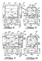
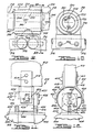
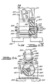
- FIGS 1 through 29 illustrate various exemplary embodiments of a sign stand assembly according to the present invention.
- the present invention is not limited to the sign-supporting embodiments shown for purposes of illustration in the drawings, and that the present invention also finds applicability in devices other than sign stand assemblies.
- a sign stand assembly 10 for supporting a sign 12 in a generally upright orientation relative to a base 14 having one or more legs 16 for engaging the ground or other underlying surface.
- the sign stand assembly 10 also includes one or more sign-supporting members 18 adapted for supporting attachment to the sign 12, and a resilient biasing apparatus 20 for permitting the sign 12 to pivotally deflect relative to the base 14 from its generally upright orientation, as indicated by the arrows 22 shown in Figures 1 and 3.
- the base 14 includes a base bracket 24, to which the legs 16 are preferably attached by fasteners or pins 26.
- the base bracket 24 can be any of a number of various types of structures known to those skilled in the art and is interconnected with the sign-supporting members 18 by the resilient biasing apparatus 20 as discussed in more detail below. It should be noted that one skilled in the art will readily recognize that the base assemblies of the various embodiments discussed herein can alternately include apparatus for attachment to a wall, a column or post, or other structures.
- the sign-supporting member or members 18 are adapted to be secured to the sign 12 by any of a number of suitable attachment mechanisms known to those skilled in the art, such as by way of a pair of attachment brackets 28, shown for purposes of illustration in Figures 1 through 4.
- the sign-supporting members 18 are each generally U-shaped in lateral cross-section and include a pair of downwardly-depending legs 44 and at attachment plate 45, as shown in Figures 2 and 3.
- the resilient biasing apparatus 20 includes an elastomeric member 30, which is preferably of a hollow cylindrical configuration, with its inner peripheral surface fixedly secured or bonded to an inner sleeve or rod 32, and with its outer peripheral surface fixedly secured or bonded to an outer sleeve 34.
- the inner sleeve 32 is shown for purposes of illustration as a generally hollow cylindrical configuration, but can alternately be a solid member having any suitable cross-sectional shape, depending upon the cross-sectional shape of the inner peripheral surface of the elastomeric member 30.
- the elastomeric member 30 and the other elastomeric members described below can be of a vulcanized rubber or other elastomeric polymer composition having suitable durometer hardnesses, spring rates, and other properties, all of which ar now determinable by one skilled in the art in a given application.
- the inner sleeve 32 is preferably secured to the attachment plates 45 of the sign-supporting members 18 by one or more fasteners 38 threadably engaging bosses 35, for example.
- the outer sleeve 34 is secured to the base bracket 24 in any of a number of ways known to those skilled in the art, such as by way of one or more fasteners 36.
- the elastomeric member 30 is preferably compressively preloaded in a generally radially inward direction relative to the torsion axis 40, as well as axially along the torsion axis 40 and in other directions. Such preloading of the elastomeric member 30 is preferably accomplished after it is bonded to the inner and outer sleeves 32 and 34, during mounting of the resilient biasing apparatus 20.
- the outer sleeve 34 includes a split portion 42 of the outer sleeve 34, which extends along the axial length of the outer sleeve 34 and allows the outer sleeve 34 to be deflected or tightened in a circumferential direction (through an arc of approximately one to three degrees) to the position shown in Figure 4, when the outer sleeve 34 is secured to the base bracket 24 by way of the fasteners 36. This is accomplished by first securing one side of the outer sleeve 34 to the base 14 and then rotating the other side of the outer sleeve 34 to the position shown in solid lines in Figure 4 in order to compress the elastomeric member 30 between the inner sleeve 32 and the tightened outer sleeve 34.
- the torsional deflection of the elastomeric 30 is preferably limited by way of a stop member 46, which can be fixed to the outer sleeve 40.
- the stop member 46 protrudes axially from the outer sleeve 34 and is disposed so as to interferingly engage either one of the legs 44 or the attachment plate 45 of the U-shaped sign-supporting member 18 when the elastomeric member 30 torsionally deflects a predetermined amount corresponding to a preselected maximum deflection of the sign 12 in the direction of the arrows 22.
- a preferred maximum amount of torsional deflection of the elastomeric member 30 corresponds to a rotation of the inner sleeve 32 about the torsion axis 40 of approximately 45 degrees in either of the opposite pivotal directions indicated by the arrows 22, which is crucial to the long life and durability of elastomeric member 30 in order to avoid overstressing the elastomer in this cyclically loaded application.
- This amount of deflection has also been found to result in a change in the vector forces on the sign and stand such that the sign and stand is more stable and less susceptible to tipping over in high winds.
- the above-discussed preferred maximum pivotal deflectability of 55 degrees for the sign 12, which corresponds to a preferred maximum torsional defection of 45 degrees in either direction for the elastomeric member 30, has been determined to provide good readability and reflectiveness of the sign 12, while still avoiding the tendency of the sign and sign stand to tip over in high winds, such as in winds up to approximately 100 miles per hour.
- Such a determination was made using a prototype sign and sign stand having legs engaging the ground or other underlying surface at points approximately 24 inches in a lateral direction from a vertical plane passing through the torsion axis 40, with the sign and sign stand assembly having an overall height of 52 inches above the ground.
- the above-mentioned 45 degree deflection of the elastomeric member 30 occurred in response to a force of approximately 38 to 40 pounds directed along an effective vector approximately 36 inches above the ground or other supporting surface.
- the above-mentioned maximum pivotal deflections can be advantageously used in any of the embodiments of the present invention shown and discussed herein.
- Figures 5 and 6 illustrate another embodiment of the present invention, which is generally similar to that shown in Figures 1 through 4, except for the provision of an alternate stop member, which can be employed in lieu of the stop member 46 in virtually any of the embodiments discussed herein.
- most of the components of a sign stand assembly 110 are identical or correspondingly similar to the various components of the sign stand assembly 10 shown in Figures 1 through 4.
- Such identical or correspondingly similar components of the sign stand assembly 110 are thus indicated by reference numerals corresponding to those of the sign stand assembly 10 in Figures 1 through 4, but having a one-hundred "prefix".
- a stop member 146 is substituted for the stop member 46 of sign stand assembly 10 and includes a mounting plate 148 and a triangular portion 150.
- the mounting plates 148 are adapted to be secured to the base bracket 124, with the triangular portions 150 protruding in an offset relationship thereform so as to be disposed for interfering engagement with either the legs 144 or the attachment plates 145 of the sign-supporting members 118 upon torsional deflection of the elastomeric member 130 to the above-discussed predetermined maximum pivotal or rotational positions relative to the torsion axis 140.
- the function of sign stand assembly 110 is substantially the same as that of the sign stand assembly 10 in Figures 1 through 4.
- FIGs 7 and 8 still another alternate embodiment of the present invention is illustrated, wherein a sign stand assembly 210 is generally similar to the sign stand assemblies 10 and 110, shown in Figures 1 through 4 and in Figures 5 and 6, respectively.
- corresponding or similar elements are identified by corresponding reference numerals having a two-hundred "prefix".
- the sign stand assembly 210 includes a hex-shaped sleeve or rod member 238, which extends axially through, and is interlocked for rotation with, an inner sleeve member 232.
- the inner sleeve member 232 has a corresponding hex-shaped opening 249 extending axially therethrough for receiving, and rotationally interlocking with, the hex-shaped member 238.
- the hex-shaped member 238 is preferably fixably secured at one end to at least one of the attachment plates 245 of the sign-supporting members 218, such as by welding as indicated for purposes of illustration at reference numeral 247 in Figure 7, with the opposite end either extending through a hex-shaped opening 251 in the other attachment plate 245 or secured thereto.
- stop member 246 shown in Figures 7 and 8 corresponds to the stop member 146 shown in Figures 5 and 6, the stop member 46 of the sign stand assembly 10 shown in Figures 1 through 4 may alternately be used in conjunction with the sign stand assembly 210 shown in Figures 7 and 8 or with other embodiments of the present invention.
- the hex-shaped cross-section of the member 238 and the openings 249 and 251 can alternately be configured with other polygonal shapes that provide complementary interfering rotational restraint with one another.
- Figures 9 and 10 illustrate another alternate embodiment of the present invention, wherein a sign and stand assembly 310 is generally similar to the sign and stand assemblies of the embodiments illustrated in the previous Figures.
- a sign and stand assembly 310 is generally similar to the sign and stand assemblies of the embodiments illustrated in the previous Figures.
- the identical or correspondingly similar components of the sign and stand assembly 310 are indicated by reference numerals corresponding to those discussed above, except that a three-hundred "prefix" is used.
- a pair of elastomeric members 330 and 331 are provided in the resilient biasing apparatus 320, with the outer elastomeric member 330 being fixedly secured or bonded to the inner periphery of an outer sleeve member 334 and generally surrounding an intermediate sleeve member 333, and inner elastomeric member 331, and an inner sleeve member 332.
- the inner elastomeric member 331 is fixedly secured or bonded to both the inner sleeve member 332 and the intermediate sleeve member 333, which is in turn fixedly secured or bonded to the outer sleeve member 334.
- the outer elastomeric member 330 is composed of an elastomeric material that has a softer durometer hardness, and thus a lower torsional spring rate, than that of the inner elastomeric member 331.
- the inner and outer elastomeric members 331 and 330 respectively, essentially act "in series" with one another in that the inner elastomeric member 331 with the higher torsional spring rate undergoes little or no torsional deflection under low or moderate wind conditions.
- both of the elastomeric members 330 and 331 deflect in order to substantially prevent the sign and sign stand assembly from tipping over.
- the sign does not deflect as much in lower wind conditions, and the durability of the resilient biasing apparatus 320 is enhanced, all without substantially affecting the "wind-proof" performance of the sign stand assembly.
- the sign stand assembly 310 can preferably include either the stop member 46 shown in Figures 1 through 4, or the stop member 146 shown in Figures 5 and 6, both of which are discussed above.
- the softer (lower torsional spring rate) elastomeric member 330 is disposed radially outward from the harder (higher torsional spring rate) elastomeric member 331 in Figures 9 and 10, one skilled in the art will readily recognize that this radial orientation can alternately be reversed, with the inner elastomeric member being softer and having a lower spring rate than the outer elastomeric member.
- FIG. 11 and 12 another alternate sign stand assembly 410 is generally similar to that shown in Figures 1 through 8, and thus corresponding elements of the sign stand assembly 410 are identified by reference numerals with four-hundred "prefixes".
- the sign 412 in Figures 11 and 12 is interconnected with the outer sleeve member 434, and the base 414 is interconnected with the inner sleeve member 432.
- the sign-supporting member or members 418 can be secured directly to the sign 412, as shown in Figures 11 and 12, and include laterally spaced leg portions 423 secured by any suitable means to the outer sleeve member 434, such as by fasteners 421, for example.
- the base 414 includes any of a number of suitable leg-attaching members 424, preferably that allow the legs 418 to be folded up, and that can be secured to the inner sleeve member 432 by way of an attachment plate 429, attachment brackets 427, and fasteners 438, for example.
- the resilient biasing apparatus 420 functions in a manner generally similar to that described above in connection with the embodiments shown in Figures 1 through 8, with the arrangement of the sign stand assembly 410 perhaps being more suitable for some types of sign configurations, or for interconnecting a sign post or other vertical sign component with the resilient biasing apparatus 420. It should also be noted that the resilient biasing apparatus 420, like that of the other embodiments discussed herein, can alternately include the dual-durometer, double elastomeric member arrangement discussed aboe in connection with Figures 9 and 10.
- FIG. 13 and 14 Still another alternate embodiment of the present invention is illustrated in Figures 13 and 14, wherein a sign stand assembly 510 is generally similar to the sign stand assembly 410 of Figures 11 and 12, except that the base 514 is interconnected with the resilient biasing apparatus 520 by way of a hex-shaped sleeve or rod member 538, generally similar to the hex-shaped member 238 shown in Figures 7 and 8.
- a hex-shaped sleeve or rod member 538 generally similar to the hex-shaped member 238 shown in Figures 7 and 8.
- set screws 552 or other suitable fasteners are threadably received in threaded openings 53 in the attachment brackets 527.
- the hex-shaped member 538 is rotationally restrained by, and received in, a hex-shaped opening 549 in the inner sleeve 532.
- the hex-shaped member 238, and the hex-shaped openings 249 and 251 can alternately be configured with other complementary polygonal shapes for interfering rotational restraint with respect to one another.
- Figures 15A through 17 illustrate still another embodiment of the present invention, in which a resilient biasing apparatus includes a pair of elastomeric members acting essentially “in parallel” with one another and torsionally preloaded in opposite torsional, circumferential directions with respect to one another.
- a resilient biasing apparatus includes a pair of elastomeric members acting essentially “in parallel” with one another and torsionally preloaded in opposite torsional, circumferential directions with respect to one another.
- elements shown in Figures 15A through 17 that are similar or that correspond to those of other embodiments are indicated by corresponding reference numerals having six-hundred "prefixes”.
- Figures 15A through 15C illustrate the major sequential steps in making a portion of the resilient biasing apparatus 620 shown in Figures 16A through 17 in connection with an alternate sign stand assembly 610.
- Figure 15A an inner sleeve member 632, with mounting bosses 635 thereon, is fixedly secured or bonded to the inner surface of a generally cylindrical elastomeric member 630, which in turn has its outer peripheral surface fixedly secured or bonded to an outer sleeve member 634.
- This composite assembly is essentially similar to the inner sleeve member 32, the elastomeric member 30, and the outer sleeve member 34 shown in Figures 1 through 4, with the exception that the outer sleeve member 634 is provided with a pair axially-spaced tabs 660 on one radial side, as shown in Figure 15A, and a pair of similar axially-spaced tabs 661 on its outer periphery on the opposite radial side of the outer sleeve member 634.
- the tabs 661 are not visible in Figures 15A and 15B, but their funcltion will become apparent from the discussion below in connection with Figure 15C.
- the subassembly of Figure 15A is cut or otherwise separated or severed along an axially intermediate, radially-extending plane that is radially perpendicular to the axial centerline or torsional axis 640 of the composite assembly.
- This operation forms two separate composite subassemblies, one having an outer sleeve member 634A, an elastomeric member 630a, and an inner sleeve member 632a, with the other composite subassembly having an outer sleeve 634b, an elastomeric member 630b, and an inner sleeve member 632b.
- bosses 635a and 635b in Figure 15B are still circumferentially oriented at the same angle 670 (preferably approximately 10 degrees) with respect to a vertical plane 641 extending through the centerline or torsional axis 640 as they were in Figure 15A before the composite assembly was severed.
- Figure 16A the severed half-subassemblies shown in Figures 15A through 15C have been repositioned end-to-end (as shown in Figure 15C) and mounted onto the base 614 in a manner similar to that discussed above in connected with Figures 1 through 4.
- bosses 635a on the inner sleeve 632a are circumferentially misaligned with respect to the bosses 636b on the inner sleeve 632b, with each of the pairs of bosses 635a and 635b, respectively, being circumferentially offset relative to the vertical plane 641 passing through the centerline or torsional axis 640 in opposite circumferential directions at the previously-mentioned angle 670.
- Figures 16A through 17 best show the arrangement by which the outer sleeve 634a and 634b are rotationally restrained with respect to the mounting clamp 664.
- the radially-protruding tabs 660a and 660b and the opposite tabs 661a and 661b are interlockingly received within slots 666 on opposite sides of the mounting clamp 664.
- the elastomeric members 630a and 630b can be compressively preloaded, as discussed above, in connection with Figures 1 through 4, due to the axially-extending slits 642a and 642b.
- stop member arrangements similar to those shown in Figures 1 through 4 or Figures 5 and 6 are preferably included in the sign stand assembly 610 for purposes of limiting the maximum torsional deflection of the elastomeric member 630a and 630b to correspond with preselected maximum sign deflection of the sign 612.
- Figures 18 and 19 illustrate a preferred form of the present invention, which is similar in many respects to the embodiments of the invention discussed above, and therefore similar or corresponding elements are identified with reference numerals having seven-hundred "prefixes".
- the sign stand assembly 710 shown in Figures 18 and 19 includes a single, one-piece sign-supporting member 718 having a preferred, generally U-shaped cross-section with downwardly-depending legs 744.
- the one-piece sign-supporting member 718 is fixedly secured to a modified form of an outer sleeve member 734, such as by the fasteners 736.
- the outer sleeve member 734 is fixedly secured or bonded to the elastomeric member 730, which is in turn fixedly secured or bonded to the inner sleeve member 732.
- the inner sleeve member 732 is fixedly secured to the base brackets 724 of the base assembly 714.
- the base brackets 724 are configured such that their sides 725 interferingly engage the legs 744 of the sign-supporting member 718 upon torsional deflection of the elastomeric member 730 in order to limit such torsional deflection to the predetermined amounts discussed above.
- stop members similar to the stop members 46 or 146 can be used for this purpose.
- Figures 18 and 19 are especially preferred in suitable applications because of the simplicity and economy of manufacture and assembly resulting from the one-piece design of the sign-supporting member 718.
- One skilled in the art will readily recognize that the embodiment shown in Figures 18 and 19 can alternately be easily modified in order to reverse the arrangement shown such that the one-piece sign-supporting member 718 is interconnected with the inner sleeve member 732 (such as by suitable attachment plates between the legs 744), with the base 714 being interconnected with the outer sleeve member 734 similar to the arrangements shown in the other drawing figures.
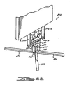
- FIG. 20 a poster display device or means 810 having an upstanding frame structure with a suitable downwardly extending support or support bar 811 which may be rectangular or tubular.
- Such means 810 is a frame structure, however, in the example described as shown as a display device that is adapted to have mounted thereon an advertising sign, poster, or the like.
- Such poster display device is mounted on a base which has a U-shaped bracket 813 having a pair of vertically disposed plates 814 and a bottom plate 815 interconnecting such vertically disposed plates 814.
- Such plates may be a single U-shaped member.
- a plurality of horizontally extending legs 816 are suitably connected to the bottom plate 815 in a manner will known in the art to provide ground engaging means.
- a torsion spring 820 shown in Figures 21 and 22 has a cylindrical shaft member or sleeve 821 with a keyway 822 extending therethrough along its inner bore 823.
- Mounted within bore 823 is an elongated shaft 825 having a keyway therein for receiving a key 26 ( Figure 22) to secure the shaft 825 and the torsion spring 820 together.
- the respective ends of shaft 825 are secured to the vertically disposed plates 814 as by independent keys or other suitable means.
- a generally cylindrical housing member or shell 830 has a pair of outwardly extending legs or leg members 831 and 832 for attaching the torsion spring to the poster display device in a manner to be described.
- the cylindrical housing member 830 is a circumferential shell with a gap 834 formed along its upper circumference between the respective leg members 831 and 832.
- the respective leg members each have a pair of aligned bolt holes.
- a rubber sleeve or annulus of elastomeric material 835, the spring element in the torsion spring, is molded and vulcanized in the space between the shaft member or sleeve 821 and the cylindrical housing member 830, preferably with the use of a suitable rubber-to-metal adhesive and under compression. During the molding process, the rubber fills the entire space between the sleeve 821 and the housing member or shell 830 and is bonded firmly thereto.
- the depending support bar 811 of the poster display device is slid down between leg members 831 and 832 such that the aligned bolt holes in such leg members 831 and 832 are also aligned with bores 836 and 838 in the support bar 811 to facilitate the reception of bolts 839 and 840 to interconnect the torsion spring to the poster display device 810.
- Such housing 830 in its split form as part of the torsion spring itself also functions as a clamp for attachment to other fixtures to facilitate its action as part of the torsion spring.
- Such split outer shell or housing helps to relieve shrinkage stress of the rubber spring sleeve 835 and permits controlled compression of the rubber for greater fatigue life.
- the poster display device 810 In the operation of the poster display device 810, such device 810 will be biased by the torsion spring into an upright position.
- the depending bar 811 of the poster device is clamped by the leg members 831 and 832 of the torsion spring 820 and as an external force is exerted on the poster display device 810, the display device will deflect as shown in phantom lines in Figure 21 to exert a torsion in the rubber of sleeve 835 whose radial innermost surface is held against rotation by the sleeve 821 and its keyed connection to shaft 825.
- the torsion spring will return the poster display device 810 to its normal vertical position.
- Torsion spring 842 has a cylindrical housing or outer shell 843 with a pair of outwardly extending leg members 844 and 845.
- leg members 844 and 845 are much shorter in length than the initial described embodiment of leg members 831 and 832.
- Such leg members 844 and 845 are recessed as at 846 and 847 to receive a pair of connecting links 848 and 849 of an attaching bracket 850.
- Bracket 850 has a pair of vertically disposed side plates 851 and 852 interconnected by a horizontally extending portion 853. Bracket 850 is slid into position when leg members 844 and 845 of shell 843 are moved toward each other permitting the sliding of such connecting links 848 and 849 into the recessed portions 846 and 847 of leg members 844 and 845.
- the respective plates 851 and 852 have pairs of vertically spaced bores for alignment with bores in the support bar 811 and receive bolts 854 and 855 to secure the poster display device 810 and its support bar 811 to the torsion spring 842.
- the shell 843 of the torsion spring 842 has its inner surface bonded to an elastomeric or rubber sleeve 857 similar to rubber sleeve 835, which sleeve 857 in turn has its inner circumferentially extending surface bonded to an inner metallic sleeve 858.
- Inner sleeve 858 has an outer circular surface and an inner non-linear perimeter that defines a polygonal aperture 860.
- a shaft 862 that is hexagonal in cross-section is frictionally received by aperture 860 and hexagonal apertures 863 and 864 in side plates 865 and 866 of a U-shaped bracket 867. Shaft 862 is thus connected to the side plates 865 and 866.
- Such shaft 862 may be keyed to the side plates 865 and 866 or connected thereto in other manners to prevent axial movement of shaft 862.
- Bracket 867 has a plurality of ground engaging leg members 868 suitably connected thereto.
- the manner of attachment to the support bar 811 is similar to the first described embodiment.
- the rubber component such as sleeve 857 of the torsion spring being in compression, the fatigue life of such rubber sleeve component will be increased materially.
- FIG. 25 A further modified embodiment of the invention is shown in Figure 25 wherein a poster display device or means 870 is suitably connected to a pair of depending brackets 871 and 872 forming a support frame.
- brackets 871 and 872 have a pair of aligned polygonal apertures that receive a shaft 875 that is polygonal in cross-section.
- Shaft 875 if frictionally received by the inner polygonal bore of sleeve 876 of a torsion spring 878.
- the cylindrical outer surface of sleeve 876 is bonded to a rubber sleeve or annulus of elastomeric material 879, the spring element in the torsion spring 878.
- rubber sleeve 879 is bonded to the inner cylindrical surface of a housing member or shell 880 which has a gap formed along its lower circumference as shown in Figure 25, similar to the above-described embodiments.
- Such rubber sleeve 879 is molded and vulcanized in the space between the sleeve 876 and the cylindrical housing member or shell 880 preferably with the use of a suitable rubber-to-metal adhesive and under compression. During such molding process, the rubber fills the entire space between the sleeve 876 and the shell 880 and if firmly bonded thereto.
- the outer shell 880 has a pair of outwardly extending legs or leg members 881 and 882 for attaching the torsion spring to an upwardly extending bracket 885 which has a plurality of ground engaging supports 886 suitably connected thereto.
- Bracket 885 has a pair of vertically aligned bores which are adapted to register with bores in leg members 881 and 882 to receive bolts 883 and 884 for connecting these members together while operative to exert a compressive force on the rubber sleeve 879 to thereby materially increase the fatigue life of the rubber component.
- FIG. 26 through 29 A further modification of the above described embodiments is shown in Figures 26 through 29 wherein a poster display device 890 is suitably connected to a depending bracket 891 forming a support frame.
- bracket 891 is connected to a pair of spaced outwardly extending leg members 892 and 893 of an outer shell 895.
- the respective leg members 892 and 893 have suitable apertures aligned with apertures 896 and 897 in bracket 891 to facilitate the reception of bolts 898 for interconnecting such leg members to the bracket 891.
- An annular elastomeric member 900 has its outer surface suitably bonded to the inner peripheral surface of outer shell 895 similar to the prior described embodiments.
- the inner circumferentially extending surface of the elastomeric annular member 900 is suitably bonded to the outer surface of a tubular metal sleeve 901, which sleeve 901 has a flattened extendion 902.
- Such above described torsion spring is mounted in a base which has a U-shaped bracket 910 having a pair of vertically disposed plates 911 and a bottom plate 912 interconnecting such vertically disposed plates 911.
- Such plates may be a single U-shaped member.
- a plurality of horizontally extending legs 914 are suitably connected to the bottom plate 912 as by welding.
- the one vertical plate 911 of bracket 910 has a slot 915 to receive the flattened extension 902 of sleeve 901.
- the other vertical plate 911 of bracket 910 has an aperture 918 to receive the cylindrical portion 919 of plug 920.
- plug 920 is frictionally received by the end bore 921 of tubular sleeve 901 that is opposite the flattened extension 902 of such sleeve 901 to retain the torsion spring on the U-shaped bracket 910 of the base.
- the end portion of the bore 921 may be threaded as at 923 to receive a threaded plug 925 which facilitates the interconnection of the torsion spring onto the base.
- Such elastomeric member 900 is molded and vulcanized in the space between the sleeve 901 and the outer shell 895 which has a gap formed along its leg members 892 and 893.
- Such elastomeric sleeve 900 is molded and vulcanized in the space between the sleeve 901 and the outer shell 895 preferably with the use of a suitable rubber-to-metal adhesive and under compression. During such molding process, the elastomeric material fills the entire space between the sleeve 901 and the shell 895 and is firmly bonded thereto.
Landscapes
- Engineering & Computer Science (AREA)
- Architecture (AREA)
- Civil Engineering (AREA)
- Structural Engineering (AREA)
- General Engineering & Computer Science (AREA)
- Child & Adolescent Psychology (AREA)
- Health & Medical Sciences (AREA)
- Mechanical Engineering (AREA)
- Physics & Mathematics (AREA)
- General Physics & Mathematics (AREA)
- Theoretical Computer Science (AREA)
- Road Signs Or Road Markings (AREA)
- Springs (AREA)
- Pressure Welding/Diffusion-Bonding (AREA)
Applications Claiming Priority (2)
| Application Number | Priority Date | Filing Date | Title |
|---|---|---|---|
| US905673 | 1986-09-09 | ||
| US06/905,673 US4714220A (en) | 1986-01-31 | 1986-09-09 | Sign stand assembly |
Related Child Applications (3)
| Application Number | Title | Priority Date | Filing Date |
|---|---|---|---|
| EP91203030.1 Division-Into | 1987-07-27 | ||
| EP93102371.7 Division-Into | 1987-07-27 | ||
| EP19910203030 Division EP0475537A3 (en) | 1986-09-09 | 1987-07-27 | Resilient biasing device |
Publications (2)
| Publication Number | Publication Date |
|---|---|
| EP0263579A2 true EP0263579A2 (fr) | 1988-04-13 |
| EP0263579A3 EP0263579A3 (fr) | 1988-07-13 |
Family
ID=25421250
Family Applications (1)
| Application Number | Title | Priority Date | Filing Date |
|---|---|---|---|
| EP87306614A Withdrawn EP0263579A3 (fr) | 1986-09-09 | 1987-07-27 | Support pour panneau |
Country Status (5)
| Country | Link |
|---|---|
| US (1) | US4714220A (fr) |
| EP (1) | EP0263579A3 (fr) |
| JP (1) | JPS6370279A (fr) |
| AU (3) | AU599136B2 (fr) |
| CA (1) | CA1275805C (fr) |
Cited By (1)
| Publication number | Priority date | Publication date | Assignee | Title |
|---|---|---|---|---|
| FR2664921A1 (fr) * | 1990-07-20 | 1992-01-24 | Seri | Dispositif a barriere pivotante articulee. |
Families Citing this family (15)
| Publication number | Priority date | Publication date | Assignee | Title |
|---|---|---|---|---|
| US5094023A (en) * | 1990-09-13 | 1992-03-10 | Meadowlark Manufacturing, Inc. | Roadway safety sign stand apparatus |
| US5303907A (en) * | 1992-08-31 | 1994-04-19 | The B. F. Goodrich Company | Variable rate elastomeric torsion spring |
| US5382007A (en) * | 1992-08-31 | 1995-01-17 | The B. F. Goodrich Company | Constant force torsion spring apparatus |
| US5456644A (en) * | 1993-10-20 | 1995-10-10 | Roadmaster Corp. | Multiple station exercise machine having relocatable torsion resistance mechanisms |
| US5632710A (en) * | 1993-10-20 | 1997-05-27 | Roadmaster Corporation | Exercise apparatus |
| AU669471B3 (en) * | 1995-02-02 | 1996-06-06 | Barry, Kevin John | Sign Board with pivotting foot member |
| USD379483S (en) * | 1995-03-01 | 1997-05-27 | Roadmaster Corporation | Combination abdominal and back exerciser |
| US6056250A (en) * | 1998-08-12 | 2000-05-02 | Marketing Displays International | Sign stand for flexible traffic control signage |
| EP1085992B1 (fr) | 1999-04-16 | 2003-12-03 | Compagnie Générale des Etablissement Michelin-Michelin & Cie | Element formant articulation de suspension et ressort de torsion, en particulier pour vehicule |
| US6435491B1 (en) | 1999-10-04 | 2002-08-20 | Compagnie Generale Des Etablissements Michelin-Michelin & Cie | Flexible joint for a vehicle suspension device and process for stabilizing the mechanical operating characteristics of a flexible joint for a vehicle suspension device |
| CN101523077A (zh) * | 2005-08-11 | 2009-09-02 | 里奇科有限责任公司 | 弹性轴阻尼器 |
| US20080236010A1 (en) * | 2007-04-02 | 2008-10-02 | Eugene Levin | Torsion spring base for deflectable sign |
| US20100127136A1 (en) * | 2008-01-21 | 2010-05-27 | Brad Markoff | Lug-mount system for free standing display stand arm |
| CN111851348B (zh) * | 2020-07-15 | 2022-01-04 | 重庆东吴交通设施有限公司 | 一种道路交通标识牌安装固定结构 |
| US12060686B2 (en) * | 2020-12-04 | 2024-08-13 | Argo Corp, Inc. | Roadway safety device |
Family Cites Families (28)
| Publication number | Priority date | Publication date | Assignee | Title |
|---|---|---|---|---|
| US1615576A (en) * | 1926-06-07 | 1927-01-25 | Ezra L Estes | Depressible traffic signal |
| US1694756A (en) * | 1926-06-12 | 1928-12-11 | Gen Motors Res Corp | Support for internal-combustion engines with rubber cushions |
| US1662298A (en) * | 1927-05-16 | 1928-03-13 | Samuel J Bialosky | Traffic signal |
| US1958141A (en) * | 1931-09-23 | 1934-05-08 | Goodrich Co B F | Method of making alpha flexible connection |
| US2073450A (en) * | 1933-02-10 | 1937-03-09 | Mechana Kold Corp | Vibration damping mounting for compressors, etc. |
| US2051864A (en) * | 1934-04-17 | 1936-08-25 | Harry A Knox | Suspension for vehicles |
| DE688421C (de) * | 1936-01-01 | 1940-02-20 | Continental Gummi Werke Akt Ge | Abfederung, insbesondere fuer Kraftfahrzeuge, mit mehreren hintereinandergeschalteten Federn verschiedener Staerke |
| CH190296A (de) * | 1937-01-30 | 1937-04-15 | Schreiber Erwin | Einrichtung zur Abfederung von Schwingarmen, insbesondere für Fahrzeuge. |
| GB532393A (en) * | 1939-07-21 | 1941-01-23 | Silentbloc | Improvements in or relating to flexible joints |
| US2409500A (en) * | 1943-02-03 | 1946-10-15 | Goodrich Co B F | Spring |
| US2577761A (en) * | 1948-11-04 | 1951-12-11 | Hickman Ind Inc | Spring suspension for vehicles |
| BE510290A (fr) * | 1948-11-12 | |||
| US3120942A (en) * | 1961-05-23 | 1964-02-11 | Knoll Associates | Chair control |
| US3204953A (en) * | 1962-06-18 | 1965-09-07 | Claude W Ahrens | Rocking animal structure |
| US3204914A (en) * | 1964-04-20 | 1965-09-07 | Seng Co | Chair control |
| US3336021A (en) * | 1965-06-11 | 1967-08-15 | Goodrich Co B F | Rubber torsion spring |
| SE219109C1 (fr) * | 1966-04-20 | 1968-02-20 | ||
| US3646696A (en) * | 1967-09-11 | 1972-03-07 | Robert Sarkisian | Poster display device |
| US3662482A (en) * | 1970-07-30 | 1972-05-16 | Robert Sarkisian | Poster display device |
| JPS5020759B2 (fr) * | 1971-12-29 | 1975-07-17 | ||
| US3770291A (en) * | 1972-03-17 | 1973-11-06 | Goodrich Co B F | Vehicle suspension |
| DE2410627A1 (de) * | 1974-03-06 | 1975-09-11 | Guenter Heidt | Traeger fuer hinweisschilder, insbesondere verkehrsschilder |
| US4033536A (en) * | 1976-04-08 | 1977-07-05 | Robert Sarkisian | Mounting bracket coil spring |
| JPS5446466A (en) * | 1977-09-19 | 1979-04-12 | Nec Home Electronics Ltd | Manufacture of semiconductor device |
| FR2484679B1 (fr) * | 1980-06-17 | 1985-09-27 | Paillet Aime | Support de panneau de signalisation routiere |
| US4365435A (en) * | 1980-11-03 | 1982-12-28 | Chicago Display Company | Portable sign |
| EP0139858A3 (fr) * | 1983-08-23 | 1986-03-26 | marketing-displays Produktionsgesellschaft für Werbe- und Verkaufsförderungssysteme mbH | Support pour des affiches |
| DE3345797A1 (de) * | 1983-12-17 | 1985-06-27 | Gubela Straßenausrüstungs-GmbH, 5000 Köln | Verkehrsbake |
-
1986
- 1986-09-09 US US06/905,673 patent/US4714220A/en not_active Expired - Lifetime
-
1987
- 1987-07-27 EP EP87306614A patent/EP0263579A3/fr not_active Withdrawn
- 1987-07-28 CA CA000543151A patent/CA1275805C/fr not_active Expired - Lifetime
- 1987-08-17 JP JP62203971A patent/JPS6370279A/ja active Pending
- 1987-09-09 AU AU78197/87A patent/AU599136B2/en not_active Ceased
-
1990
- 1990-05-29 AU AU56042/90A patent/AU626162B2/en not_active Ceased
- 1990-05-29 AU AU56041/90A patent/AU615386B2/en not_active Ceased
Cited By (1)
| Publication number | Priority date | Publication date | Assignee | Title |
|---|---|---|---|---|
| FR2664921A1 (fr) * | 1990-07-20 | 1992-01-24 | Seri | Dispositif a barriere pivotante articulee. |
Also Published As
| Publication number | Publication date |
|---|---|
| US4714220A (en) | 1987-12-22 |
| AU626162B2 (en) | 1992-07-23 |
| AU5604190A (en) | 1990-09-20 |
| AU615386B2 (en) | 1991-09-26 |
| EP0263579A3 (fr) | 1988-07-13 |
| JPS6370279A (ja) | 1988-03-30 |
| AU7819787A (en) | 1988-03-17 |
| AU5604290A (en) | 1990-09-13 |
| CA1275805C (fr) | 1990-11-06 |
| AU599136B2 (en) | 1990-07-12 |
Similar Documents
| Publication | Publication Date | Title |
|---|---|---|
| US4714220A (en) | Sign stand assembly | |
| EP1009940B1 (fr) | Bague de compression elastique en forme de sablier | |
| US5149066A (en) | Isolator with improved symmetrical response to shock and vibration forces | |
| US6792689B2 (en) | Remote center compliance device | |
| US4033536A (en) | Mounting bracket coil spring | |
| US3851616A (en) | Portable traffic marker | |
| DE102016014280B4 (de) | Anschweißbare FBG-Dehnungssensoranordnung | |
| US5444429A (en) | Electrical assembly with surge arrester and insulator | |
| US3724833A (en) | Reversible energy absorbing bumper system | |
| US7665371B2 (en) | Device and method for measuring forces and moments | |
| EP1480844B1 (fr) | Palier de support conique | |
| AU751464B2 (en) | Shock absorbing support | |
| US4754991A (en) | Method and buffer apparatus for preventing corrosion in dynamic load bearing assembly | |
| EP0549565A2 (fr) | Dispositif de fixation élastique | |
| CN214502629U (zh) | 一种稳定型的自复位柱式称重传感器 | |
| JP4091116B2 (ja) | サージアレスター | |
| EP3604003A1 (fr) | Butée composite à encliqueter sur piston composite | |
| DE102014013042B4 (de) | Kraftmessvorrichtung | |
| NL8702794A (nl) | Voetsamenstel voor reclameborden of dergelijke. | |
| JP6558691B2 (ja) | ロードセル | |
| CN221079731U (zh) | 复合绝缘子 | |
| CN219586547U (zh) | 一种抗震支座 | |
| CN113005887A (zh) | 一种插接式摇摆桥墩 | |
| DE202006020922U1 (de) | Vorrichtung zur Befestigung einer Achsmesskopfanordnung an einem Fahrzeug | |
| CN110294144B (zh) | 一种作动筒支架及具有其的作动加载装置 |
Legal Events
| Date | Code | Title | Description |
|---|---|---|---|
| PUAI | Public reference made under article 153(3) epc to a published international application that has entered the european phase |
Free format text: ORIGINAL CODE: 0009012 |
|
| AK | Designated contracting states |
Kind code of ref document: A2 Designated state(s): DE ES FR GB SE |
|
| PUAL | Search report despatched |
Free format text: ORIGINAL CODE: 0009013 |
|
| 17P | Request for examination filed |
Effective date: 19880428 |
|
| AK | Designated contracting states |
Kind code of ref document: A3 Designated state(s): DE ES FR GB SE |
|
| 17Q | First examination report despatched |
Effective date: 19910222 |
|
| STAA | Information on the status of an ep patent application or granted ep patent |
Free format text: STATUS: THE APPLICATION IS DEEMED TO BE WITHDRAWN |
|
| 18D | Application deemed to be withdrawn |
Effective date: 19930225 |
|
| RIN1 | Information on inventor provided before grant (corrected) |
Inventor name: COPE, DENNIS RAY Inventor name: HILLSTROM, DAVID UNO |