EP0263701A2 - Armature de borne électrique - Google Patents
Armature de borne électrique Download PDFInfo
- Publication number
- EP0263701A2 EP0263701A2 EP87308901A EP87308901A EP0263701A2 EP 0263701 A2 EP0263701 A2 EP 0263701A2 EP 87308901 A EP87308901 A EP 87308901A EP 87308901 A EP87308901 A EP 87308901A EP 0263701 A2 EP0263701 A2 EP 0263701A2
- Authority
- EP
- European Patent Office
- Prior art keywords
- wire
- terminal
- cap
- contact support
- fitting
- Prior art date
- Legal status (The legal status is an assumption and is not a legal conclusion. Google has not performed a legal analysis and makes no representation as to the accuracy of the status listed.)
- Withdrawn
Links
- 239000000565 sealant Substances 0.000 claims abstract description 13
- 238000009413 insulation Methods 0.000 claims abstract description 8
- 239000004020 conductor Substances 0.000 claims description 4
- 238000000034 method Methods 0.000 claims description 3
- 230000000717 retained effect Effects 0.000 claims 2
- 239000008393 encapsulating agent Substances 0.000 claims 1
- 239000002184 metal Substances 0.000 abstract description 2
- 229910052751 metal Inorganic materials 0.000 abstract description 2
- 238000005538 encapsulation Methods 0.000 description 3
- 238000012986 modification Methods 0.000 description 2
- 230000004048 modification Effects 0.000 description 2
- 238000000465 moulding Methods 0.000 description 2
- RYGMFSIKBFXOCR-UHFFFAOYSA-N Copper Chemical compound [Cu] RYGMFSIKBFXOCR-UHFFFAOYSA-N 0.000 description 1
- 239000004593 Epoxy Substances 0.000 description 1
- 230000015572 biosynthetic process Effects 0.000 description 1
- 229910052802 copper Inorganic materials 0.000 description 1
- 239000010949 copper Substances 0.000 description 1
- 239000004519 grease Substances 0.000 description 1
- 238000001746 injection moulding Methods 0.000 description 1
- 235000015110 jellies Nutrition 0.000 description 1
- 239000008274 jelly Substances 0.000 description 1
- 230000014759 maintenance of location Effects 0.000 description 1
- 229920000647 polyepoxide Polymers 0.000 description 1
- 229920005749 polyurethane resin Polymers 0.000 description 1
- 229920005989 resin Polymers 0.000 description 1
- 239000011347 resin Substances 0.000 description 1
- 238000007789 sealing Methods 0.000 description 1
Images


Classifications
-
- H—ELECTRICITY
- H01—ELECTRIC ELEMENTS
- H01R—ELECTRICALLY-CONDUCTIVE CONNECTIONS; STRUCTURAL ASSOCIATIONS OF A PLURALITY OF MUTUALLY-INSULATED ELECTRICAL CONNECTING ELEMENTS; COUPLING DEVICES; CURRENT COLLECTORS
- H01R43/00—Apparatus or processes specially adapted for manufacturing, assembling, maintaining, or repairing of line connectors or current collectors or for joining electric conductors
- H01R43/20—Apparatus or processes specially adapted for manufacturing, assembling, maintaining, or repairing of line connectors or current collectors or for joining electric conductors for assembling or disassembling contact members with insulating base, case or sleeve
-
- H—ELECTRICITY
- H01—ELECTRIC ELEMENTS
- H01R—ELECTRICALLY-CONDUCTIVE CONNECTIONS; STRUCTURAL ASSOCIATIONS OF A PLURALITY OF MUTUALLY-INSULATED ELECTRICAL CONNECTING ELEMENTS; COUPLING DEVICES; CURRENT COLLECTORS
- H01R4/00—Electrically-conductive connections between two or more conductive members in direct contact, i.e. touching one another; Means for effecting or maintaining such contact; Electrically-conductive connections having two or more spaced connecting locations for conductors and using contact members penetrating insulation
- H01R4/24—Connections using contact members penetrating or cutting insulation or cable strands
- H01R4/2416—Connections using contact members penetrating or cutting insulation or cable strands the contact members having insulation-cutting edges, e.g. of tuning fork type
- H01R4/242—Connections using contact members penetrating or cutting insulation or cable strands the contact members having insulation-cutting edges, e.g. of tuning fork type the contact members being plates having a single slot
- H01R4/2425—Flat plates, e.g. multi-layered flat plates
Definitions
- the present invention relates to an electrical terminal fitting for connecting an insulating wire to an electrical terminal which has a cutting edge
- the fitting comprising a push contact support having two spaced engagement parts which will pass on either side of the terminal cutting edge, the engagement parts being arranged to engage the insulated wire while pushing the contact support home and being positioned so that as the contact support is pushed home, the engagement parts push the wire against the terminal cutting edge so that the edge cuts through the insulation of the wire and engages the wire conductor, guide means for guiding the motion of the contact support as it is pushed over the terminal so that the wire is correctly positioned in relation to the terminal cutting edge, and retaining means for retaining the contact support in position with the cutting edge engaging the wire conductor.
- connection can be made without using any tools, and also so that the connection can be made without needing great skill and so can be made in awkward locations or by less skilled workers; it is also desirable that the connection should be made quickly. All these desiderata must however be consistent with the formation of a good electrical connection which, under normal conditions of use, will not become disconnected.
- GB-A-2 117 190, GB 1 535 159 and EP-A1 0 079 722 all show a terminal having a reentrant or slit and opposed cutting edge between which the wire is pushed. All these are relatively complicated and are not particularly suitable for holding a sealant.
- the present invention provides an electrical terminal fittings as set forth in Claim 1 and a method as set forth in Claim 11.
- the remaining Claims set forth optional features of the invention.
- the cap preferably is of rectangular or square section.
- the cap may be filled to a suitable level with contact sealant to seal the connection, making encapsulation unnecessary and also enabling the connection to be dismantled; a particular advantage of this is that the amount of sealant is low so that expensive proprietary sealants can be used without great overall cost.
- the sealant can be inserted after pushing on the cap, for instance by injecting through a hole in the end of the cap, or normal encapsulation can be carried out, for instance again using a hole in the end of the cap.
- the invention provides a fitting which is capable of cutting the insulation and terminating wire of thin section.
- the wire is guided onto the cutting edge of the terminal.
- the guide means may simply be a sliding fit between the cap and the terminal or a part associated with it, or even an arrangement of the terminal itself which engages the wire and ensures that the wire passes correctly down the cutting edge.
- the guide means is as set forth in Claim 10.
- the retaining means may be a simple friction fit to ensure that the cap does not fall off.
- the retaining means is a snap fitting - the user by finger pressure senses when the cap is fully home.
- At least one of the retaining parts is a hole, through which the wire can be passed before pushing on the cap, and the skill required for connecting the wire to the terminal is very low, enabling connections to be made in awkward locations or by less skilled workers. All that is necessary is to thread the wire through the hole and push the cap home with finger pressure, and in a single operation, the insulation of the wire is penetrated and the contact made. The operation can be carried out without using any tools - this is significant particularly if the item of electrical equipment concerned is itself an electrical connector which does not require tools for making other connections - such a connector is described in GB-A-2 173 653 or EP-A-0 196 925.
- the engaging parts can for instance be registering holes, they are preferably as set forth in Claim 4.
- the wire can be sealed where it enters the cap, the wire can be totally encapsulated.
- the wire does not project through to the other side, and does not leave a bare end which needs to be sealed; the bare end of the wire is within the cap, which in itself affords it some protection; if sealing is required, this can simply be accomplished, for instance using contact sealant or normal encapsulation.
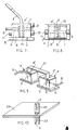
- Figures 1 to 3 show a terminal unit 1 generally as shown in Figure 3 of GB-A-2 173 653 (referred to above), which can be included in a stack of similar units held together with rods, generally as shown in Figure 4 of GB-A-2 173 653.
- the unit 1 is an electrical connector for making connections in telecommunications networks without using any tools. Reference can be made to GB-A-2 173 653 for a general description and details.
- the unit 1 has a terminal 2 in the form of a rectangular-section metal strip of for instance berylium copper.
- the open end of the strip 2 is formed with an open two-edged cutting jaw by means of a reentrant or slit, the sides of which form facing cutting edges 3 (see Figure 4).
- a separate contact support or cap 4 can be pushed rectilinearly onto the terminal 2 by finger pressure - the cap 4 can be very small, the head 5 for instance being a rectangle of 13 ⁇ 8 mm.
- the cap 4 has a rectangular-section or box-section skirt 6 which provides two, spaced wire-engagement parts which will pass on either side of the terminal cutting edge 3, and which are on opposite sides of the skirt 6 One of these parts defines or is formed by a hole 7 through which an insulated wire 8 can be passed before pushing on the cap 4.
- the hole 7 registers with a recess in the form of a slot 7 ⁇ which is open upwards (see Figure 5).
- the slot 7 ⁇ provides a base 7 ⁇ upon which the wire 8 can rest, for retention and thereby forming the other engagement part, and an abutment face 7 ⁇ for engaging the end of the wire 8 and preventing the wire 8 being pushed right through.
- the slot 7 ⁇ can be made by a blade-shaped projection on the core which forms the central recess 4 ⁇ in the cap 4.
- the skirt 6 surrounds the terminal 2. As the cap 4 is pushed on, the cutting edges 3 cut through the insulation of the wire 8 and engage the wire proper.
- the cap 4 has two projections 9,10 on one side (see Figure 2) and one or two projections 11,11 ⁇ on the other side ( Figure 2 shows two while Figure 7 shows one). In each pair, the projections 9,10 or 11,11 ⁇ are on either side of the position to be occupied by the wire 8. These projections 9,10,11,11 ⁇ engage in respective slots 12 (see Figure 1) which are defined between cooperating faces of adjacent terminal units 1.
- the projections 9,10,11,11 ⁇ and slots 12 also provide a snap fitting for retaining the cap 4 in position with the terminal cutting edge 3 engaging the wire 8 proper.
- at least the slot that is entered by the projections 9,10 has two enlarged portions 13 (the other slot will have one or two enlarged portions 13 for accommodating the projections 11,11 ⁇ ). In this way, the cap 4 can be locked in position on the respective terminal unit 1.
- the cap 4 can be pre-filled with a metered amount of contact sealant 14 (indicated in Figure 2), which would normally be a grease.
- a hole 15 (shown dashed in Figures 5, 6 and 8) may be formed in the head 6 of the cap 4 and sealant (e.g. a sealant jelly) injected later.
- sealant e.g. a sealant jelly
- the hole 15 can be used for injecting an encapsulating resin such as an epoxy or polyurethane resin.
- the cap 4 and the bodies of the units 1 can be made by injection moulding.
- Figures 7 and 8 show that the retaining parts can define two registering holes 7. The wire 8 is pushed through both holes 7 before pushing on the cap 4.
- Figure 9 shows that the terminal 21 can be of U-shape with double cutting edges 3 on each end and engaged by two caps 4, to provide a simple wire-in wire-out facility.
- Figure 10 shows that the fitting can be adapted to provide a terminal 22 on both sides of a printed circuit board 23.
Landscapes
- Engineering & Computer Science (AREA)
- Manufacturing & Machinery (AREA)
- Connections By Means Of Piercing Elements, Nuts, Or Screws (AREA)
- Connector Housings Or Holding Contact Members (AREA)
Applications Claiming Priority (4)
| Application Number | Priority Date | Filing Date | Title |
|---|---|---|---|
| GB868624036A GB8624036D0 (en) | 1986-10-07 | 1986-10-07 | Electrical terminal fitting |
| GB8624036 | 1986-10-07 | ||
| GB8706414 | 1987-03-18 | ||
| GB878706414A GB8706414D0 (en) | 1987-03-18 | 1987-03-18 | Electrical terminal fitting |
Publications (2)
| Publication Number | Publication Date |
|---|---|
| EP0263701A2 true EP0263701A2 (fr) | 1988-04-13 |
| EP0263701A3 EP0263701A3 (fr) | 1989-04-26 |
Family
ID=26291393
Family Applications (1)
| Application Number | Title | Priority Date | Filing Date |
|---|---|---|---|
| EP87308901A Withdrawn EP0263701A3 (fr) | 1986-10-07 | 1987-10-07 | Armature de borne électrique |
Country Status (1)
| Country | Link |
|---|---|
| EP (1) | EP0263701A3 (fr) |
Cited By (1)
| Publication number | Priority date | Publication date | Assignee | Title |
|---|---|---|---|---|
| EP0622274A1 (fr) * | 1993-04-28 | 1994-11-02 | Sumitomo Wiring Systems, Ltd. | Connecteur électrique, faisceau électrique et procédé pour fabriquer un tel faisceau |
Family Cites Families (6)
| Publication number | Priority date | Publication date | Assignee | Title |
|---|---|---|---|---|
| US3949467A (en) * | 1974-08-05 | 1976-04-13 | Minnesota Mining And Manufacturing Company | Solderless electrical connector element application method and apparatus |
| US3923362A (en) * | 1974-12-19 | 1975-12-02 | Northern Electric Co | Wire connecting blocks |
| DE3203651A1 (de) * | 1982-02-03 | 1983-08-18 | Maigler, geb. Maigler, Brigitta, 7100 Heilbronn | Steckverbinder und verbinder leiterplatte-kabel mit schneid-klemmkontaktanschluessen zum anschliessen von kabeln mit mehreren, mechanisch voneinander unabhaenigen, einzelleitern |
| CH653813A5 (de) * | 1982-02-10 | 1986-01-15 | Woertz Oskar | Elektrische klemme. |
| GB8508682D0 (en) * | 1985-04-03 | 1985-05-09 | Lucy & Co Ltd W | Electrical connector |
| US4645285A (en) * | 1985-08-26 | 1987-02-24 | Amp Incorporated | Sealed insulation displacement connector |
-
1987
- 1987-10-07 EP EP87308901A patent/EP0263701A3/fr not_active Withdrawn
Cited By (1)
| Publication number | Priority date | Publication date | Assignee | Title |
|---|---|---|---|---|
| EP0622274A1 (fr) * | 1993-04-28 | 1994-11-02 | Sumitomo Wiring Systems, Ltd. | Connecteur électrique, faisceau électrique et procédé pour fabriquer un tel faisceau |
Also Published As
| Publication number | Publication date |
|---|---|
| EP0263701A3 (fr) | 1989-04-26 |
Similar Documents
| Publication | Publication Date | Title |
|---|---|---|
| EP0817313B1 (fr) | Assemblage de connecteur éléctrique à déplacement d'isolant avec dispositif de serrage de câble | |
| EP0220884B1 (fr) | Bloc à bornes avec des connecteurs à déplacement d'isolant | |
| US5073126A (en) | Electrical connector housing having conductor-retention means | |
| US3954320A (en) | Electrical connecting devices for terminating cords | |
| US5364288A (en) | Electrical connecting device | |
| US5009612A (en) | Multi-conductor electrical cable connector | |
| US5478252A (en) | Disconnectable male connector for communications networks | |
| US20020115355A1 (en) | Joint connector | |
| EP0386742A1 (fr) | Connecteur électrique avec contacts de culot de grandeur différente ayant des moyens pour éviter une connexion erronée | |
| US3474394A (en) | Means for making electrical connections | |
| CA2516444A1 (fr) | Systeme et procede de connexion d'un instrument electrochirurgical a un generateur | |
| JPS63308878A (ja) | 接続接点をもつ接続具 | |
| US4354718A (en) | Dual-in-line package carrier and socket assembly | |
| US6283793B1 (en) | Electrical connector system | |
| US6468103B1 (en) | Insulation displacement connector for parallel wire insertion | |
| US4508410A (en) | Electrical termination system and connector member | |
| CN119787013A (zh) | 具有切割片的电连接器外壳及其使用方法 | |
| US4697340A (en) | Method of manufacturing a carrier assembly | |
| US4426121A (en) | Plug for masking switching contacts | |
| US4232927A (en) | Electrical connector | |
| US4027096A (en) | Electrical device housing | |
| EP0263701A2 (fr) | Armature de borne électrique | |
| US4381880A (en) | Multiple electrical connector and block | |
| US5057035A (en) | Telephone extension socket | |
| US4971572A (en) | Electrical connector |
Legal Events
| Date | Code | Title | Description |
|---|---|---|---|
| PUAI | Public reference made under article 153(3) epc to a published international application that has entered the european phase |
Free format text: ORIGINAL CODE: 0009012 |
|
| AK | Designated contracting states |
Kind code of ref document: A2 Designated state(s): AT BE CH DE ES FR GB GR IT LI LU NL SE |
|
| PUAL | Search report despatched |
Free format text: ORIGINAL CODE: 0009013 |
|
| AK | Designated contracting states |
Kind code of ref document: A3 Designated state(s): AT BE CH DE ES FR GB GR IT LI LU NL SE |
|
| 17P | Request for examination filed |
Effective date: 19891220 |
|
| 17Q | First examination report despatched |
Effective date: 19911009 |
|
| STAA | Information on the status of an ep patent application or granted ep patent |
Free format text: STATUS: THE APPLICATION IS DEEMED TO BE WITHDRAWN |
|
| 18D | Application deemed to be withdrawn |
Effective date: 19920220 |
|
| RIN1 | Information on inventor provided before grant (corrected) |
Inventor name: BAKER, COLIN Inventor name: INGLEDEW, DAVID RICHARD |