EP0263717B1 - Balance pour tonneaux - Google Patents
Balance pour tonneaux Download PDFInfo
- Publication number
- EP0263717B1 EP0263717B1 EP87308962A EP87308962A EP0263717B1 EP 0263717 B1 EP0263717 B1 EP 0263717B1 EP 87308962 A EP87308962 A EP 87308962A EP 87308962 A EP87308962 A EP 87308962A EP 0263717 B1 EP0263717 B1 EP 0263717B1
- Authority
- EP
- European Patent Office
- Prior art keywords
- drum
- diaphragm
- capsule
- support
- weighing
- Prior art date
- Legal status (The legal status is an assumption and is not a legal conclusion. Google has not performed a legal analysis and makes no representation as to the accuracy of the status listed.)
- Expired - Lifetime
Links
- 238000005303 weighing Methods 0.000 claims description 22
- 239000002775 capsule Substances 0.000 claims description 20
- 230000000284 resting effect Effects 0.000 claims description 6
- 238000013022 venting Methods 0.000 claims 1
- 238000005452 bending Methods 0.000 description 3
- 229910001220 stainless steel Inorganic materials 0.000 description 2
- 239000010935 stainless steel Substances 0.000 description 2
- HCHKCACWOHOZIP-UHFFFAOYSA-N Zinc Chemical compound [Zn] HCHKCACWOHOZIP-UHFFFAOYSA-N 0.000 description 1
- 239000004020 conductor Substances 0.000 description 1
- 238000010276 construction Methods 0.000 description 1
- 230000005484 gravity Effects 0.000 description 1
- 239000004973 liquid crystal related substance Substances 0.000 description 1
- 238000004519 manufacturing process Methods 0.000 description 1
- 238000000034 method Methods 0.000 description 1
- 238000010079 rubber tapping Methods 0.000 description 1
- 239000011701 zinc Substances 0.000 description 1
- 229910052725 zinc Inorganic materials 0.000 description 1
Images
Classifications
-
- G—PHYSICS
- G01—MEASURING; TESTING
- G01G—WEIGHING
- G01G17/00—Apparatus for or methods of weighing material of special form or property
-
- G—PHYSICS
- G01—MEASURING; TESTING
- G01G—WEIGHING
- G01G19/00—Weighing apparatus or methods adapted for special purposes not provided for in the preceding groups
-
- G—PHYSICS
- G01—MEASURING; TESTING
- G01G—WEIGHING
- G01G3/00—Weighing apparatus characterised by the use of elastically-deformable members, e.g. spring balances
- G01G3/12—Weighing apparatus characterised by the use of elastically-deformable members, e.g. spring balances wherein the weighing element is in the form of a solid body stressed by pressure or tension during weighing
- G01G3/14—Weighing apparatus characterised by the use of elastically-deformable members, e.g. spring balances wherein the weighing element is in the form of a solid body stressed by pressure or tension during weighing measuring variations of electrical resistance
- G01G3/1402—Special supports with preselected places to mount the resistance strain gauges; Mounting of supports
- G01G3/141—Special supports with preselected places to mount the resistance strain gauges; Mounting of supports the supports being disc or ring shaped
Definitions
- This invention relates to weighers for drums and barrels and their contents.
- EP-A-0161708 there is described, as a weighing element for a weighing apparatus, a plate-shaped bending element provided with strain-gauge transducers, one end of the bending element being secured to a frame while the other end is secured to a resilient force-transmitting arm.
- a weigher for drums, barrels and the like comprising a base to stand on the floor, a load support provided on the base at a low level near the floor, a rest member carried on the load support and upon which a point around the bottom edge of a drum or the like to be weighed is rested, the diametrically opposite point of the bottom edge of the drum resting on the floor, the weight load being sensed by strain gauges on the support that are connected into electrical circuitry to provide an electrical signal that varies in accordance with the load, and a drum back-stop provided opposite the side wall of the portion of the bottom periphery of the drum that rests on the load support, as in GB-A-2127980, characterised in that the load support is a weighing capsule including a horizontally disposed disc diaphragm, the strain gauges are formed as a pattern on a surface of the diaphragm, the rest member is a support head upstanding from the upper side of the diaphragm at the
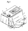
- FIG. 1 shows a drum weigher having a stainless steel base plate 11, a die-cast cover or enclosure 12 covering just over half of the base plate, a low circular weighing capsule 13 disposed centrally on the uncovered area of the base plate and a sloping drum back-stop 14 covering something less than half of the weighing capsule at the side thereof next the cover 12.
- the cover 12 houses the electronic circuitry of the weigher and provides at its top face a control and read-out console having an on/off switch 15, a read-out panel 16 giving a display, for example a liquid crystal display, in figures of the load weighed, and an adjustment knob 11 operating a potentiometer for adjusting the tare weight to which the instrument is set.
- the back-stop 14 is made by bending stainless steel sheet and has a front face 18 with its lower edge 19 lying across the weighing capsule 13, a short distance above it, leaving the centre of the capsule uncovered. From its lower edge 19, the front face of the back-stop extends upwardly with a backward slope toward the cover 12. At its ends the back-stop 14 has vertical support walls 20 extending down to brackets 21 that are secured to the base plate 11.
- the securing is by means of screws 22 in slotted holes 23 allowing adjustment of the back-stop toward and away from the cover 11.
- the amount of available adjustment is 8 mm.
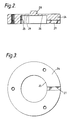
- FIGs 2 and 3 show the weighing capsule 13, made of Carr's P576 or equivalent. In manufacture, it is hardened and tempered and then zinc plated.
- the capsule consists of a circular disc 24 which, in the example shown is 50 mm in diameter and 8.5 mm thick, with a central blind bore 25, 25 mm in diameter and 7.3 mm deep, to leave a diaphragm 26, 1.2 mm thick, spanning the blind end of the bore.
- This capsule is screwed to the base-plate 11 with the open end of the bore 24 downward.
- the capsule has a channel 27 through the lower part of the circular portion of it surrounding the bore 25, to vent the interior and give access for electrical leads.
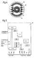
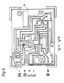
- strain gauges on the diaphragm of the weighing capsule are connected by circuit leads (not shown) passing through the channel 27 to a printed circuit board 34 housed inside the cover 12 and the details of which are shown in Figures 5 and 6.
- the drum weigher described is of compact and rugged construction and is simple to use.
- the sloping back-stop 14 helps the edge of a drum to slide down into the correct position for weighing on the domed head 28. Loads up to 250 kg can be weighed with a tare weight adjustment of ⁇ 50 kg, the accuracy of weighing the drum contents being ⁇ 2%.
- the circuitry is battery powered making the drum weigher entirely portable.
Landscapes
- Physics & Mathematics (AREA)
- General Physics & Mathematics (AREA)
- Weight Measurement For Supplying Or Discharging Of Specified Amounts Of Material (AREA)
- Nozzles (AREA)
Claims (8)
- Balance pour ballons, tonneaux et charges analogues comprenant une base (11) pour reposer sur le sol, un support de charge prévu sur la base à une faible hauteur par rapport au sol, un organe de repos porté sur le support de charge et sur lequel un point situé autour de la bordure inférieure d'un ballon ou analogue devant être pesé doit être reposé, le point diamétralement opposé de la bordure inférieure du ballon reposant sur le sol, la charge due au poids étant mesurée, à l'aide de jauges de contraintes, placées sur le support, reliées à des éléments composant un circuit électrique, pour fournir un signal électrique qui varie suivant la charge, et une butée arrière du ballon prévu à l 'opposé du côté de la paroi de la partie de périphérie inférieure du ballon qui repose sur le support de charge, caractérisée en ce que le support de charge est une capsule de pesage (13) comprenant un diaphragme à disque (26) disposé horizontalement, les jauges de contraintes (30 à 33) étant placées sel on un réseau sur la surface du diaphragme, l'organe de repos étant une tête de support (28) située debout depuis le côté supérieur du diaphragme, au centre de celui-ci, et la butée arrière du ballon (14) s'étend par dessus la capsule de pesage immédiatement au-dessus de la tête de support, de manière à aider à placer la bordure du ballon en position correcte sur la tête de support pour obtenir un pesage précis.
- Balance selon la revendication 1, dans laquelle la capsule de pesage est formée par un disque circulaire (24) qui présente un alésage borgne central (25) le diaphragme exerçant une contrainte sur l'extrémité borgne de l'alésage, le disque de capsule étant monté horizontalement avec l'extrémité ouverte de l'alésage dirigée vers le bas et le diaphragme étant situé au-dessus, et le modèle formé par les jauges de contraintes étant placé sur la face inférieure du diaphragme.
- Balance selon le revendication 2, dans laquelle la tête de support est formée d'une seule pièce sur la face supérieure du diaphragme et est bombée et creusée.
- Balance selon la revendication 2 ou 3, dans laquelle la partie annulaire du disque de capsule entourant l'alésage présente un canal radial (27) traversant pour l'échappement de l'air et fournir un accès pour des conducteurs électriques.
- Balance selon l'une quelconque des revendications précédentes, dans laquelle la butée arrière comprend une paroi (18) s'étendant en s'écartant vers le haut, depuis la capsule, et étant aussi incliné vers l'arrière dans la direction ascendante par rapport à un ballon reposant sur la tête de support.
- Balance selon l'une quelconque des revendications précédentes, dans laquelle la butée est ajustable horizontal ement en s'approchant et en s'éloignant du centre de la capsule.
- Balance selon l'une quelconque des revendications précédentes comprenant en outre des moyens de commande (11) pour régler la tare d'un ballon ou d'une charge analogue à peser, pour que le poids du contenu du ballon puisse être indiqué.
- Balance selon l'une quelconque des revendications précédentes, dans laquelle les éléments composant un circuit électrique (34) fonctionnent grâce à une batterie.
Applications Claiming Priority (2)
| Application Number | Priority Date | Filing Date | Title |
|---|---|---|---|
| GB868624340A GB8624340D0 (en) | 1986-10-10 | 1986-10-10 | Drum weigher |
| GB8624340 | 1986-10-10 |
Publications (3)
| Publication Number | Publication Date |
|---|---|
| EP0263717A2 EP0263717A2 (fr) | 1988-04-13 |
| EP0263717A3 EP0263717A3 (en) | 1988-07-06 |
| EP0263717B1 true EP0263717B1 (fr) | 1991-09-25 |
Family
ID=10605548
Family Applications (1)
| Application Number | Title | Priority Date | Filing Date |
|---|---|---|---|
| EP87308962A Expired - Lifetime EP0263717B1 (fr) | 1986-10-10 | 1987-10-09 | Balance pour tonneaux |
Country Status (5)
| Country | Link |
|---|---|
| US (1) | US4776414A (fr) |
| EP (1) | EP0263717B1 (fr) |
| AU (1) | AU598594B2 (fr) |
| DE (1) | DE3773321D1 (fr) |
| GB (1) | GB8624340D0 (fr) |
Families Citing this family (10)
| Publication number | Priority date | Publication date | Assignee | Title |
|---|---|---|---|---|
| FR2630544B1 (fr) * | 1988-04-21 | 1990-07-13 | Ficheux Rene | Dispositif de pesee pour mesurer la charge dans les cabines d'ascenseurs |
| USD331885S (en) | 1989-09-15 | 1992-12-22 | Badcock Francis D M | Combination crane hook and weighing instrument |
| USD337538S (en) | 1990-03-06 | 1993-07-20 | Badcock Francis D M | Load weighing device |
| CH680877A5 (fr) * | 1990-05-23 | 1992-11-30 | Mettler Toledo Ag | |
| US5313022A (en) * | 1992-11-12 | 1994-05-17 | Kistler-Morse Corporation | Load cell for weighing the contents of storage vessels |
| DE10342479B4 (de) * | 2002-09-17 | 2016-03-31 | Harmonic Drive Systems Inc. | Drehmomentdetektionsvorrichtung für Wellengetriebe |
| JP4518467B2 (ja) * | 2002-09-17 | 2010-08-04 | 株式会社ハーモニック・ドライブ・システムズ | 波動歯車装置のトルク検出装置 |
| US7210362B2 (en) * | 2002-11-05 | 2007-05-01 | Tanita Corporation | Diaphragm type load detection sensor, load detection unit and electronic scale using same |
| WO2008003168A1 (fr) * | 2006-07-05 | 2008-01-10 | Simons Gerald S | Cellule de charge avec base a surface incurvée |
| JP7271577B2 (ja) * | 2019-01-18 | 2023-05-11 | ニデックドライブテクノロジー株式会社 | トルク検出センサおよび動力伝達装置 |
Citations (1)
| Publication number | Priority date | Publication date | Assignee | Title |
|---|---|---|---|---|
| GB2127980A (en) * | 1982-06-30 | 1984-04-18 | William Cairnes | Measuring contents of containers |
Family Cites Families (10)
| Publication number | Priority date | Publication date | Assignee | Title |
|---|---|---|---|---|
| AU415011B2 (en) * | 1966-11-14 | 1971-07-07 | Portable scales | |
| US4047584A (en) * | 1976-07-08 | 1977-09-13 | Daly Richard T | Bee-hive scale |
| DE2729064C2 (de) * | 1977-06-28 | 1985-04-11 | Philips Patentverwaltung Gmbh, 2000 Hamburg | Symmetrische flache Kraftmeßzelle |
| GB1588512A (en) * | 1977-07-11 | 1981-04-23 | Autoweigh Weighing Machines Lt | Weighing |
| US4319651A (en) * | 1980-04-28 | 1982-03-16 | Kenneth Robichaud | Weighing device |
| GB2078982B (en) * | 1980-06-28 | 1985-06-26 | Hearn Geoffrey | Bottle gauge |
| US4480737A (en) * | 1981-03-12 | 1984-11-06 | Ara Services, Inc. | Apparatus for recognizing, crushing separating, weighing and making payment for, used metal items, particularly aluminum cans |
| US4474255A (en) * | 1983-04-14 | 1984-10-02 | Blok Stephen A | Beer keg scale |
| WO1985001576A1 (fr) * | 1983-09-28 | 1985-04-11 | William Cairnes | Appareil de mesure du contenu d'un recipient |
| NL8401420A (nl) * | 1984-05-04 | 1985-12-02 | Philips Nv | Weegelement voor een weegtoestel. |
-
1986
- 1986-10-10 GB GB868624340A patent/GB8624340D0/en active Pending
-
1987
- 1987-10-09 AU AU79594/87A patent/AU598594B2/en not_active Ceased
- 1987-10-09 EP EP87308962A patent/EP0263717B1/fr not_active Expired - Lifetime
- 1987-10-09 DE DE8787308962T patent/DE3773321D1/de not_active Expired - Fee Related
- 1987-10-13 US US07/107,091 patent/US4776414A/en not_active Expired - Fee Related
Patent Citations (1)
| Publication number | Priority date | Publication date | Assignee | Title |
|---|---|---|---|---|
| GB2127980A (en) * | 1982-06-30 | 1984-04-18 | William Cairnes | Measuring contents of containers |
Also Published As
| Publication number | Publication date |
|---|---|
| AU598594B2 (en) | 1990-06-28 |
| EP0263717A2 (fr) | 1988-04-13 |
| AU7959487A (en) | 1988-04-14 |
| GB8624340D0 (en) | 1986-11-12 |
| US4776414A (en) | 1988-10-11 |
| DE3773321D1 (de) | 1991-10-31 |
| EP0263717A3 (en) | 1988-07-06 |
Similar Documents
| Publication | Publication Date | Title |
|---|---|---|
| EP0670480B1 (fr) | Appareil de mesure de charge | |
| US7202424B2 (en) | Balance control system for weight scales | |
| US4177868A (en) | Weight-measuring and display device | |
| US4776414A (en) | Drum weigher | |
| US4372405A (en) | Weight, volume or density measuring system | |
| US3134451A (en) | Platform type bathroom scale | |
| US6761683B2 (en) | Integrated scale with underlying x-ray tray | |
| US7126065B2 (en) | Weighing scale adapted for allowing a user to find an optical weighing position on the scale | |
| WO2001009571A2 (fr) | Pelle pourvue d'une balance | |
| US5994649A (en) | Portable weighing device for the mobility-disabled | |
| US6777625B2 (en) | Balance with antenna for querying weighed objects having transponders | |
| ES2010309A6 (es) | Aparato para pesar y tallar personas. | |
| US4153125A (en) | Digital electronic scale | |
| EP0348824A3 (fr) | Balance électronique | |
| US4512429A (en) | Weighing apparatus for producing geographically-corrected measurements | |
| US4174760A (en) | Scale construction | |
| US4712627A (en) | Calibration of weight scale utilizing a capacitative load cell | |
| US4832142A (en) | Electronic scale apparatus | |
| JP2004347452A (ja) | 重量測定装置 | |
| US3791467A (en) | Scale having a restrained movable balancing member | |
| JPS58112Y2 (ja) | 台はかり | |
| JP3279052B2 (ja) | 電子天びん | |
| EP1400791B1 (fr) | Dispositif de pesage | |
| RU212837U1 (ru) | Электронные весы | |
| SU830133A1 (ru) | Весовое устройство |
Legal Events
| Date | Code | Title | Description |
|---|---|---|---|
| PUAI | Public reference made under article 153(3) epc to a published international application that has entered the european phase |
Free format text: ORIGINAL CODE: 0009012 |
|
| AK | Designated contracting states |
Kind code of ref document: A2 Designated state(s): BE DE FR GB IT LU NL |
|
| PUAL | Search report despatched |
Free format text: ORIGINAL CODE: 0009013 |
|
| AK | Designated contracting states |
Kind code of ref document: A3 Designated state(s): BE DE FR GB IT LU NL |
|
| 17P | Request for examination filed |
Effective date: 19881112 |
|
| 17Q | First examination report despatched |
Effective date: 19890206 |
|
| GRAA | (expected) grant |
Free format text: ORIGINAL CODE: 0009210 |
|
| AK | Designated contracting states |
Kind code of ref document: B1 Designated state(s): BE DE FR GB IT LU NL |
|
| PG25 | Lapsed in a contracting state [announced via postgrant information from national office to epo] |
Ref country code: IT Free format text: LAPSE BECAUSE OF FAILURE TO SUBMIT A TRANSLATION OF THE DESCRIPTION OR TO PAY THE FEE WITHIN THE PRE;WARNING: LAPSES OF ITALIAN PATENTS WITH EFFECTIVE DATE BEFORE 2007 MAY HAVE OCCURRED AT ANY TIME BEFORE 2007. THE CORRECT EFFECTIVE DATE MAY BE DIFFERENT FROM THE ONE RECORDED.SCRIBED TIME-LIMIT Effective date: 19910925 Ref country code: BE Effective date: 19910925 Ref country code: NL Effective date: 19910925 |
|
| PG25 | Lapsed in a contracting state [announced via postgrant information from national office to epo] |
Ref country code: LU Free format text: LAPSE BECAUSE OF NON-PAYMENT OF DUE FEES Effective date: 19911031 |
|
| REF | Corresponds to: |
Ref document number: 3773321 Country of ref document: DE Date of ref document: 19911031 |
|
| ET | Fr: translation filed | ||
| NLV1 | Nl: lapsed or annulled due to failure to fulfill the requirements of art. 29p and 29m of the patents act | ||
| PLBE | No opposition filed within time limit |
Free format text: ORIGINAL CODE: 0009261 |
|
| STAA | Information on the status of an ep patent application or granted ep patent |
Free format text: STATUS: NO OPPOSITION FILED WITHIN TIME LIMIT |
|
| 26N | No opposition filed | ||
| PGFP | Annual fee paid to national office [announced via postgrant information from national office to epo] |
Ref country code: GB Payment date: 19951002 Year of fee payment: 9 |
|
| PGFP | Annual fee paid to national office [announced via postgrant information from national office to epo] |
Ref country code: FR Payment date: 19951010 Year of fee payment: 9 |
|
| PGFP | Annual fee paid to national office [announced via postgrant information from national office to epo] |
Ref country code: DE Payment date: 19951012 Year of fee payment: 9 |
|
| PG25 | Lapsed in a contracting state [announced via postgrant information from national office to epo] |
Ref country code: GB Effective date: 19961009 |
|
| GBPC | Gb: european patent ceased through non-payment of renewal fee |
Effective date: 19961009 |
|
| PG25 | Lapsed in a contracting state [announced via postgrant information from national office to epo] |
Ref country code: FR Effective date: 19970630 |
|
| PG25 | Lapsed in a contracting state [announced via postgrant information from national office to epo] |
Ref country code: DE Effective date: 19970701 |
|
| REG | Reference to a national code |
Ref country code: FR Ref legal event code: ST |