EP0263820B1 - Dispositif de blocageentre deux elements - Google Patents
Dispositif de blocageentre deux elements Download PDFInfo
- Publication number
- EP0263820B1 EP0263820B1 EP86903689A EP86903689A EP0263820B1 EP 0263820 B1 EP0263820 B1 EP 0263820B1 EP 86903689 A EP86903689 A EP 86903689A EP 86903689 A EP86903689 A EP 86903689A EP 0263820 B1 EP0263820 B1 EP 0263820B1
- Authority
- EP
- European Patent Office
- Prior art keywords
- sleeve
- bridges
- sections
- locking
- rows
- Prior art date
- Legal status (The legal status is an assumption and is not a legal conclusion. Google has not performed a legal analysis and makes no representation as to the accuracy of the status listed.)
- Expired - Lifetime
Links
- 230000000694 effects Effects 0.000 claims abstract description 21
- 239000000463 material Substances 0.000 claims abstract description 14
- 230000006835 compression Effects 0.000 claims abstract description 9
- 238000007906 compression Methods 0.000 claims abstract description 9
- 238000003780 insertion Methods 0.000 claims abstract 3
- 230000037431 insertion Effects 0.000 claims abstract 3
- 238000000034 method Methods 0.000 claims description 9
- 238000006073 displacement reaction Methods 0.000 claims description 6
- 230000015572 biosynthetic process Effects 0.000 claims 2
- 238000004519 manufacturing process Methods 0.000 abstract description 2
- 230000035882 stress Effects 0.000 description 3
- 238000007514 turning Methods 0.000 description 3
- 239000002184 metal Substances 0.000 description 2
- 239000000843 powder Substances 0.000 description 2
- 230000008961 swelling Effects 0.000 description 2
- 230000032683 aging Effects 0.000 description 1
- 238000005452 bending Methods 0.000 description 1
- 238000010276 construction Methods 0.000 description 1
- 238000005260 corrosion Methods 0.000 description 1
- 230000007797 corrosion Effects 0.000 description 1
- 238000009826 distribution Methods 0.000 description 1
- 238000005516 engineering process Methods 0.000 description 1
- 238000007373 indentation Methods 0.000 description 1
- 238000003754 machining Methods 0.000 description 1
- 230000009972 noncorrosive effect Effects 0.000 description 1
- 239000002861 polymer material Substances 0.000 description 1
- 230000035945 sensitivity Effects 0.000 description 1
- 210000002105 tongue Anatomy 0.000 description 1
- 238000009827 uniform distribution Methods 0.000 description 1
Images

Classifications
-
- F—MECHANICAL ENGINEERING; LIGHTING; HEATING; WEAPONS; BLASTING
- F16—ENGINEERING ELEMENTS AND UNITS; GENERAL MEASURES FOR PRODUCING AND MAINTAINING EFFECTIVE FUNCTIONING OF MACHINES OR INSTALLATIONS; THERMAL INSULATION IN GENERAL
- F16D—COUPLINGS FOR TRANSMITTING ROTATION; CLUTCHES; BRAKES
- F16D1/00—Couplings for rigidly connecting two coaxial shafts or other movable machine elements
- F16D1/06—Couplings for rigidly connecting two coaxial shafts or other movable machine elements for attachment of a member on a shaft or on a shaft-end
- F16D1/08—Couplings for rigidly connecting two coaxial shafts or other movable machine elements for attachment of a member on a shaft or on a shaft-end with clamping hub; with hub and longitudinal key
- F16D1/0829—Couplings for rigidly connecting two coaxial shafts or other movable machine elements for attachment of a member on a shaft or on a shaft-end with clamping hub; with hub and longitudinal key with radial loading of both hub and shaft by an intermediate ring or sleeve
- F16D1/0841—Couplings for rigidly connecting two coaxial shafts or other movable machine elements for attachment of a member on a shaft or on a shaft-end with clamping hub; with hub and longitudinal key with radial loading of both hub and shaft by an intermediate ring or sleeve due to axial loading of the ring or sleeve, e.g. Belleville washers
-
- F—MECHANICAL ENGINEERING; LIGHTING; HEATING; WEAPONS; BLASTING
- F16—ENGINEERING ELEMENTS AND UNITS; GENERAL MEASURES FOR PRODUCING AND MAINTAINING EFFECTIVE FUNCTIONING OF MACHINES OR INSTALLATIONS; THERMAL INSULATION IN GENERAL
- F16D—COUPLINGS FOR TRANSMITTING ROTATION; CLUTCHES; BRAKES
- F16D1/00—Couplings for rigidly connecting two coaxial shafts or other movable machine elements
- F16D1/06—Couplings for rigidly connecting two coaxial shafts or other movable machine elements for attachment of a member on a shaft or on a shaft-end
- F16D1/064—Couplings for rigidly connecting two coaxial shafts or other movable machine elements for attachment of a member on a shaft or on a shaft-end non-disconnectable
- F16D1/072—Couplings for rigidly connecting two coaxial shafts or other movable machine elements for attachment of a member on a shaft or on a shaft-end non-disconnectable involving plastic deformation
-
- Y—GENERAL TAGGING OF NEW TECHNOLOGICAL DEVELOPMENTS; GENERAL TAGGING OF CROSS-SECTIONAL TECHNOLOGIES SPANNING OVER SEVERAL SECTIONS OF THE IPC; TECHNICAL SUBJECTS COVERED BY FORMER USPC CROSS-REFERENCE ART COLLECTIONS [XRACs] AND DIGESTS
- Y10—TECHNICAL SUBJECTS COVERED BY FORMER USPC
- Y10T—TECHNICAL SUBJECTS COVERED BY FORMER US CLASSIFICATION
- Y10T403/00—Joints and connections
- Y10T403/70—Interfitted members
- Y10T403/7047—Radially interposed shim or bushing
- Y10T403/7051—Wedging or camming
- Y10T403/7052—Engaged by axial movement
- Y10T403/7056—Threaded actuator
-
- Y—GENERAL TAGGING OF NEW TECHNOLOGICAL DEVELOPMENTS; GENERAL TAGGING OF CROSS-SECTIONAL TECHNOLOGIES SPANNING OVER SEVERAL SECTIONS OF THE IPC; TECHNICAL SUBJECTS COVERED BY FORMER USPC CROSS-REFERENCE ART COLLECTIONS [XRACs] AND DIGESTS
- Y10—TECHNICAL SUBJECTS COVERED BY FORMER USPC
- Y10T—TECHNICAL SUBJECTS COVERED BY FORMER US CLASSIFICATION
- Y10T403/00—Joints and connections
- Y10T403/70—Interfitted members
- Y10T403/7047—Radially interposed shim or bushing
- Y10T403/7061—Resilient
Definitions
- the present invention relates to a device for locking two elements whose surfaces face each other, and between which surfaces the device is designed to be inserted and manoeuvred into a position which produces the said locking or braking effect.
- Such elements as for example described in SE-B-320550, comprise a shaft and a hub liner with concentric cylindrical surfaces, between which it is desired to form a friction joint and/or shear strain, or a controlled braking effect.
- a primary demand with regard to shaft connections is that the connection should transmit as much torque or load as possible in relation to the shaft dimension.
- the outer and inner diameters of the hub should also be as small as possible in relation to the size of the shaft, and, where possible, the stress produced upon the shaft and the hub should be uniform. In this way, the minimum extemal dimensions and the lowest weight are achieved.
- An important aspect is the requirement for a uniform distribution of pressure over relatively large areas of the joint.
- the demands upon both the dimensional and positional tolerances and the surface fineness of the machine components should be moderate. Costly machining of keyways, cones, shoulders and holes for stop bolts etc. should be avoided.
- Mounting of the locking device should be carried out quickly and easily without special tools or any specialist knowledge of the handling of the device. Nor especially should mounting result in any positional shift of the machine parts which are to be connected to the device. A requirement is thus, that the frictional drag and surface pressure etc. which arise during the locking fast of the device should, to as small degree as possible, limit the manoeuvrability of the device during mounting and locking.
- the locking effect of the device should, further, not be affected by external loads, whatever their direction. Nor should there be any significant sensitivity to high or low temperatures, ageing or any normal stresses and strains. It is, in addition, an advantage if the setting or locking position of the device can be checked from outside the device. Finally, a satisfactory locking device should be able to be removed easily in order to free the previously connected components.
- the device should also be cheap and economical with resources, even if the device ought, for noncorrosive purposes, to be produced from a high- grade, corrosion-resistant material.
- the object of the invention is to produce a device which fulfils all of the above demands and requirements, and this object is achieved by a device, the characteristics of which are given in the appended patent claims.
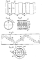
- Fig. 1 is a plan view of an outspread sleeve wall which is part of a locking bush designed in accordance with the invention
- Fig. 2 is an end view of the locking bush
- Fig. 3 shows the locking bush in Figs. 1 and 2 mounted between a shaft and a hub.
- Fig. 4 is a plan view of an outspread sleeve wall which is part of a second design of a locking bush according to the invention.
- Fig. 5 is a longitudinal section of the locking bush according to the second design.
- FIG. 6 is a plan view of an outspread sleeve wall which is part of a third design of locking bush according to the invention.
- Fig. 7 is a plan view of an outspread sleeve wall which is part of a fourth design of locking bush according to the invention.
- Fig. 8 is a cross section of the locking bush according to the fourth design.
- Fig. 9 shows a design variant of the invention formed as a locking plate.
- FIGs. 1-3 A first design of the invention and its use can be seen in Figs. 1-3.
- the device according to this design can be made from either a thin-walled, calibrated tube or a metal strip (Fig. 1), which has been worked and formed into a sleeve.
- Fig. 1 In the body surface 1 of the sleeve are arranged rows 2-7 of compressive, bending and tensile load-absorbing bridges 8, which are punched out and partially freed from the body surface 1 with holes 8a on either side.
- the rows 2-7 extend along substantially the entire length of the sleeve and are, at least partially, orientated in its longitudinal direction.
- the said bridges 8 connect continuous sections 9-14 of the sleeve's body wall 1.
- the sleeve wall 1 is further provided with cross members 15, 16 at the ends of the sleeve. These cross members are so arranged in the design shown that the lower cross members 15 connect the odd-numbered sleeve sections, i. e. sections 9, 11 and 13, while the upper cross members 16 connect the even-numbered sleeve sections, i. e. sections 10, 12 and 14. Through the arrangement of the said rows of bridges 8 and holes, the cross members 15, 16 and the sleeve sections connected thereto, may be displaced relative to each other either axially and/or circumferentially.
- Sleeve sections 9-14 are curtailed at their free ends by long slots 9a-14a which extend circumferentially. The purpose of these slots is to act as a stop upon the axial displacement of sleeve sections 9, 11 and 13 to sleeve sections 10, 12 and 14.
- the body wall is also provided with grip holes 17 in order to remove the device.
- Fig. 3 which shows the method of use for the sleeve shown outspread in Fig. 1, shows thus the sleeve inserted between the two concentric cylindrical surfaces of a shaft 20 and a hub 21.
- the other end of the sleeve, i. e. the end where cross members 15 are, rests against a tightening plate 23, through which there is a central tightening bolt 24, which is in engagement with a threaded hole 26 in the end 25 of the shaft 20.
- the sleeve is initially inserted in its original condition in the space between the said concentric surfaces, after which the tightening plate 23 and the bolt 24 are applied to the end of the shaft 25.
- the thickness of the sleeve is such that it substantially corresponds to the radial play between the shaft 20 and the hub 21.
- the plate 23 is drawn to the left in Fig. 3 by tightening the bolt 24.
- Sleeve sections 9, 11 and 13 will then be displaced axially in relation to sections 10, 12 and 14, in the direction of the shoulder 22.
- the shoulder 22 prevents the displacement of the inner sleeve sections 10, 12 and 14 in relation to the shaft 20 and the hub 21 during the locking procedure.
- sleeve sections 9, 11 and 13 are generally termed the working sections, while sections 10, 12 and 14 are generally termed the contact sections.
- the body wall is provided with weak zones connected with the contact sections.
- these coincide with the bridge ends 27, which connect the bridges 8 with the contact sections 10, 12 and 14.
- the bridge ends 27 are narrower in the plane of the body wall 1 transverse to the long direction of the bridges 8 than the corresponding bridge ends 28 opposite, which connect the bridges 8 to the working sections 9, 11 and 13.
- the pressure points or pressure surfaces 29 should be set up in the device in such a way that they do not to any significant degree change their position relative to the components they press against, or relative to the stationary contact sections. A positional change of the pressure points could otherwise prevent, after a certain degree of expansion and locking has been achieved, any further locking operations, and thereby limit the locking effect of the device. It is therefore suitable that the bridge ends 28 connected to the working sections 9, 11 and 13 are of reduced thickness in comparison with the other parts of the body wall 1, so that these bridge ends 28 do not form pressure points during the locking process. Where great tightening pressure is applied to the tightening plate 23, then pressure points will, naturally, occur at other places than the said bridge ends 27 of reduced width.
- Figs. 4 and 5 show a simpler design, where the bridges 8 and the bridge ends 27 and 28, in principle, coincide, the holes 8a having been formed as circular openings in the body wall 1.
- the grouping of these is such that each row of holes and bridges is inclined in relation to the longitudinal direction of the sleeve.
- Fig. 6 which shows a third design of the locking bush according to the invention
- the holes 8a are formed as long, slanting openings, cuts or laser-cut slots
- the body 1 is provided at both ends of the sleeve with dovetail-shaped portions 30 or holes 17, which form fastening points for dismounting tools or the like, and with which the sleeve sections can be displaced axially for the removal of the sleeve.
- cross members 15 and 16 are not necessary for its function, and these cross members are therefore not included in the design according to Fig. 6.
- a multilinear contact is achieved, unlike the multipoint contact with adjacent surfaces described above.
- Such a variant is shown in Figs. 7 and 8, in which the bridges 8 are elongated and slanted in relation to the axial direction of the sleeve, and are very flexibly connected to the sleeve sections.
- the contact sections, called 10 and 12 in Fig. 7, and which are designed to rest against a shoulder 22 or the like on the shaft, do not undergo any axial or radial displacement during the locking process. They are therefore corrugated or wave-shaped parallel to the longitudinal direction, between the joints or connecting points 27 of the bridges 8, with one or more waves or raised ridges 31.
- Fig. 9 shows a variant in which the rows of holes and bridges are inclined and where alternate rows are inclined in opposite directions in relation to the axial direction of the sleeve.
- the holes are here so formed that the bridges are orientated axially.
- the bridges Upon the compression of the sleeve, the bridges will be directly affected by the axially directed forces on the sleeve, and will thereby achieve the desired locking effect.
- One or more rows of slots 8a and bridges 8 can, if arranged according to the concept of the invention described above, by the relative turning of the inner 40 and outer 43 parts of the disc, produce a number of pressure and friction points projecting at right angles to the disc, which are designed to hinder or prevent displacement between adjacent machine components or the like, between which the disc 40 has been employed in the locked position.
- many different materials may be used, for example, metal strip, tubes, bars, powder or polymer material, injection-moulded or pressed to the desired form, as well as pressed and/or sintered powder material.
- the device For the distribution and/or evening-out of pressure against the components adjacent to the device, it can be an advantage to provide the device with an internal and external lining or casing of suitable thickness and material, which is designed to distribute the loads from the pressure points 29/pressure lines 31 over larger surface areas.
- bridges and/or the bridge ends are whole or unbroken in direct contact with the adjacent material sections.
- One or more of these bridges may be cut off or broken and yet still, through the application of the concept of the invention, achieve the intended effect.
- the number, shape and attitude of the bridges/bridge ends can, in addition, vary in accordance with the construction and purpose of the device, whilst retaining the essential nature of the invention.
- the function of the device can in general be explained in the following terms.
- the many pressure points which engage the surrounding surfaces for example, a hub and a shaft, exert a high specific pressure.
- the locking effect against displacement forces from outside is a product of this pressure and the frictional coefficient of the material in question.
- a locking effect is also obtained from the indentations which occur in the surrounding material and the shear forces thereby created. This shear force resistance from the points can prevent bearing ring movement on the shaft, which is otherwise difficult to control.
Landscapes
- Engineering & Computer Science (AREA)
- General Engineering & Computer Science (AREA)
- Mechanical Engineering (AREA)
- Braking Arrangements (AREA)
- Mutual Connection Of Rods And Tubes (AREA)
Abstract
Claims (10)
Priority Applications (1)
| Application Number | Priority Date | Filing Date | Title |
|---|---|---|---|
| AT86903689T ATE49794T1 (de) | 1985-06-07 | 1986-06-06 | Anordnung zur verbindung von zwei elementen. |
Applications Claiming Priority (2)
| Application Number | Priority Date | Filing Date | Title |
|---|---|---|---|
| SE8502812A SE455334B (sv) | 1985-06-07 | 1985-06-07 | Anordning for astadkommande av las- eller bromsverkan mellan tva element |
| SE8502812 | 1985-06-07 |
Publications (2)
| Publication Number | Publication Date |
|---|---|
| EP0263820A1 EP0263820A1 (fr) | 1988-04-20 |
| EP0263820B1 true EP0263820B1 (fr) | 1990-01-24 |
Family
ID=20360477
Family Applications (1)
| Application Number | Title | Priority Date | Filing Date |
|---|---|---|---|
| EP86903689A Expired - Lifetime EP0263820B1 (fr) | 1985-06-07 | 1986-06-06 | Dispositif de blocageentre deux elements |
Country Status (6)
| Country | Link |
|---|---|
| US (1) | US4906125A (fr) |
| EP (1) | EP0263820B1 (fr) |
| AU (1) | AU589194B2 (fr) |
| DE (1) | DE3668485D1 (fr) |
| SE (1) | SE455334B (fr) |
| WO (1) | WO1986007420A1 (fr) |
Families Citing this family (3)
| Publication number | Priority date | Publication date | Assignee | Title |
|---|---|---|---|---|
| WO1996039591A1 (fr) * | 1995-06-06 | 1996-12-12 | Reliance Electric Industrial Company | Montage adaptable servant a raccorder un arbre au moyeu d'un reducteur de vitesse |
| US5667333A (en) * | 1995-06-30 | 1997-09-16 | Reliance Electric Industrial Company | Shaft-carried speed reducer having adaptable mounting arrangement |
| US9353783B2 (en) * | 2013-03-15 | 2016-05-31 | Rolls-Royce Canada, Ltd. | Auxetic locking pin |
Family Cites Families (14)
| Publication number | Priority date | Publication date | Assignee | Title |
|---|---|---|---|---|
| DE1031584B (de) * | 1952-02-20 | 1958-06-04 | Ringspann Maurer Kg A | Radialspannelement |
| BE665412A (fr) * | 1964-06-17 | 1965-10-01 | ||
| DE1450933A1 (de) * | 1965-12-09 | 1970-01-15 | Karl Breuer | Kraftschluessige Verbindung |
| DE2018367B1 (de) * | 1970-04-16 | 1971-07-29 | Deutsche Star Kugelhalter Gmbh, 8720 Schweinfurt | Verbindungselement fur eine Kupplung mit Klemmbuchse zum Befestigen einer Nabe auf einer Welle |
| US3888598A (en) * | 1973-12-11 | 1975-06-10 | David Samiran | Multiple coil wire lock arrangement |
| DE2507456C3 (de) * | 1975-02-21 | 1981-01-08 | Rudolf 7300 Esslingen Spieth | Spannvorrichtung |
| US3995967A (en) * | 1975-08-13 | 1976-12-07 | Michigan Powdered Metal Products, Inc. | Simultaneously expanding and contracting annular coupling device |
| DE2715418C3 (de) * | 1977-04-06 | 1981-11-19 | Emuge-Werk Richard Glimpel Fabrik für Präzisionswerkzeuge vormals Moschkau & Glimpel, 8560 Lauf | Spannhülse mit gegenläufigen Schlitzen |
| US4480490A (en) * | 1981-10-22 | 1984-11-06 | Inoue-Japax Research Incorporated | Mechanical member |
| CA1195133A (fr) * | 1982-01-29 | 1985-10-15 | James J. Mckenna | Dispositif helicoidal d'accouplement |
| DE3243598A1 (de) * | 1982-11-25 | 1984-05-30 | Festo-Maschinenfabrik Gottlieb Stoll, 7300 Esslingen | Traeger fuer endlos-schleifhuelse |
| DK430983D0 (da) * | 1983-09-21 | 1983-09-21 | Boerge Martins | Elastisk, ringformet spaendeelement |
| GB8404519D0 (en) * | 1984-02-21 | 1984-03-28 | Automotive Prod Plc | Friction clutch for vehicle |
| NZ209718A (en) * | 1984-09-28 | 1989-01-27 | J H Wier | Pipe connector |
-
1985
- 1985-06-07 SE SE8502812A patent/SE455334B/sv not_active IP Right Cessation
-
1986
- 1986-06-06 AU AU59609/86A patent/AU589194B2/en not_active Ceased
- 1986-06-06 EP EP86903689A patent/EP0263820B1/fr not_active Expired - Lifetime
- 1986-06-06 US US07/030,856 patent/US4906125A/en not_active Expired - Fee Related
- 1986-06-06 DE DE8686903689T patent/DE3668485D1/de not_active Expired - Lifetime
- 1986-06-06 WO PCT/SE1986/000269 patent/WO1986007420A1/fr not_active Ceased
Also Published As
| Publication number | Publication date |
|---|---|
| SE455334B (sv) | 1988-07-04 |
| DE3668485D1 (de) | 1990-03-01 |
| WO1986007420A1 (fr) | 1986-12-18 |
| AU5960986A (en) | 1987-01-07 |
| US4906125A (en) | 1990-03-06 |
| SE8502812D0 (sv) | 1985-06-07 |
| SE8502812L (sv) | 1986-12-08 |
| EP0263820A1 (fr) | 1988-04-20 |
| AU589194B2 (en) | 1989-10-05 |
Similar Documents
| Publication | Publication Date | Title |
|---|---|---|
| EP0373239B1 (fr) | Anneau ondulé et feuille d'entretoise | |
| US4268185A (en) | Mounting attachment | |
| KR100501208B1 (ko) | 자유 작동식 토오크 너트 | |
| US5785357A (en) | Locking joint | |
| CA1079326A (fr) | Pieces rapportees de forme conique | |
| US5253947A (en) | Connection between a tubular shaft made of a fiber composite material and a metal journal, as well as a method of producing such a connection | |
| US4682520A (en) | Mechanically lockable fastener assembly | |
| US6116658A (en) | Counter torque tube connection | |
| GB2156935A (en) | Apparatus for stressing fastener shanks | |
| US3503431A (en) | Safety bolt | |
| WO2001004499B1 (fr) | Boulon aveugle haute resistance a fort serrage uniforme sur une gamme etendue des longueurs a serrer | |
| SE425183B (sv) | Dubbelverkande konkoppling | |
| US4465395A (en) | Polygon connection of a hub with a shaft | |
| JPH0217727B2 (fr) | ||
| GB2026650A (en) | Mounting Parts on Shafts | |
| CA1195133A (fr) | Dispositif helicoidal d'accouplement | |
| US4804288A (en) | Coupling attachment | |
| US4649727A (en) | Rotary driver and swaging tool | |
| EP0617206A2 (fr) | Ecrou à positionnement automatique | |
| US20030063949A1 (en) | Expandable key for interconnecting a shaft and hub | |
| SE419574B (sv) | Axelkoppling | |
| CA1281196C (fr) | Organe axial de retenue, et methode d'interconnexion de pieces cannelees males et femelles | |
| JPH0328601B2 (fr) | ||
| AU589194B2 (en) | Device for the production of a locking or braking effect between two elements | |
| US7309187B2 (en) | Releasable keyless bushing assembly |
Legal Events
| Date | Code | Title | Description |
|---|---|---|---|
| PUAI | Public reference made under article 153(3) epc to a published international application that has entered the european phase |
Free format text: ORIGINAL CODE: 0009012 |
|
| 17P | Request for examination filed |
Effective date: 19871128 |
|
| AK | Designated contracting states |
Kind code of ref document: A1 Designated state(s): AT BE CH DE FR GB IT LI NL |
|
| 17Q | First examination report despatched |
Effective date: 19890421 |
|
| GRAA | (expected) grant |
Free format text: ORIGINAL CODE: 0009210 |
|
| ITF | It: translation for a ep patent filed | ||
| AK | Designated contracting states |
Kind code of ref document: B1 Designated state(s): AT BE CH DE FR GB IT LI NL |
|
| REF | Corresponds to: |
Ref document number: 49794 Country of ref document: AT Date of ref document: 19900215 Kind code of ref document: T |
|
| REF | Corresponds to: |
Ref document number: 3668485 Country of ref document: DE Date of ref document: 19900301 |
|
| ET | Fr: translation filed | ||
| PGFP | Annual fee paid to national office [announced via postgrant information from national office to epo] |
Ref country code: BE Payment date: 19900613 Year of fee payment: 5 Ref country code: AT Payment date: 19900613 Year of fee payment: 5 |
|
| PGFP | Annual fee paid to national office [announced via postgrant information from national office to epo] |
Ref country code: CH Payment date: 19900625 Year of fee payment: 5 |
|
| ITTA | It: last paid annual fee | ||
| PGFP | Annual fee paid to national office [announced via postgrant information from national office to epo] |
Ref country code: NL Payment date: 19900630 Year of fee payment: 5 |
|
| PLBE | No opposition filed within time limit |
Free format text: ORIGINAL CODE: 0009261 |
|
| STAA | Information on the status of an ep patent application or granted ep patent |
Free format text: STATUS: NO OPPOSITION FILED WITHIN TIME LIMIT |
|
| 26N | No opposition filed | ||
| PG25 | Lapsed in a contracting state [announced via postgrant information from national office to epo] |
Ref country code: AT Effective date: 19910606 |
|
| PG25 | Lapsed in a contracting state [announced via postgrant information from national office to epo] |
Ref country code: LI Effective date: 19910630 Ref country code: CH Effective date: 19910630 Ref country code: BE Effective date: 19910630 |
|
| BERE | Be: lapsed |
Owner name: BURSTROM BERTIL Effective date: 19910630 |
|
| PG25 | Lapsed in a contracting state [announced via postgrant information from national office to epo] |
Ref country code: NL Effective date: 19920101 |
|
| NLV4 | Nl: lapsed or anulled due to non-payment of the annual fee | ||
| REG | Reference to a national code |
Ref country code: CH Ref legal event code: PL |
|
| PGFP | Annual fee paid to national office [announced via postgrant information from national office to epo] |
Ref country code: GB Payment date: 19931130 Year of fee payment: 8 |
|
| PGFP | Annual fee paid to national office [announced via postgrant information from national office to epo] |
Ref country code: FR Payment date: 19931222 Year of fee payment: 8 |
|
| PGFP | Annual fee paid to national office [announced via postgrant information from national office to epo] |
Ref country code: DE Payment date: 19940225 Year of fee payment: 8 |
|
| PG25 | Lapsed in a contracting state [announced via postgrant information from national office to epo] |
Ref country code: GB Effective date: 19940606 |
|
| GBPC | Gb: european patent ceased through non-payment of renewal fee |
Effective date: 19940606 |
|
| PG25 | Lapsed in a contracting state [announced via postgrant information from national office to epo] |
Ref country code: FR Effective date: 19950228 |
|
| PG25 | Lapsed in a contracting state [announced via postgrant information from national office to epo] |
Ref country code: DE Effective date: 19950301 |
|
| REG | Reference to a national code |
Ref country code: FR Ref legal event code: ST |
|
| PG25 | Lapsed in a contracting state [announced via postgrant information from national office to epo] |
Ref country code: IT Free format text: LAPSE BECAUSE OF NON-PAYMENT OF DUE FEES Effective date: 20050606 |