EP0263997B1 - Querdrahtzuführung zu einer Gitterschweissmaschine - Google Patents
Querdrahtzuführung zu einer Gitterschweissmaschine Download PDFInfo
- Publication number
- EP0263997B1 EP0263997B1 EP87113733A EP87113733A EP0263997B1 EP 0263997 B1 EP0263997 B1 EP 0263997B1 EP 87113733 A EP87113733 A EP 87113733A EP 87113733 A EP87113733 A EP 87113733A EP 0263997 B1 EP0263997 B1 EP 0263997B1
- Authority
- EP
- European Patent Office
- Prior art keywords
- transverse
- wire
- web plate
- disc
- rotation
- Prior art date
- Legal status (The legal status is an assumption and is not a legal conclusion. Google has not performed a legal analysis and makes no representation as to the accuracy of the status listed.)
- Expired - Lifetime
Links
- 238000003466 welding Methods 0.000 title claims abstract description 42
- 230000002093 peripheral effect Effects 0.000 claims abstract description 4
- 230000006835 compression Effects 0.000 claims description 4
- 238000007906 compression Methods 0.000 claims description 4
- 239000011435 rock Substances 0.000 claims 1
- 238000004519 manufacturing process Methods 0.000 description 3
- 238000000034 method Methods 0.000 description 2
- 238000003860 storage Methods 0.000 description 2
- 238000005520 cutting process Methods 0.000 description 1
- 230000001419 dependent effect Effects 0.000 description 1
- 230000000694 effects Effects 0.000 description 1
- 230000010355 oscillation Effects 0.000 description 1
- 230000000087 stabilizing effect Effects 0.000 description 1
- 230000032258 transport Effects 0.000 description 1
Images
Classifications
-
- B—PERFORMING OPERATIONS; TRANSPORTING
- B23—MACHINE TOOLS; METAL-WORKING NOT OTHERWISE PROVIDED FOR
- B23K—SOLDERING OR UNSOLDERING; WELDING; CLADDING OR PLATING BY SOLDERING OR WELDING; CUTTING BY APPLYING HEAT LOCALLY, e.g. FLAME CUTTING; WORKING BY LASER BEAM
- B23K11/00—Resistance welding; Severing by resistance heating
- B23K11/002—Resistance welding; Severing by resistance heating specially adapted for particular articles or work
- B23K11/008—Manufacturing of metallic grids or mats by spot welding
-
- B—PERFORMING OPERATIONS; TRANSPORTING
- B21—MECHANICAL METAL-WORKING WITHOUT ESSENTIALLY REMOVING MATERIAL; PUNCHING METAL
- B21F—WORKING OR PROCESSING OF METAL WIRE
- B21F27/00—Making wire network, i.e. wire nets
- B21F27/08—Making wire network, i.e. wire nets with additional connecting elements or material at crossings
- B21F27/10—Making wire network, i.e. wire nets with additional connecting elements or material at crossings with soldered or welded crossings
Definitions
- the invention relates to a grid welding machine with a line wire feed and a cross wire feed according to the preamble of claim 1.
- a machine for producing welded wire mesh from longitudinal and transverse wires crossing at right angles with a multi-point welding device is known.
- This machine is equipped with a cross wire magazine in which the cross wires are stacked one behind the other.
- a series of levers are articulated, which are swung upwards after the welding in the area of the intersection by the newly welded cross wire, so that on the one hand the welded wire mesh can be pulled forward, on the other hand the magazine releases a new cross wire which reaches the weld in free fall.
- the production speed of the wire mesh, etc. depends on the feeding speed of the cross wires, which reach the welding point in free fall, then have to be stored there safely.
- the welding electrodes In order to reliably feed the cross wires, the welding electrodes must be lifted relatively far apart, the cross wires must then be positioned in the area of the welding electrodes and only then can the welding electrodes be lowered again and the welding process carried out.
- the production speed of such grids thus depends on the path of the welding electrodes, which they must carry out in order to ensure the correct reception and storage of the cross wire.
- a feed and locking device for cross wires on mesh welding machines has become known, in which the cross wires are guided in receiving spaces of a cross wire feeder disc by means of a web plate.
- the feeder disk then transfers the cross wire to a clamping device formed from the web plate and a counterholder, and the cross wire is guided through the movable upper electrode into a clamping area which is formed by pressure springs.
- a very large electrode stroke is also required, which limits the performance of the machine.
- the invention has for its object to improve the generic grid welding machine so that only a very small electrode stroke is required, whereby the working speed of the entire machine can be improved, and that at the same time the discharge of the cross wire from the receiving space of each cross wire feeder disc to the welding point without a cutting effect the wall of the receiving space is effected on the cross wire.
- the invention therefore proposes that, while maintaining the cross wire feeder disks, the cross wire is no longer stored within the cross wire receiving spaces at the bottom or lowest of the receiving space, but is already raised out of the deepest of the cross wire receiving space during the rotational movement of the cross wire receiving space.
- this cross wire which is in a relatively unstable position and is held only on the one hand by the web plate and on the other hand by the rear wall of the cross wire receiving space, as seen in the direction of rotation of the cross wire feeder disc, is held down by a hold-down device which resiliently presses the cross wire onto the web plate and thereby stabilizing the position of the cross wire.
- the cross wire is thus pinched.
- the cross wire is guided further through the cross wire feed disk into the area of the welding point and comes here against a counterholder, which precisely defines the position of the cross wire.
- the outer peripheral edge of the cross wire feeder disc lies against the cross wire and also holds it in place.
- the cross wire was released from the cross wire receiving space and at this point the upper electrode can move towards the lower electrode and thus weld the cross wire to the longitudinal wire.
- the receiving space between the two electrodes can therefore be set relatively small, so that only a small electrode stroke is required. Of course, this affects the welding speed of the entire grid welding machine.
- the counter-holder is lifted by pulling on the longitudinal wire and thereby releases the weld, similarly to the device according to DE-AS 12 53 215.
- the qued wire feeder disk already transports the next cross wire forward into the area of the electrodes, so that the next cross wire is immediately available for its direct supply to the welding point as soon as the next welding point is reached through the longitudinal wires.
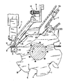
- the drawing shows, relatively schematically, the view of a cross wire feeder disk, it being expressly pointed out that, of course, a large number of such cross wire feeder disks with the associated elements are arranged in alignment on a shaft in succession.
- the cross wire feeder disc 1 denotes a cross wire feed disk, which is arranged on a shaft 2, which rotates in the direction of arrow F.
- the cross wire feeder disc 1 has cross wire receiving spaces 3 which, viewed in the direction of rotation, have a radially directed front wall 4 which is relatively straight and a rear wall 5, the upper region between the rear wall 5 and the circumferential line of the cross wire feeder disc being flattened at 6, namely in the direction of rotation to the rear in alignment.
- FIG. 7 and 8 designate two interacting welding electrodes, the upper welding electrode 7 being able to perform a short stroke in order to expose the welding point or to be guided onto the wires to be welded.
- 9 is a longitudinal wire and 10 is a transverse wire located in the area of the welding point, a further transverse wire 10a being shown in one of the transverse wire receiving spaces 3.
- Another cross wire 10b is discharged into a cross wire receiving space 3 from a cross wire conveyor 11, and finally another cross wire 10c is located on the cross wire conveyor.
- a holding device which carries a counter-holder 14 pivotably on a pivot shaft 12.
- the counter-holder 14 can be pivoted against the force of a compression spring 15, namely pivoted upwards in the drawing, it being shown in its lowest position in the drawing.
- the pivot shaft 12 also carries a hold-down device 16, which is also spring-borne by the pivot shaft 12. Since the hold-down device 16 is covered by the cross wire feeder disk 1 in the illustration, it is shown in dashed lines in the lower region.
- a web plate 17 is provided behind the cross wire feeder disk 1, which is arranged with respect to the cross wire receiving spaces 3 in such a way that the cross wire 10b is raised from its lowest position into the position of the cross wire 10a and undergoes a further lifting in the area shortly before the welding point.
- the cross wire feeder disk 1 preferably rotates constantly.
- the cross wire conveyor 11 is driven and the cross wires 10c carried by the cross wire conveyor 11 are placed in a cross wire receiving space 3 of the cross wire feeder disc 1, as shown for the cross wire 10b.
- the cross wire 10b is brought into the position of the cross wire 10a and is conveyed forward through the rear wall 5 of the receiving space 3, but via the web plate 17 to the actual welding point and thereby being raised further and further from the lowest point of the cross wire receiving space 3.
- the cross wire 10a comes into contact with the hold-down device 16.
- the hold-down device 16 is raised by the cross wire 10a and thereby presses the cross wire onto the web plate 17, i.e. any oscillations or vibrations of the cross wire, which extends over a relatively large length, are thereby canceled.
- the cross wire 10a is clamped between the web plate 17, rear wall 5 and hold-down device 16 and pressed into the position of the cross wire 10.
- the height of the cross wire 10 is thereby limited downwards by the longitudinal wire 9 and it can be seen that the welding electrode 7 only has to be raised by an amount which is slightly larger than that of the cross wire, i.e. the stroke of the welding electrode 7 can be relatively small.
- the cross wire 10 comes into contact with the counterholder 14 and is thereby determined in a precisely determined position, this exact position not only being achieved by free application of the crosswire 10 to the counterholder 14, but at the same time it becomes Cross wire 10 in its position also fixed by the peripheral surface 18 of the cross wire feeder.
- the electrode 7 can move downward and initiate each welding process.
- the welded grid is then pulled forward by a working width and here the welded cross wire 10 pushes the counter-holder 14 upwards, which can move about the pivot shaft 12, with compression of the Compression spring 15.
Landscapes
- Engineering & Computer Science (AREA)
- Mechanical Engineering (AREA)
- Manufacturing & Machinery (AREA)
- Wire Processing (AREA)
- Sewage (AREA)
- Electrical Discharge Machining, Electrochemical Machining, And Combined Machining (AREA)
- Excavating Of Shafts Or Tunnels (AREA)
Description
- Die Erfindung bezieht sich auf eine Gitterschweißmaschine mit einem Längsdrahtvorschub und einer Querdrahtzuführung gemäß dem Oberbegriff des Patentanspruches 1.
- Aus der DE-AS 12 53 215 ist eine Maschine zum Herstellen von geschweißten Drahtgittern aus sich rechtwinklig kreuzenden Längs- und Querdrähten mit einer Vielpunkt-Schweißeinrichtung bekannt. Diese Maschine ist mit einem Querdrahtmagazin ausgerüstet, in welchem die Querdrähte hintereinandergestapelt liegen. An diesem Querdrahtmagazin sind eine Reihe von Hebeln gelenkig angeordnet, die nach Vollendung der Schweißung im Bereich der Kreuzungsstelle durch den neu angeschweißten Querdraht nach oben geschwenkt werden, so daß einerseits das geschweißte Drahtgitter vorgezogen werden kann, andererseits dadurch das Magazin einen neuen Querdraht freigibt, der im freien Fall zur Schweißstelle gelangt. Es ist offensichtlich, daß bei einer solchen bekannten Einrichtung die Produktionsgeschwindigkeit des Drahtgitters u.a. von der Zuführgeschwindigkeit der Querdrähte abhängt, die im freien Fall zur Schweißstelle gelangen, dann dort sicher gelagert werden müssen.
- Um die Nachteile einer solchen bekannten Maschine zu vermeiden, ist es aus der AT-PS 213 205 bekannt, die Zuführung der Querdrähte über eine Vielzahl von Querdrahtzubringerscheiben durchzuführen, die mit mehreren zur Aufnahme der Querdrähte dienenden, in Winkelabständen längs des Scheibenumfanges vorgesehenen Querdrahtaufnahmeräumen ausgerüstet sind. Die Zuführung der Querdrähte zur Schweißstelle hängt also von der Umdrehungsgeschwindigkeit der Querdrahtzubringerscheiben ab, und um die Querdrähte in den Aufnahmeräumen sicher zu halten, sind im Bereich der Aufnahmeräume Federelemente angeordnet, die eine Lagesicherung der Querdrähte bewirken sollen. Trotz dieser Verbesserung und der damit erreichten höheren Produktionsgeschwindigkeit bestehen immer noch Schwierigkeiten hinsichtlich der korrekten Lagerung und Zuführung der Querdrähte im Bereich der Schweißelektroden. Um die Querdrähte sicher zuzuführen, müssen die Schweißelektroden relativ weit voneinander abgehoben werden, die Querdrähte müssen dann im Bereich der Schweißelektroden positioniert werden und erst dann können die Schweißelektroden wieder abgesenkt werden und den Schweißvorgang ausführen. Die Produktionsgeschwindigkeit derartiger Gitter hängt also vom Weg der Schweißelektroden ab, den diese ausführen müssen, um die korrekte Aufnahme und Lagerung des Querdrahtes zu gewährleisten.
- Aus der hier gattungsbildenden DD-PS 203 482 ist eine Zuführ- und Arretiervorrichtung für Querdrähte an Gitterschweißmaschinen bekanntgeworden, bei welcher die Querdrähte in Aufnahmeräumen einer Querdrahtzubringerscheibe mittels eines Stegbleches geführt werden. Die Zubringerscheibe übergibt dann den Querdraht an eine aus dem Stegblech und einem Gegenhalter gebildete Klemmeinrichtung, und der Querdraht wird durch die bewegliche obere Elektrode in einen Klemmbereich geführt, der durch Andruckfedern gebildet ist. Bei dieser bekannten Anordnung ist ebenfalls ein sehr großer Elektrodenhub erforderlich, wodurch die Leistung der Maschine eingeschränkt wird.
- Der Erfindung liegt die Aufgabe zugrunde, die gattungsgemäße Gitterschweißmaschine so zu verbessern, daß nur ein sehr geringer Elektrodenhub erforderlich ist, wodurch die Arbeitsgeschwindigkeit der Gesamtmaschine verbessert werden kann, und daß gleichzeitig das Abgeben des Querdrahtes aus dem Aufnahmeraum jeder Querdrahtzubringerscheibe zur Schweißstelle ohne einen schneidenden Effekt der Wand des Aufnahmeraumes auf den Querdraht bewirkt wird.
- Diese Aufgabe wird in Verbindung mit den Oberbegriffsmerkmalen erfindungsgemäß durch die Lehre des kennzeichnenden Teiles des Patentanspruches 1 gelöst.
- Die Erfindung schlägt also - mit anderen Worten ausgedrückt - vor, daß unter Beibehaltung der Querdrahtzubringerscheiben der Querdraht innerhalb der Querdrahtaufnahmeräume nicht mehr am Boden oder Tiefsten des Aufnahmeraumes gelagert wird, sondern während der Drehbewegung der Querdrahtzubringerscheibe bereits aus dem Tiefsten des Querdrahtaufnahmeraumes heraus angehoben wird. Im Bereich der Elektroden gelangt dann dieser in einer relativ unstabilen Stellung befindliche Querdraht, der nur einerseits von dem Stegblech und andererseits von der in Umdrehungsrichtung der Querdrahtzubringerscheibe gesehen rückwärtigen Wand des Querdrahtaufnahmeraumes gehalten wird, an einen Niederhalter, der den Querdraht federnd auf das Stegblech aufdrückt und dadurch die Lage des Querdrahtes stabilisiert. Der Querdraht wird also eingeklemmt. Trotz dieses Einklemmens wird der Querdraht weiter durch die Querdrahtzubringerscheibe in den Bereich der Schweißstelle geführt und gelangt hier gegen einen Gegenhalter, der genau die Lage des Querdrahtes festlegt. Die äußere Umfangskante der Querdrahtzubringerscheibe liegt dabei am Querdraht an und hält ihn auch fest. Unmittelbar vorher wurde der Querdraht aus dem Querdrahtaufnahmeraum freigegeben und zu diesem Zeitpunkt kann die obere Elektrode sich auf die untere Elektrode zubewegen und damit den Querdraht mit dem Längsdraht verschweißen. Der Aufnahmeraum zwischen den beiden Elektroden ist also relativ klein einstellbar, so daß nur ein geringer Elektrodenhub erforderlich ist. Das beeinflußt natürlich die Schweißgeschwindigkeit der gesamten Gitterschweißmaschine.
- Anschließend wird durch Zug am Längsdraht der Gegenhalter angehoben und gibt dabei die Schweißstelle frei, ähnlich wie dies bei der Einrichtung gemäß der DE-AS 12 53 215 der Fall ist. Während des Vorschubs des geschweißten Gitters transportiert aber bereits die Quedrahtzubringerscheibe wieder den nächsten Querdraht nach vorne in den Bereich der Elektroden, so daß unmittelbar bei Erreichen des nächsten Schweißpunktes durch die Längsdrähte, schon wieder der nächste Querdraht für seine unmittelbare Zuführung zur Schweißstelle zur Verfügung steht.
- Vorteilhafte Ausgestaltungen der Erfindung sind Gegenstand der Unteransprüche.
- Ein Ausführungsbeispiel der Erfindung wird nachfolgend anhand der Zeichnung beschrieben.
- Die Zeichnung zeigt dabei relativ schematisch die Ansicht auf eine Querdrahtzubringerscheibe, wobei ausdrücklich darauf hinzuweisen ist, daß natürlich eine Vielzahl solcher Querdrahtzubringerscheiben mit den zugeordneten Elementen fluchtend hintereinander auf einer Welle angeordnet sind.
- In der Zeichnung ist mit 1 eine Querdrahtzubringerscheibe bezeichnet, die auf einer Welle 2 angeordnet ist, die in Richtung des Pfeiles F umläuft. Die Querdrahtzubringerscheibe 1 weist Querdrahtaufnahmeräume 3 auf, die eine in Umdrehungsrichtung gesehen relativ geradlinige radialgerichtete Vorderwand 4 und eine Rückwand 5 aufweisen, wobei der obere Bereich zwischen der Rückwand 5 und der Umfangslinie der Querdrahtzubringerscheibe bei 6 abgeflacht ausgebildet ist, und zwar in Umdrehungsrichtung gesehen nach hinten fluchtend.
- Mit 7 und 8 sind zwei zusammenwirkende Schweißelektroden bezeichnet, wobei die obere Schweißelektrode 7 einen kurzen Hub ausführen kann, um die Schweißstelle freizugeben bzw. um auf die zu verschweißen den Drähte geführt zu werden. Mit 9 ist ein Längsdraht und mit 10 ein sich im Bereich der Schweißstelle befindender Querdraht bezeichnet, wobei ein weiterer Querdraht 10a in einem der Querdrahtaufnahmeräume 3 dargestellt ist. Ein weiterer Querdraht 10b ist in einen Querdrahtaufnahmeraum 3 von einem Querdrahtförderer 11 abgegeben und schließlich befindet sich ein weiterer Querdraht 10c auf dem Querdrahtförderer.
- Etwa oberhalb der Dreh- und Tragwelle 2 für die Querdrahtzubringerscheibe befindet sich eine Haltevorrichtung, die auf einer Schwenkwelle 12 schwenkbar einen Gegenhalter 14 trägt. Der Gegenhalter 14 ist dabei gegen die Kraft einer Druckfeder 15 verschwenkbar, und zwar in der Zeichnung nach oben verschwenkbar, wobei er in der Zeichnung in seiner tiefsten Lage dargestellt ist. Die Schwenkwelle 12 trägt weiterhin einen Niederhalter 16, der ebenfalls federnd von der Schwenkwelle 12 getragen wird. Da der Niederhalter 16 bei der Darstellung durch die Querdrahtzubringerscheibe 1 verdeckt ist, ist er gestrichelt im unteren Bereich dargestellt.
- Hinter der Querdrahtzubringerscheibe 1 ist schließlich ein Stegblech 17 vorgesehen, das bezüglich der Querdrahtaufnahmeräume 3 so angeordnet ist, daß dadurch der Querdraht 10b aus seiner tiefsten Lage in die Lage des Querdrahtes 10a angehoben wird und noch ein weiteres Anheben im Bereich kurz vor der Schweißstelle erfährt.
- Die Wirkungsweise der vorbeschriebenen Einrichtung ist wie folgt:
- Die Querdrahtzubringerscheibe 1 läuft vorzugsweise konstant um. In gleicher Weise wird der Querdrahtförderer 11 angetrieben und die von dem Querdrahtförderer 11 getragenen Querdrähte 10c werden in einen Querdrahtaufnahmeraum 3 der Querdrahtzubringerscheibe 1 abgelegt, so wie dies für den Querdraht 10b dargestellt ist. Durch weitere Drehung der Querdrahtzubringerscheibe 1 wird der Querdraht 10b in die Stellung des Querdrahtes 10a verbracht und durch die Rückwand 5 des Aufnahmeraumes 3, aber über das Stegblech 17 nach vorne zur eigentlichen Schweißstelle gefördert und dabei immer weiter vom Tiefsten des Querdrahtaufnahmeraumes 3 angehoben.
- Vor der Schweißstelle gelangt der Querdraht 10a in Kontakt mit dem Niederhalter 16. Der Niederhalter 16 wird durch den Querdraht 10a angehoben und preßt dabei den Querdraht auf das Stegblech 17 auf, d.h. irgendwelche Schwingungs- oder Vibrationsbewegungen des Querdrahtes, der sich ja über eine relativ große Länge erstreckt, werden dadurch aufgehoben. Auf diese Weise wird eingeklemmt zwischen Stegblech 17, Rückwand 5 und Niederhalter 16 der Querdraht 10a in die Position des Querdrahtes 10 hineingepreßt. Die Höhenlage des Querdrahtes 10 wird dadurch nach unten hin durch den Längsdraht 9 begrenzt und es ist ersichtlich, daß die Schweißelektrode 7 nur um ein Maß anheben muß, das geringfügig größer als das des Querdrahtes ist, d.h. der Hub der Schweißelektrode 7 kann relativ klein sein. Im Bereich zwischen der Schweißelektrode 7 und der Gegenelektrode 8 kommt der Querdraht 10 zur Anlage an den Gegenhalter 14 und wird dadurch exakt lagebestimmt festgelegt, wobei diese genaue Lage nicht nur durch ein freies Anlegen des Querdrahtes 10 an dem Gegenhalter 14 erfolgt, sondern gleichzeitig wird dieser Querdraht 10 in seiner Lage auch durch die Umfangsfläche 18 der Querdrahtzubringerscheibe fixiert.
- Sobald sich der Querdraht 10 in der dargestellten Lage befindet, kann die Elektrode 7 ihre Bewegung nach unten ausführen und jeden Schweißvorgang einleiten.
- Durch den an sich bekannten Zug an den Längsdrähten 9 wird dann das verschweißte Gitter um eine Arbeitsbreite weiter nach vorne gezogen und hierbei schiebt der verschweißte Querdraht 10 den Gegenhalter 14 nach oben, der sich dabei um die Schwenkwelle 12 bewegen kann, und zwar unter Kompression der Druckfeder 15.
Claims (3)
Priority Applications (1)
| Application Number | Priority Date | Filing Date | Title |
|---|---|---|---|
| AT87113733T ATE52952T1 (de) | 1986-10-15 | 1987-09-19 | Querdrahtzufuehrung zu einer gitterschweissmaschine. |
Applications Claiming Priority (2)
| Application Number | Priority Date | Filing Date | Title |
|---|---|---|---|
| DE3635017 | 1986-10-15 | ||
| DE3635017A DE3635017C1 (de) | 1986-10-15 | 1986-10-15 | Querdrahtzufuehrung zu einer Gitterschweissmaschine |
Publications (3)
| Publication Number | Publication Date |
|---|---|
| EP0263997A2 EP0263997A2 (de) | 1988-04-20 |
| EP0263997A3 EP0263997A3 (en) | 1988-07-27 |
| EP0263997B1 true EP0263997B1 (de) | 1990-05-23 |
Family
ID=6311729
Family Applications (1)
| Application Number | Title | Priority Date | Filing Date |
|---|---|---|---|
| EP87113733A Expired - Lifetime EP0263997B1 (de) | 1986-10-15 | 1987-09-19 | Querdrahtzuführung zu einer Gitterschweissmaschine |
Country Status (3)
| Country | Link |
|---|---|
| EP (1) | EP0263997B1 (de) |
| AT (1) | ATE52952T1 (de) |
| DE (2) | DE3635017C1 (de) |
Families Citing this family (8)
| Publication number | Priority date | Publication date | Assignee | Title |
|---|---|---|---|---|
| DE3741372C1 (de) * | 1987-12-07 | 1988-11-03 | Jaeger Emil Gmbh Co Kg | Querdrahtzufuehrung fuer eine Gitterschweissmaschine |
| DE4220104C1 (en) * | 1992-04-06 | 1993-04-08 | Emil Jaeger Gmbh & Co Kg, 4400 Muenster, De | Welding machine for mesh prodn. - has transverse rod feed system consisting of endless rod conveyors with vertical and horizontal sections |
| DE10122398C1 (de) * | 2001-05-09 | 2002-10-02 | Jaeger Emil Gmbh Co Kg | Querdrahtzuführung für eine Gitterschweißmaschine, mit wählbarer Zangen-Bahnkurve, und Schweißmaschine mit einer derartigen Querdrahtzuführung |
| CN101879987A (zh) * | 2010-06-18 | 2010-11-10 | 无锡威华电焊机制造有限公司 | 钢筋网生产线横筋排料机构的分料盘 |
| CN101890464A (zh) * | 2010-06-18 | 2010-11-24 | 无锡威华电焊机制造有限公司 | 钢筋网生产线横筋排料机构分料盘的侧环结构 |
| CN101875152B (zh) * | 2010-06-18 | 2012-05-23 | 无锡威华电焊机制造有限公司 | 钢筋网焊接成型机送料机构的横梁组件 |
| AT515914B1 (de) * | 2014-08-08 | 2016-01-15 | Evg Entwicklung Verwert Ges | Drahtgitter-Schweißmaschine |
| US10944671B2 (en) | 2017-04-27 | 2021-03-09 | Pure Storage, Inc. | Efficient data forwarding in a networked device |
Family Cites Families (4)
| Publication number | Priority date | Publication date | Assignee | Title |
|---|---|---|---|---|
| AT213205B (de) * | 1959-04-24 | 1961-01-25 | Evg Entwicklung Verwert Ges | Querdraht-Zuführungsvorrichtung für Gitterschweißmaschinen |
| DE1253215B (de) * | 1962-05-11 | 1967-11-02 | Steine | Maschine zum Herstellen von geschweissten Drahtgittern |
| DE2550044C2 (de) * | 1975-11-07 | 1977-10-20 | Baustahlgewebe GmbH, 4000 Düsseldorf | Gitterschweißmaschine für Betonstahlmatten |
| DD203482B1 (de) * | 1982-02-24 | 1987-07-01 | Harald Tornow | Zufuehr- und arretiervorrichtung fuer querdraehte an gitterschweissmaschinen |
-
1986
- 1986-10-15 DE DE3635017A patent/DE3635017C1/de not_active Expired
-
1987
- 1987-09-19 EP EP87113733A patent/EP0263997B1/de not_active Expired - Lifetime
- 1987-09-19 DE DE8787113733T patent/DE3762814D1/de not_active Expired - Fee Related
- 1987-09-19 AT AT87113733T patent/ATE52952T1/de not_active IP Right Cessation
Also Published As
| Publication number | Publication date |
|---|---|
| DE3635017C1 (de) | 1987-10-22 |
| DE3762814D1 (de) | 1990-06-28 |
| ATE52952T1 (de) | 1990-06-15 |
| EP0263997A2 (de) | 1988-04-20 |
| EP0263997A3 (en) | 1988-07-27 |
Similar Documents
| Publication | Publication Date | Title |
|---|---|---|
| CH468221A (de) | Vorrichtung zum schrittweisen Bewegen von in einer Vielpunkt-Schweissmaschine geschweissten Drahtgittern | |
| CH667414A5 (de) | Schweissmaschine zum anschweissen von laschen an blechteile. | |
| EP0307062A2 (de) | Automatische Rahmenbiegemaschine zur Abbiegung von Rund- oder Bandstahl und Verfahren und Vorrichtung zur Herstellung von Federkernen für Matratzen oder Polstermöbel | |
| DE3635017C1 (de) | Querdrahtzufuehrung zu einer Gitterschweissmaschine | |
| EP0205992A2 (de) | Verfahren und Vorrichtung zum Runden von Blechen, insbesondere für Dosenkörper | |
| DE68902812T2 (de) | Biegemaschine. | |
| WO1991015317A1 (de) | Doppelpunktschweissmaschine | |
| DE2053054A1 (de) | Automatische Zusammensetzvor richtung | |
| DE2851673A1 (de) | Verfahren und vorrichtung zum spitzpraegen von schraubenrohlingen | |
| AT523995B1 (de) | Vorrichtung und Verfahren zum Zuführen von Querdrähten in einer Gitterschweißmaschine | |
| EP0022123B1 (de) | Elektrodenanordnung an einer Gitterschweissmaschine | |
| EP0538232A1 (de) | Verfahren zum Herstellen von Drahtgittern | |
| CH424019A (de) | Kollektorschweissmaschine zum Schweissen von Rotorwicklungsdrahtenden auf Kollektorlamellen | |
| DE2643101A1 (de) | Planetarisches drahtvorschubgeraet mit automatischer einstellung der vorschubkraft | |
| EP0073336B1 (de) | Maschine zum Herstellen von geschweissten Drahtgittern | |
| DE2741082C2 (de) | Einrichtung für die Zufuhr von abgelängten Querdrähten für die Herstellung von geschweißten Gittern | |
| EP0319950B1 (de) | Querdrahtzuführung für eine Gitterschweissmaschine | |
| DE3042155C2 (de) | Vorschubeinrichtung an einer Nähmaschine | |
| DE3623260C2 (de) | ||
| CH383305A (de) | Querdraht-Zuführungsvorrichtung für Gitterschweissmaschinen | |
| DE2550044C2 (de) | Gitterschweißmaschine für Betonstahlmatten | |
| DE2148088C2 (de) | Bondvorrichtung zum Bonden von Drähten an Halbleiterbauelementen | |
| DE1777144C3 (de) | Vorrichtung zum Herstellen von Gittern fur Elektronenrohren | |
| DE72227C (de) | Schneidvorrichtung für Mähmaschinen | |
| DE2436141C2 (de) | Vorrichtung zur Herstellung angestauchter Drahtstücke aus einem Draht |
Legal Events
| Date | Code | Title | Description |
|---|---|---|---|
| PUAI | Public reference made under article 153(3) epc to a published international application that has entered the european phase |
Free format text: ORIGINAL CODE: 0009012 |
|
| AK | Designated contracting states |
Kind code of ref document: A2 Designated state(s): AT BE CH DE FR GB IT LI NL |
|
| PUAL | Search report despatched |
Free format text: ORIGINAL CODE: 0009013 |
|
| AK | Designated contracting states |
Kind code of ref document: A3 Designated state(s): AT BE CH DE FR GB IT LI NL |
|
| 17P | Request for examination filed |
Effective date: 19880804 |
|
| 17Q | First examination report despatched |
Effective date: 19891009 |
|
| GRAA | (expected) grant |
Free format text: ORIGINAL CODE: 0009210 |
|
| AK | Designated contracting states |
Kind code of ref document: B1 Designated state(s): AT BE CH DE FR GB IT LI NL |
|
| REF | Corresponds to: |
Ref document number: 52952 Country of ref document: AT Date of ref document: 19900615 Kind code of ref document: T |
|
| REF | Corresponds to: |
Ref document number: 3762814 Country of ref document: DE Date of ref document: 19900628 |
|
| ITF | It: translation for a ep patent filed | ||
| GBT | Gb: translation of ep patent filed (gb section 77(6)(a)/1977) | ||
| ET | Fr: translation filed | ||
| PLBE | No opposition filed within time limit |
Free format text: ORIGINAL CODE: 0009261 |
|
| STAA | Information on the status of an ep patent application or granted ep patent |
Free format text: STATUS: NO OPPOSITION FILED WITHIN TIME LIMIT |
|
| 26N | No opposition filed | ||
| PGFP | Annual fee paid to national office [announced via postgrant information from national office to epo] |
Ref country code: BE Payment date: 19910828 Year of fee payment: 5 |
|
| PGFP | Annual fee paid to national office [announced via postgrant information from national office to epo] |
Ref country code: GB Payment date: 19910909 Year of fee payment: 5 |
|
| PGFP | Annual fee paid to national office [announced via postgrant information from national office to epo] |
Ref country code: FR Payment date: 19910913 Year of fee payment: 5 |
|
| ITTA | It: last paid annual fee | ||
| PG25 | Lapsed in a contracting state [announced via postgrant information from national office to epo] |
Ref country code: GB Effective date: 19920919 |
|
| PG25 | Lapsed in a contracting state [announced via postgrant information from national office to epo] |
Ref country code: BE Effective date: 19920930 |
|
| BERE | Be: lapsed |
Owner name: EMIL JAGER G.M.B.H. & CO. K.G. Effective date: 19920930 |
|
| GBPC | Gb: european patent ceased through non-payment of renewal fee |
Effective date: 19920919 |
|
| PG25 | Lapsed in a contracting state [announced via postgrant information from national office to epo] |
Ref country code: FR Effective date: 19930528 |
|
| REG | Reference to a national code |
Ref country code: FR Ref legal event code: ST |
|
| PGFP | Annual fee paid to national office [announced via postgrant information from national office to epo] |
Ref country code: CH Payment date: 20051223 Year of fee payment: 19 |
|
| PGFP | Annual fee paid to national office [announced via postgrant information from national office to epo] |
Ref country code: DE Payment date: 20051229 Year of fee payment: 19 |
|
| PGFP | Annual fee paid to national office [announced via postgrant information from national office to epo] |
Ref country code: NL Payment date: 20060119 Year of fee payment: 19 |
|
| PGFP | Annual fee paid to national office [announced via postgrant information from national office to epo] |
Ref country code: AT Payment date: 20060123 Year of fee payment: 19 |
|
| PG25 | Lapsed in a contracting state [announced via postgrant information from national office to epo] |
Ref country code: AT Free format text: LAPSE BECAUSE OF NON-PAYMENT OF DUE FEES Effective date: 20060919 |
|
| PG25 | Lapsed in a contracting state [announced via postgrant information from national office to epo] |
Ref country code: LI Free format text: LAPSE BECAUSE OF NON-PAYMENT OF DUE FEES Effective date: 20060930 Ref country code: CH Free format text: LAPSE BECAUSE OF NON-PAYMENT OF DUE FEES Effective date: 20060930 |
|
| PGFP | Annual fee paid to national office [announced via postgrant information from national office to epo] |
Ref country code: IT Payment date: 20060930 Year of fee payment: 20 |
|
| PG25 | Lapsed in a contracting state [announced via postgrant information from national office to epo] |
Ref country code: NL Free format text: LAPSE BECAUSE OF NON-PAYMENT OF DUE FEES Effective date: 20070401 |
|
| PG25 | Lapsed in a contracting state [announced via postgrant information from national office to epo] |
Ref country code: DE Free format text: LAPSE BECAUSE OF NON-PAYMENT OF DUE FEES Effective date: 20070403 |
|
| REG | Reference to a national code |
Ref country code: CH Ref legal event code: PL |
|
| NLV4 | Nl: lapsed or anulled due to non-payment of the annual fee |
Effective date: 20070401 |