EP0264058A2 - Construction de caisse, en particulier pour véhicule utilitaire, par exemple véhicule de lutte contre l'incendie - Google Patents
Construction de caisse, en particulier pour véhicule utilitaire, par exemple véhicule de lutte contre l'incendie Download PDFInfo
- Publication number
- EP0264058A2 EP0264058A2 EP87114639A EP87114639A EP0264058A2 EP 0264058 A2 EP0264058 A2 EP 0264058A2 EP 87114639 A EP87114639 A EP 87114639A EP 87114639 A EP87114639 A EP 87114639A EP 0264058 A2 EP0264058 A2 EP 0264058A2
- Authority
- EP
- European Patent Office
- Prior art keywords
- counterpart
- longitudinal guides
- counterparts
- construction according
- clamping
- Prior art date
- Legal status (The legal status is an assumption and is not a legal conclusion. Google has not performed a legal analysis and makes no representation as to the accuracy of the status listed.)
- Granted
Links
- 238000010276 construction Methods 0.000 title claims abstract description 11
- 239000002131 composite material Substances 0.000 claims 1
- 230000000694 effects Effects 0.000 abstract description 2
- 230000005489 elastic deformation Effects 0.000 abstract description 2
- 230000013011 mating Effects 0.000 abstract 1
- 230000000717 retained effect Effects 0.000 abstract 1
- 230000005540 biological transmission Effects 0.000 description 4
- 230000001771 impaired effect Effects 0.000 description 2
- 238000004519 manufacturing process Methods 0.000 description 2
- 230000015572 biosynthetic process Effects 0.000 description 1
- 230000006735 deficit Effects 0.000 description 1
- 238000003780 insertion Methods 0.000 description 1
- 230000037431 insertion Effects 0.000 description 1
- 238000009434 installation Methods 0.000 description 1
- 230000000007 visual effect Effects 0.000 description 1
Images

Classifications
-
- A—HUMAN NECESSITIES
- A62—LIFE-SAVING; FIRE-FIGHTING
- A62C—FIRE-FIGHTING
- A62C27/00—Fire-fighting land vehicles
-
- B—PERFORMING OPERATIONS; TRANSPORTING
- B62—LAND VEHICLES FOR TRAVELLING OTHERWISE THAN ON RAILS
- B62D—MOTOR VEHICLES; TRAILERS
- B62D27/00—Connections between superstructure or understructure sub-units
- B62D27/02—Connections between superstructure or understructure sub-units rigid
-
- F—MECHANICAL ENGINEERING; LIGHTING; HEATING; WEAPONS; BLASTING
- F16—ENGINEERING ELEMENTS AND UNITS; GENERAL MEASURES FOR PRODUCING AND MAINTAINING EFFECTIVE FUNCTIONING OF MACHINES OR INSTALLATIONS; THERMAL INSULATION IN GENERAL
- F16B—DEVICES FOR FASTENING OR SECURING CONSTRUCTIONAL ELEMENTS OR MACHINE PARTS TOGETHER, e.g. NAILS, BOLTS, CIRCLIPS, CLAMPS, CLIPS OR WEDGES; JOINTS OR JOINTING
- F16B37/00—Nuts or like thread-engaging members
- F16B37/04—Devices for fastening nuts to surfaces, e.g. sheets, plates
- F16B37/045—Devices for fastening nuts to surfaces, e.g. sheets, plates specially adapted for fastening in channels, e.g. sliding bolts, channel nuts
Definitions
- the invention relates to a box structure, in particular for commercial vehicles such as fire protection vehicles, according to the preamble of claim 1.
- a box construction of the aforementioned type is known from DE-GM 83 26 978, the longitudinal guides being plate-like or dovetail-shaped relative to each other opposite inner webs of the profiled strips, so that undercuts occur behind the webs, into which the counterpart can be inserted.
- An inserted counterpart is tightened with a corner connector on the front of the two longitudinal guides by means of a screw, so that when the screw is tightened, a clamping connection is created between the counterpart, corner connector and intermediate longitudinal guides.
- the counterpart according to DE-GM 83 26 978 is provided with teeth on its engagement surfaces in order to set up an additional mechanical hold between the counterpart and the longitudinal guides of the profile strips.
- Dovetail-shaped longitudinal guides on profile strips of a box construction of the type mentioned are also known from DE-OS 34 46 734, which interact with appropriately configured engagement surfaces of corner connectors and counterparts without tooth formation.
- the above-mentioned constructions basically have the disadvantage that it is difficult to assemble the individual parts of the framework with their clamp connections at difficult points (for example overhead or vertically).
- the counterpart must always be preassembled with the part to be screwed, which means that the assembly person does not know with certainty whether the counterpart is now twisted due to the non-visible assembly point behind the undercuts or in the correct position.
- a particular disadvantage is that with corresponding tightening torques and the scatter, the counterpart basically deforms elastically, ie it bends. The result of this is that there is no surface load, but rather a linear load on the clamping surface, as a result of which the power transmission is impaired to a large extent.
- the object of the invention is to avoid the aforementioned disadvantages by creating a box structure of the type mentioned, which is designed to be simple and easy to assemble and, in particular, does not allow any appreciable impairment of the force transmission on the clamping surface by elastic deformation of the corner connection and counterpart.
- the essential feature of the invention is therefore the ball-joint-like design of the clamping surface of the profile strip with a corresponding counter-configuration of the corner connector and counterpart.
- the arched clamping surface remains fully effective with regard to its size even if, for example, the counterpart has bent due to possible scattering of the tightening torque during manufacture or stress peaks during use on the frame and its connections. This ensures the best possible power transmission.
- the two facing each other Ren longitudinal guides of the profile strips do not necessarily have to be convexly curved in the longitudinal direction of the profile strips, they can also have a concave curvature if the counterpart and corner profile piece are configured accordingly, ie in the manner of an "articulated socket".
- corner connector and counterpart can be positioned exactly in their clamping position with respect to the profile strips to be connected.
- a visual check that the counterpart is clamped in the correct position can be carried out at any time. If the counterpart has an additional collar, the available thread length increases and thus improves the ratio between screw diameter and thread length.
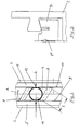
- the prior art and the invention comprise profile strips (2) which are assembled at right angles to a frame of a box structure (1) by means of angled corner connecting pieces (3) which represents the structure of a fire protection vehicle (not illustrated).
- Each corner connector (3) has a counterpart (4) in association with a clamp with an associated profile strip (2), the corner connector (3) and counterpart (4) being tightened by a screw connection (not shown) to generate a clamping force (F) can.
- the clamping force (F) acts on two inner longitudinal guides (5, 6) lying opposite one another, which are designed in one piece with the associated profiled strip (2) in a web-like manner.
- the longitudinal guides are dovetail-shaped with a corresponding counter-configuration of the engagement surfaces (7, 8) of the corner connector (3) or counterpart (4), while according to the invention the longitudinal guides ( 5,6) are convex in cross-section and, in particular in the area of the engagement surfaces (7,8) of the corner connector (3) or counterpart (4), are circular with the radius (r).
- a tightening torque on the screw, not shown, between the corner connector (3) and the counterpart (4) creates a surface load when the counterpart (4) is not elastically deformed on the engagement surfaces (7, 8), which is caused by multiple arrows in both the invention and the prior art is shown in Fig. 1.
- the essentially U-shaped profile strip (2) has flattened portions in the form of flat end faces (9 and 10) at the innermost point of the web-like longitudinal guides (5, 6) parallel to the legs of the "U".
- a counterpart according to the invention (4) according to FIG. 1, left, and FIG. 2 comprises a circular integrated collar (11) between the longitudinal guides (5, 6), onto which a clamping ring (12) in the form of a plastic rosette is attached in a fixed connection ,
- the outer diameter of the clamping ring (12) being accommodated in a displaceable press fit between the end faces (9, 10) of the longitudinal guides (5, 6), so that a counterpart (4) received in the longitudinal recess of the U-shaped profile strip (2) both in the profile bar and can be rotated according to the arrow of FIG. 2 about its vertical axis if the corner connector (3) is not connected to the counterpart (4) by screw.
- the counterparts (4) required in each case in the position illustrated in FIG.
- each counterpart (4) with the exception of the clamping ring (12), is narrower in width (b) than the distance between the end faces (9 and 10) of the longitudinal guides (5 , 6). Nevertheless, the effective length (1) of the engagement surfaces (8) of the counterpart (4) is greater than the width (b) of the counterpart itself, since they are located in an opposing oblique arrangement for transverse extension of the profile bar (2), as shown in Fig. 2 is illustrated.
- the two opposite engagement surfaces (8) have a concave curvature with the radius of curvature (r) in their oblique extension according to FIG. 2, as can be seen in FIG. 1.
- a clamp connection is established in that the counterpart (4) according to FIG. 2 is rotated in the direction of arrow (A) until the oblique engagement surfaces (8) are aligned with the longitudinal guides (5, 6) of the profile strips (2).
- the screw is tightened, all of the concave engagement surfaces (7, 8) of the corner connectors (3) and counterparts (4) according to the invention come into positive engagement.
- Minor misalignments of the counterpart (4) are automatically aligned when the screw is tightened, with the engagement surfaces (7, 8) on the longitudinal guides (5, 6) being given an exact form fit when the screw is tightened to the maximum.
- Possible scattering of the tightening torque of the screw during manufacture or stress peaks during use on the profile frame skeleton basically causes a slight elastic deflection on the counterpart (4).
- the clamping connection is constructed like a ball joint and the tensioning screw runs centrally, according to the invention the maximum surface pressure according to FIG. 1, left, is continuously maintained at the maximum tightening torque, while according to the prior art the surface pressure on the longitudinal guides is reduced to a linear load, as is shown in FIG. 3 is shown.
- the power transmission at the clamping point is therefore kept large according to the invention in every load case, while it is severely impaired according to the prior art.
Landscapes
- Engineering & Computer Science (AREA)
- Mechanical Engineering (AREA)
- General Engineering & Computer Science (AREA)
- Emergency Management (AREA)
- Health & Medical Sciences (AREA)
- Business, Economics & Management (AREA)
- Public Health (AREA)
- Chemical & Material Sciences (AREA)
- Combustion & Propulsion (AREA)
- Transportation (AREA)
- Clamps And Clips (AREA)
- Ladders (AREA)
- Building Environments (AREA)
- Fire-Extinguishing By Fire Departments, And Fire-Extinguishing Equipment And Control Thereof (AREA)
- Connection Of Plates (AREA)
Priority Applications (1)
| Application Number | Priority Date | Filing Date | Title |
|---|---|---|---|
| AT87114639T ATE67972T1 (de) | 1986-10-15 | 1987-10-07 | Kastenkonstruktion, insbesondere fuer nutzfahrzeuge wie beispielsweise brandschutzfahrzeuge. |
Applications Claiming Priority (2)
| Application Number | Priority Date | Filing Date | Title |
|---|---|---|---|
| DE3635039 | 1986-10-15 | ||
| DE19863635039 DE3635039A1 (de) | 1986-10-15 | 1986-10-15 | Kastenkonstruktion, insbesondere fuer nutzfahrzeuge wie beispielsweise brandschutzfahrzeuge |
Publications (3)
| Publication Number | Publication Date |
|---|---|
| EP0264058A2 true EP0264058A2 (fr) | 1988-04-20 |
| EP0264058A3 EP0264058A3 (en) | 1989-04-12 |
| EP0264058B1 EP0264058B1 (fr) | 1991-10-02 |
Family
ID=6311739
Family Applications (1)
| Application Number | Title | Priority Date | Filing Date |
|---|---|---|---|
| EP87114639A Expired - Lifetime EP0264058B1 (fr) | 1986-10-15 | 1987-10-07 | Construction de caisse, en particulier pour véhicule utilitaire, par exemple véhicule de lutte contre l'incendie |
Country Status (3)
| Country | Link |
|---|---|
| EP (1) | EP0264058B1 (fr) |
| AT (1) | ATE67972T1 (fr) |
| DE (2) | DE3635039A1 (fr) |
Cited By (1)
| Publication number | Priority date | Publication date | Assignee | Title |
|---|---|---|---|---|
| DE19831368A1 (de) * | 1998-07-13 | 2000-01-20 | Man Nutzfahrzeuge Ag | Vorrichtung zum Einspannen eines Halterohres für Nutzfahrzeuge |
Family Cites Families (3)
| Publication number | Priority date | Publication date | Assignee | Title |
|---|---|---|---|---|
| US3296759A (en) * | 1964-12-07 | 1967-01-10 | Pavlecka John | Interlocked hollow panel structure |
| DE1924009C3 (de) * | 1969-05-10 | 1974-09-26 | Staufen Fahrzeugwerke Eislingen R. Rayer Kg, 7332 Eislingen | Profilstab zum Zusammensetzen von ebenen Bauteilen von Fahrzeugaufbauten |
| GB1488083A (en) * | 1975-01-14 | 1977-10-05 | Nexus Mfg Ltd | Mechanical connections between adjacent members |
-
1986
- 1986-10-15 DE DE19863635039 patent/DE3635039A1/de not_active Withdrawn
-
1987
- 1987-10-07 EP EP87114639A patent/EP0264058B1/fr not_active Expired - Lifetime
- 1987-10-07 AT AT87114639T patent/ATE67972T1/de not_active IP Right Cessation
- 1987-10-07 DE DE8787114639T patent/DE3773460D1/de not_active Expired - Lifetime
Cited By (2)
| Publication number | Priority date | Publication date | Assignee | Title |
|---|---|---|---|---|
| DE19831368A1 (de) * | 1998-07-13 | 2000-01-20 | Man Nutzfahrzeuge Ag | Vorrichtung zum Einspannen eines Halterohres für Nutzfahrzeuge |
| DE19831368B4 (de) * | 1998-07-13 | 2004-04-08 | Man Nutzfahrzeuge Ag | Vorrichtung zum Einspannen eines Halterohres für Nutzfahrzeuge |
Also Published As
| Publication number | Publication date |
|---|---|
| EP0264058B1 (fr) | 1991-10-02 |
| ATE67972T1 (de) | 1991-10-15 |
| DE3635039A1 (de) | 1988-04-21 |
| DE3773460D1 (de) | 1991-11-07 |
| EP0264058A3 (en) | 1989-04-12 |
Similar Documents
| Publication | Publication Date | Title |
|---|---|---|
| EP0528213B1 (fr) | Elément de ferrure fixé par serrage dans une gorge profilée ayant au moins une contre-dépouille | |
| EP0445591A1 (fr) | Dispositif d'accouplement pour une colonne de direction d'un véhicule automobile avec la queue de l'arbre d'un mécanisme de direction | |
| DE19855928A1 (de) | Verbindung zweier Profilstäbe | |
| EP0830262B1 (fr) | Dispositif de recouvrement du joint de voie entre le disque rotatif d'une articulation tournante et le soufflet d'intercirculation ou un soufflet d'ondulation d'un vehicule articule | |
| EP1709990A2 (fr) | Dispositif pour fixer une électrode dans la poche du stimulateur cardiaque | |
| DE19958734B4 (de) | Sturzsicherungssystem und Trolley zur Anwendung in einem solchen System | |
| EP0264058B1 (fr) | Construction de caisse, en particulier pour véhicule utilitaire, par exemple véhicule de lutte contre l'incendie | |
| DE69118554T2 (de) | Verbindungsvorrichtung | |
| EP2347138B1 (fr) | Dispositif pour raccorder des tubes profilés | |
| DE4110185C1 (fr) | ||
| EP0226654A1 (fr) | Connecteur pour tubes et pour profilés creux tubulaires | |
| EP3347618A1 (fr) | Connecteur | |
| DE3536833A1 (de) | Kupplung zur spielfreien uebertragung rotatorischer bewegungen, insbesondere fuer praezisionsdrehpotentiometer, und verfahren zu ihrer herstellung | |
| DE3837444C1 (en) | Device for mutual clamping of two objects | |
| DE202021101970U1 (de) | Profilverbund | |
| DE2653376A1 (de) | Verbindungsvorrichtung fuer treibstangenbeschlaege von fenstern, tueren o.dgl. | |
| DE3444235C2 (fr) | ||
| DE102019219684B4 (de) | Antriebsanordnung | |
| DE3127758C2 (de) | Vorrichtung zur Verbindung von mit Flanschen versehenen Kunststoffrohren | |
| DE3504978A1 (de) | Spannmuffe | |
| DE69613091T2 (de) | Ein System von Profilelementen und Einsatzsteuerelementen zur Verwendung in diesem System | |
| DE19957640C2 (de) | Verbindungsvorrichtung | |
| DE2236702A1 (de) | Klemmvorrichtung zum befestigen von kabeln oder dergleichen an anderen bauteilen | |
| DE8803178U1 (de) | Verbindungsklemme für mehrere Schläuche, insbesondere für autogene Schweißapparate | |
| CH699953A1 (de) | Verbindungselement zum Verbinden von zwei Profilstücken. |
Legal Events
| Date | Code | Title | Description |
|---|---|---|---|
| PUAI | Public reference made under article 153(3) epc to a published international application that has entered the european phase |
Free format text: ORIGINAL CODE: 0009012 |
|
| AK | Designated contracting states |
Kind code of ref document: A2 Designated state(s): AT CH DE FR GB LI NL |
|
| PUAL | Search report despatched |
Free format text: ORIGINAL CODE: 0009013 |
|
| AK | Designated contracting states |
Kind code of ref document: A3 Designated state(s): AT CH DE FR GB LI NL |
|
| 17P | Request for examination filed |
Effective date: 19890915 |
|
| 17Q | First examination report despatched |
Effective date: 19910318 |
|
| GRAA | (expected) grant |
Free format text: ORIGINAL CODE: 0009210 |
|
| AK | Designated contracting states |
Kind code of ref document: B1 Designated state(s): AT CH DE FR GB LI NL |
|
| REF | Corresponds to: |
Ref document number: 67972 Country of ref document: AT Date of ref document: 19911015 Kind code of ref document: T |
|
| ET | Fr: translation filed | ||
| REF | Corresponds to: |
Ref document number: 3773460 Country of ref document: DE Date of ref document: 19911107 |
|
| GBT | Gb: translation of ep patent filed (gb section 77(6)(a)/1977) | ||
| PLBE | No opposition filed within time limit |
Free format text: ORIGINAL CODE: 0009261 |
|
| STAA | Information on the status of an ep patent application or granted ep patent |
Free format text: STATUS: NO OPPOSITION FILED WITHIN TIME LIMIT |
|
| 26N | No opposition filed | ||
| REG | Reference to a national code |
Ref country code: GB Ref legal event code: IF02 |
|
| PGFP | Annual fee paid to national office [announced via postgrant information from national office to epo] |
Ref country code: GB Payment date: 20031016 Year of fee payment: 17 Ref country code: FR Payment date: 20031016 Year of fee payment: 17 Ref country code: CH Payment date: 20031016 Year of fee payment: 17 |
|
| PGFP | Annual fee paid to national office [announced via postgrant information from national office to epo] |
Ref country code: NL Payment date: 20031021 Year of fee payment: 17 |
|
| PGFP | Annual fee paid to national office [announced via postgrant information from national office to epo] |
Ref country code: AT Payment date: 20031028 Year of fee payment: 17 |
|
| PGFP | Annual fee paid to national office [announced via postgrant information from national office to epo] |
Ref country code: DE Payment date: 20031127 Year of fee payment: 17 |
|
| PG25 | Lapsed in a contracting state [announced via postgrant information from national office to epo] |
Ref country code: GB Free format text: LAPSE BECAUSE OF NON-PAYMENT OF DUE FEES Effective date: 20041007 Ref country code: AT Free format text: LAPSE BECAUSE OF NON-PAYMENT OF DUE FEES Effective date: 20041007 |
|
| PG25 | Lapsed in a contracting state [announced via postgrant information from national office to epo] |
Ref country code: CH Free format text: LAPSE BECAUSE OF NON-PAYMENT OF DUE FEES Effective date: 20041031 Ref country code: LI Free format text: LAPSE BECAUSE OF NON-PAYMENT OF DUE FEES Effective date: 20041031 |
|
| PG25 | Lapsed in a contracting state [announced via postgrant information from national office to epo] |
Ref country code: NL Free format text: LAPSE BECAUSE OF NON-PAYMENT OF DUE FEES Effective date: 20050501 |
|
| PG25 | Lapsed in a contracting state [announced via postgrant information from national office to epo] |
Ref country code: DE Free format text: LAPSE BECAUSE OF NON-PAYMENT OF DUE FEES Effective date: 20050503 |
|
| GBPC | Gb: european patent ceased through non-payment of renewal fee |
Effective date: 20041007 |
|
| REG | Reference to a national code |
Ref country code: CH Ref legal event code: PL |
|
| PG25 | Lapsed in a contracting state [announced via postgrant information from national office to epo] |
Ref country code: FR Free format text: LAPSE BECAUSE OF NON-PAYMENT OF DUE FEES Effective date: 20050630 |
|
| NLV4 | Nl: lapsed or anulled due to non-payment of the annual fee |
Effective date: 20050501 |
|
| REG | Reference to a national code |
Ref country code: FR Ref legal event code: ST |