EP0264064B1 - Wortsynchronisator - Google Patents
Wortsynchronisator Download PDFInfo
- Publication number
- EP0264064B1 EP0264064B1 EP87114691A EP87114691A EP0264064B1 EP 0264064 B1 EP0264064 B1 EP 0264064B1 EP 87114691 A EP87114691 A EP 87114691A EP 87114691 A EP87114691 A EP 87114691A EP 0264064 B1 EP0264064 B1 EP 0264064B1
- Authority
- EP
- European Patent Office
- Prior art keywords
- syndrome
- pulse
- bit
- response
- hunting
- Prior art date
- Legal status (The legal status is an assumption and is not a legal conclusion. Google has not performed a legal analysis and makes no representation as to the accuracy of the status listed.)
- Expired - Lifetime
Links
- 208000011580 syndromic disease Diseases 0.000 claims description 88
- 230000003111 delayed effect Effects 0.000 claims description 9
- 238000000034 method Methods 0.000 claims 2
- 238000010586 diagram Methods 0.000 description 3
- 230000002159 abnormal effect Effects 0.000 description 1
- 125000004122 cyclic group Chemical group 0.000 description 1
- 238000012986 modification Methods 0.000 description 1
- 230000004048 modification Effects 0.000 description 1
- 230000001360 synchronised effect Effects 0.000 description 1
Images


Classifications
-
- H—ELECTRICITY
- H03—ELECTRONIC CIRCUITRY
- H03M—CODING; DECODING; CODE CONVERSION IN GENERAL
- H03M13/00—Coding, decoding or code conversion, for error detection or error correction; Coding theory basic assumptions; Coding bounds; Error probability evaluation methods; Channel models; Simulation or testing of codes
- H03M13/33—Synchronisation based on error coding or decoding
Definitions
- the present invention relates to a word synchronizer for synchronizing a syndrome calculator to the word timing of a data bit stream.
- a known word synchronizer comprises a syndrome calculator and a single-stage shift register.
- the syndrome calculator is initialized at every N bits of an incoming N-bit word in the absence of a syndrome and additionally initialized at l bit interval delayed after the every N-bit initialization in the presence of a syndrome in search of the beginning of a valid data word.
- the word synchronizer is allowed a short interval of time to extract a syndrome from the syndrome calculator and store it for a subsequent word interval. Therefore, it must be constructed of components capable of operating at high speeds.
- JP-A-59-230344 discloses a frame synchronizing circuit. Said document teaches the provision of a comparator which compares data at a location having a data string in synchronization with a clock with a synchronizing signal. When lack of synchronization is detected, a hunting mode is entered, wherein a hunting pulse initiates the shifting of the count state of a frame count number circuit by ⁇ -bits, whereby ⁇ is mutually prime to the frame bit number.
- this object is obtained by initializing a syndrome calculator at every N bits of an N-bit word in the absence of a syndrome and initializing it at every N bits and at M-bit interval delayed after the every N-bit initialization in the presence of a syndrome, wherein the integers N and M are relatively prime to each other.
- a word synchronizer of the present invention is connected to a demodulator, not shown, to receive through input line 10 a series of N-bit words which have been encoded with an error correcting code and apply it to a syndrome calculator 11 of a known design.
- syndrome calculator 11 When an error is detected in the received data bit stream or when the word timing of the syndrome calculator 11 is out of word sync with the input bit stream, syndrome calculator 11 generates a parallel output which is latched into a syndrome latch 12.
- the output of the word synchronizer is taken from the syndrome latch 12 through an output bus 12a to an error corrector 20 which corrects error bits in the incoming data bit stream supplied on line 22 with the syndrome and supplies error-corrected data bit stream to an output line 21.
- syndrome latch 12 During the presence of a syndrome, syndrome latch 12 further generates a syndrome presence signal on line 12b to a word synchronization detector 13 and an AND gate 16 to which the output of word sync detector 13 is also applied.
- a clock input which is synchronized with the bit timing of the data bit stream, is also supplied from the demodulator through an input terminal 18 to syndrome calculator 11, syndrome latch 12 and word sync detector 13.
- a timing circuit 14 is provided to count the clock input and supply a hunting pulse 14a for every N bits to the data input of an M-stage shift register 15.
- Shift register 15 produces a copy of the hunting pulse 14a and generates an output when that copy has shifted along its M-stages in response to the clock input and supplies it to AND gate 16 as a delayed hunting pulse 15a to allow the syndrome calculator 11 to perform syndrome calculation in search of the beginning of a data word.
- the hunting pulse 14a from timing circuit 14 is also applied to an OR gate 17 to which the output of AND gate 16 is also applied.
- Or gate 17 supplies its output as an initializing pulse 17a to the reset inputs of syndrome calculator 11, syndrome latch 12 and word sync detector 13.
- syndrome calculator 11 comprises a syndrome calculation logic 30 and a timing circuit 31 which counts the clock input in response to the initializing pulse 17a and supplies appropriately delayed reset pulses to various stages of the calculation logic.
- Syndrome latch 12 is constructed of a latch 40, a timing circuit 41 and an OR gate 42.
- Timing circuit 41 is reset by the initializing pulse 17a to count the clock input and supply a load timing pulse to a load enable input of the latch 40 when the count attains a value C which is appropriately determined anywhere between unity and the integer M of the M-stage shift register 15.
- a syndrome generated in the syndrome calculation logic 30 is latched into the latch 40 in response to the load timing pulse and stored therein until it is reset by the initializing pulse 17a.
- the syndrome is stored in the latch 40 for a period equal to the length of a data word.
- the outputs of latch 40 are connected to OR gate 42 to produce a logical-one output whenever a syndrome is generated.
- OR gate 42 The logical-one output of OR gate 42 is applied as a syndrome presence signal 12b to the word sync detector 13 and AND gate 16.
- Word sync detector 13 generates a logical-one output as an indication of out-of-word sync condition when it counts syndrome-generating K words before it counts L words that generate no syndrome and generates a logical-zero output as an indication of in-word-sync condition when it counts L words that generate no syndrome before it counts syndrome-generating K words.
- the integer N of the word length and the integer M of the shift register stages are "relatively prime" to each other; namely, the integers N and M have no common divisor except for unity. If the input data word is of 84-bit length including error control redundant bits, one suitable value for the integer M is 13.
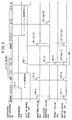
- Fig. 3 The operation of the circuit of Fig. 1 will now be described with reference to Fig. 3. Assume that the input data word is 84-bit long and the shift register 15 has 13 stages. In addition, the timing circuit 42 of syndrome latch 12 enables the latch 40 at the count of 4 bits from the receipt of an initializing pulse 17a from OR gate 17. It is assumed that the word synchronizer is initially word-synchronized so that outputs 12b and 13a are initially low, but for some reasons timing slips have occurred between the word timing of the incoming data and the word timing of the syndrome calculator, resulting in the generation of a syndrome in the syndrome calculator 11.
- a hunting pulse 14-1 is generated at the count of 84 clock pulses by the timing circuit 14 regardless of whether it coincides with the end of an incoming word or not. Hunting pulse 14-1 is applied to the 13-stage shift register 15 and further applied through OR gate 17 as an initializing pulse 17-1 to the syndrome calculator 11 and syndrome latch 12.
- the syndrome generated in the syndrome calculator 11 is latched into the syndrome latch 12 at the fourth bit from the receipt of the initializing pulse 17-1. Therefore, a syndrome presence signal 12-1 is applied to the word sync detector 13 and AND gate 16. If the syndrome continues for a perid greater than the length of K input data words, the word sync detector 13 generates a logical-one output (out-of-word sync) 13-1 at the fourth bit of the K-th word. During this K-word interval, hunting pulses 14-2 to 14-k and initializing pulses 17-2 to 17-k are generated, with the resultant generation of delayed hunting pulses 15-1 through 15-k.
- the hunting pulse 15-k is passed through the AND gate and applied as a reset pulse 16-1 to timing circuit 14 and OR gate 17, producing an initializing pulse 17-(k+1). Therefore, at the 13th of the K-th word, the timing circuit 14 is reset and the syndrome calculator 11 and syndrome latch 12 are initialized. At the end of the K-th word, the timing circuit 14 generates a hunting pulse 14-(k+1), causing the OR gate 17 to supply an initializing pulse 17-(k+2).
- a delayed hunting pulse 15-(k+1), not shown will be generated at the 13-th bit of the (K+1)-th word in response to the hunting pulse 14-(k+1) in a manner similar to the pulse event that occurred at the 13-th bit of the K-th word. Therefore, pulse events marked 19 in Fig. 3 will be recyclically generated as long as the out-of-word sync condition continues.
- syndrome calculator 11 treats the first bit of an incoming data bit stream as if it were the beginning of a valid data word.
- the time at which the syndrome calculator 11 is initialized is shifted from one bit to another upon calculation of a string of data bits for the length of a word so that the word synchronizer hunts for all the bits of N-bit words in search of their word timing as long as the out-of-word sync condition exists.
- the syndrome latch 12 is allowed to extract the syndrome within the period of 13 bits as compared to the prior art word synchronizer in which the period of only one bit is allowed to extract a syndrome. This relaxes the operating requirements of the syndrome calculator and syndrome latch and allows a greater freedom of choice for selecting a desired error correcting code.
- the number of stages of the shift register 15 may be set equal to a value greater than the integer N.
Landscapes
- Physics & Mathematics (AREA)
- Probability & Statistics with Applications (AREA)
- Engineering & Computer Science (AREA)
- Theoretical Computer Science (AREA)
- Synchronisation In Digital Transmission Systems (AREA)
- Error Detection And Correction (AREA)
- Detection And Prevention Of Errors In Transmission (AREA)
Claims (3)
- Verfahren zum Herstellen von Synchronisation zwischen einem Datenbitstrom von mit einem Fehlerkorrekturcode codierten N-Bit-Wörtern und der Zeitmessung der Fehlersyndromberechnung mit den Schritten:a) Erhöhen eines Zählerstands als Antwort auf jedes Bit der N-Bit-Wörter und Erzeugen eines Selbstregelungsimpulses für jeden Zählerstand der N Bits und eines Leistungszeitimpulses bei jedem Zählerstand von C Bits, wobei die ganze Zahl C größer als eins ist;b) Durchführen der Fehlersyndromberechnung auf den N-Bit-Wörtern als Antwort auf den Selbstregelungsimpuls und daraus Ableiten eines Fehlersyndroms;c) Speichern des Fehlersyndroms und Erzeugen eines ersten Freigabesignals als Antwort auf den Leistungszeitimpuls;d) Zählen von Wörtern, die das Fehlersyndrom erzeugen, und Erzeugen eines zweiten Freigabesignals, wenn der Zählerstand eine Gegenwortsynchronisation anzeigt; unde) Verzögern des Selbstregelungsimpulses um eine Zeitdauer von M Bits, wenn das erste und zweite Freigabesignal gleichzeitig vorhanden sind, und Bewirken des Schrittes (b), um als Antwort auf den verzögerten Selbstregelungsimpuls zusätzlich die Berechnung durchzuführen, wobei die ganze Zahl M größer als die ganze Zahl C ist, und die ganzen Zahlen M und N relativ zueinander Primzahlen sind.
- Wortsynchronisator für das Verfahren nach Anspruch 1, der einen Datenbitstrom von mit einem Fehlerkorrekturcode codierten N-Bit-Wörtern empfangen kann, mit:
Zählereinrichtungen (14, 41) zum Erhöhen eines Zählerstands als Antwort auf jedes Bit der N-Bit-Wörter und Erzeugen eines Selbstregelungsimpulses für jeden Zählerstand von N Bits und eines Leistungszeitimpulses für jeden Zählerstand von C Bits, wobei die ganze Zahl C größer als eins ist;
einer Fehlersyndromberechnungseinrichtung (11), um als Antwort auf den Selbstregelungsimpuls die Fehlersyndromberechnung auf den N-Bit-Wörtern durchzuführen und daraus ein Fehlersyndrom abzuleiten;
einer Fehlersyndromsperreinrichtung (40), um das Fehlersyndrom zu speichern und ein erstes Freigabesignal als Antwort auf den Leistungszeitimpuls zu erzeugen;
einer mit der Fehlersyndromsperreinrichtung (40) verbundenen Wortsynchronisationsnachweiseinrichtung (13), um die Wörter, die das Fehlersyndrom erzeugen, zu zählen und ein zweites Freigabesignal zu erzeugen, wenn der Zählerstand eine Gegenwortsynchronisation anzeigt; und
Schieberegistereinrichtungen (15, 16) mit M Stufen, um den Selbstregelungsimpuls um eine Zeitdauer von M Bits zu verzögern, wenn das erste und zweite Freigabesignal gleichzeitig vorhanden sind, und um zu bewirken, daß als Antwort auf den verzögerten Selbstregelungsimpuls die Fehlersyndromberechnungseinrichtung (40) zusätzlich die Berechnung durchführt, wobei die ganze Zahl M größer als die ganze Zahl C ist, und die ganzen Zahlen M und N relativ zueinander Primzahlen sind. - Wortsynchronisator nach Anspruch 2, wobei die Zählereinrichtungen (14, 41) einen ersten rücksetzbaren Zähler (14), um jedes Bit der N-Bit-Wörter zu zählen und einen Selbstregelungsimpuls für jeden Zählerstand der N Bits zu erzeugen, und einen zweiten rücksetzbaren Zähler (41) aufweisen, der so angeordnet ist, daß er als Antwort auf den Selbstregelungsimpuls und einen ihm zugeführten Initialisierungsimpuls initialisiert wird, um jedes Bit der N-Bit-Wörter zu zählen und einen Leistungszeitimpuls bei jedem Zählerstand von C Bits zu erzeugen, wobei die ganze Zahl C größer als eins und kleiner als die ganze Zahl M ist,
wobei die Schieberegistereinrichtungen (15, 16) ein Schieberegister (15) mit M Stufen, um den Selbstregelungsimpuls zu empfangen und ihn um eine Zeitdauer von M Bits zu verzögern, und ein Gatter (16) aufweisen, um als Antwort auf den verzögerten Selbstregelungsimpuls ein Ausgangssignal zu erzeugen, wenn es durch das erste und zweite Freigabesignal freigegeben ist, und um das Ausgangssignal des Gatters zu dem zweiten rücksetzbaren Zähler (41) als den Initialisierungsimpuls zuzuführen, und
wobei die Fehlersyndromberechnungseinrichtung (11) einen rücksetzbaren Fehlersyndromrechner (30) umfaßt, der so angeordnet ist, daß er als Antwort auf den Selbstregelungsimpuls und ein Ausgangssignal des Gatters (16) initialisiert wird, um auf den N-Bit-Wörtern eine Berechnung durchzuführen und daraus ein Fehlersyndrom abzuleiten.
Applications Claiming Priority (2)
| Application Number | Priority Date | Filing Date | Title |
|---|---|---|---|
| JP61240714A JPH071885B2 (ja) | 1986-10-09 | 1986-10-09 | ワ−ド同期器 |
| JP240714/86 | 1986-10-09 |
Publications (3)
| Publication Number | Publication Date |
|---|---|
| EP0264064A2 EP0264064A2 (de) | 1988-04-20 |
| EP0264064A3 EP0264064A3 (de) | 1991-04-03 |
| EP0264064B1 true EP0264064B1 (de) | 1994-03-23 |
Family
ID=17063613
Family Applications (1)
| Application Number | Title | Priority Date | Filing Date |
|---|---|---|---|
| EP87114691A Expired - Lifetime EP0264064B1 (de) | 1986-10-09 | 1987-10-08 | Wortsynchronisator |
Country Status (5)
| Country | Link |
|---|---|
| US (1) | US4870646A (de) |
| EP (1) | EP0264064B1 (de) |
| JP (1) | JPH071885B2 (de) |
| CA (1) | CA1289260C (de) |
| DE (1) | DE3789415T2 (de) |
Families Citing this family (3)
| Publication number | Priority date | Publication date | Assignee | Title |
|---|---|---|---|---|
| JP2597872B2 (ja) * | 1988-02-13 | 1997-04-09 | 日本電信電話株式会社 | ブロック同期方式 |
| US5280484A (en) * | 1989-07-08 | 1994-01-18 | Alcatel N.V. | Time-division multiplex communication system with a synchronizing circuit at the receiving end which responds to the coding of words inserted in the transmitted information |
| GB9213273D0 (en) * | 1992-06-23 | 1992-08-05 | Digital Equipment Int | Efficient atm cell synchronization |
Family Cites Families (5)
| Publication number | Priority date | Publication date | Assignee | Title |
|---|---|---|---|---|
| US3668632A (en) * | 1969-02-13 | 1972-06-06 | Ibm | Fast decode character error detection and correction system |
| IT1006135B (it) * | 1973-12-27 | 1976-09-30 | Sits Soc It Telecom Siemens | Disposizioni circuitale per la cor rezione dell errore di scorrimento nei sistemi di trasmissione dati utilizzanti codici ciclici |
| US4404676A (en) * | 1981-03-30 | 1983-09-13 | Pioneer Electric Corporation | Partitioning method and apparatus using data-dependent boundary-marking code words |
| JPS5817745A (ja) * | 1981-07-17 | 1983-02-02 | Victor Co Of Japan Ltd | 同期検出方式 |
| US4747105A (en) * | 1986-09-03 | 1988-05-24 | Motorola, Inc. | Linear feedback sequence detection with error correction |
-
1986
- 1986-10-09 JP JP61240714A patent/JPH071885B2/ja not_active Expired - Lifetime
-
1987
- 1987-10-08 CA CA000548846A patent/CA1289260C/en not_active Expired - Lifetime
- 1987-10-08 DE DE3789415T patent/DE3789415T2/de not_active Expired - Fee Related
- 1987-10-08 EP EP87114691A patent/EP0264064B1/de not_active Expired - Lifetime
- 1987-10-09 US US07/106,292 patent/US4870646A/en not_active Expired - Lifetime
Also Published As
| Publication number | Publication date |
|---|---|
| JPH071885B2 (ja) | 1995-01-11 |
| EP0264064A3 (de) | 1991-04-03 |
| DE3789415T2 (de) | 1994-08-18 |
| DE3789415D1 (de) | 1994-04-28 |
| US4870646A (en) | 1989-09-26 |
| EP0264064A2 (de) | 1988-04-20 |
| JPS6395747A (ja) | 1988-04-26 |
| CA1289260C (en) | 1991-09-17 |
Similar Documents
| Publication | Publication Date | Title |
|---|---|---|
| JP2732759B2 (ja) | フレーム同期制御方式 | |
| US4059825A (en) | Burst/slip correction decoder and method | |
| US4506372A (en) | Method and apparatus for recognizing in a receiver the start of a telegram signal consisting of a bit impulse sequence | |
| JP2578334B2 (ja) | デイジタル伝送方式 | |
| JP3049296B2 (ja) | シーケンス同期方法及び装置 | |
| JP3130344B2 (ja) | データの並直列変換装置及び直並列変換装置、並びに直列データのディジタル伝送システム | |
| US5428627A (en) | Method and apparatus for initializing an ECC circuit | |
| JP3046988B2 (ja) | データストリームのフレーム同期検出方法及び装置 | |
| US3466601A (en) | Automatic synchronization recovery techniques for cyclic codes | |
| EP0600380A2 (de) | Verfahren und Einrichtung zur Feststellung und Korrektur von Fehlern im Kopffeld von ATM-Zellen | |
| US4943985A (en) | Frame synchronization device for a synchronous digital bit stream divided into blocks by means of a block code and structured in frames | |
| US4032886A (en) | Concatenation technique for burst-error correction and synchronization | |
| JPH0778774B2 (ja) | 短待ち時間データ回復装置及びメッセージデータの同期化方法 | |
| KR950009690B1 (ko) | 순환 여유검사(crc) 동기 장치 | |
| EP0264064B1 (de) | Wortsynchronisator | |
| US4680765A (en) | Autosync circuit for error correcting block decoders | |
| US5651015A (en) | Apparatus and method for synchronization and error detection of received digital data bursts in a TDM/TDMA system | |
| JP2710427B2 (ja) | データブロック信号伝送方法及びその装置 | |
| US5265105A (en) | Decoding circuit for inhibiting error propagation | |
| JP2967748B2 (ja) | Atmセル同期回路 | |
| JP3829702B2 (ja) | フレーム同期装置及び方法 | |
| JP2944319B2 (ja) | 並列展開型フレーム同期方式 | |
| JPS60235549A (ja) | nB1C符号信号のCビツト同期方式 | |
| JP3110387B2 (ja) | マルチフレーム同期検出装置 | |
| RU2272360C1 (ru) | Устройство для передачи данных |
Legal Events
| Date | Code | Title | Description |
|---|---|---|---|
| PUAI | Public reference made under article 153(3) epc to a published international application that has entered the european phase |
Free format text: ORIGINAL CODE: 0009012 |
|
| 17P | Request for examination filed |
Effective date: 19871008 |
|
| AK | Designated contracting states |
Kind code of ref document: A2 Designated state(s): DE IT SE |
|
| PUAL | Search report despatched |
Free format text: ORIGINAL CODE: 0009013 |
|
| AK | Designated contracting states |
Kind code of ref document: A3 Designated state(s): DE IT SE |
|
| 17Q | First examination report despatched |
Effective date: 19920701 |
|
| GRAA | (expected) grant |
Free format text: ORIGINAL CODE: 0009210 |
|
| AK | Designated contracting states |
Kind code of ref document: B1 Designated state(s): DE IT SE |
|
| REF | Corresponds to: |
Ref document number: 3789415 Country of ref document: DE Date of ref document: 19940428 |
|
| ITF | It: translation for a ep patent filed | ||
| PLBE | No opposition filed within time limit |
Free format text: ORIGINAL CODE: 0009261 |
|
| STAA | Information on the status of an ep patent application or granted ep patent |
Free format text: STATUS: NO OPPOSITION FILED WITHIN TIME LIMIT |
|
| EAL | Se: european patent in force in sweden |
Ref document number: 87114691.6 |
|
| 26N | No opposition filed | ||
| PGFP | Annual fee paid to national office [announced via postgrant information from national office to epo] |
Ref country code: SE Payment date: 20021009 Year of fee payment: 16 |
|
| PGFP | Annual fee paid to national office [announced via postgrant information from national office to epo] |
Ref country code: DE Payment date: 20021011 Year of fee payment: 16 |
|
| PG25 | Lapsed in a contracting state [announced via postgrant information from national office to epo] |
Ref country code: SE Free format text: LAPSE BECAUSE OF NON-PAYMENT OF DUE FEES Effective date: 20031009 |
|
| PG25 | Lapsed in a contracting state [announced via postgrant information from national office to epo] |
Ref country code: DE Free format text: LAPSE BECAUSE OF NON-PAYMENT OF DUE FEES Effective date: 20040501 |
|
| EUG | Se: european patent has lapsed | ||
| PG25 | Lapsed in a contracting state [announced via postgrant information from national office to epo] |
Ref country code: IT Free format text: LAPSE BECAUSE OF NON-PAYMENT OF DUE FEES;WARNING: LAPSES OF ITALIAN PATENTS WITH EFFECTIVE DATE BEFORE 2007 MAY HAVE OCCURRED AT ANY TIME BEFORE 2007. THE CORRECT EFFECTIVE DATE MAY BE DIFFERENT FROM THE ONE RECORDED. Effective date: 20051008 |