EP0264084A2 - Table extensible by at least one leaf - Google Patents
Table extensible by at least one leaf Download PDFInfo
- Publication number
- EP0264084A2 EP0264084A2 EP87114812A EP87114812A EP0264084A2 EP 0264084 A2 EP0264084 A2 EP 0264084A2 EP 87114812 A EP87114812 A EP 87114812A EP 87114812 A EP87114812 A EP 87114812A EP 0264084 A2 EP0264084 A2 EP 0264084A2
- Authority
- EP
- European Patent Office
- Prior art keywords
- plate
- pull
- holding part
- table top
- holding
- Prior art date
- Legal status (The legal status is an assumption and is not a legal conclusion. Google has not performed a legal analysis and makes no representation as to the accuracy of the status listed.)
- Withdrawn
Links
Images



Classifications
-
- A—HUMAN NECESSITIES
- A47—FURNITURE; DOMESTIC ARTICLES OR APPLIANCES; COFFEE MILLS; SPICE MILLS; SUCTION CLEANERS IN GENERAL
- A47B—TABLES; DESKS; OFFICE FURNITURE; CABINETS; DRAWERS; GENERAL DETAILS OF FURNITURE
- A47B1/00—Extensible tables
- A47B1/04—Extensible tables with supplementary leaves or drop leaves arranged at the periphery
Definitions
- the present invention relates to a table with a table top that can be enlarged by at least one pull-out part.
- fittings are used for the pull-out parts, which enable the respective table to be transformed in the sense that the usable area of the table top is enlarged.
- the present invention is based on the object to create a table of the generic type, which is inexpensive to manufacture, easy to use and - if several pull-out parts are present - can also only be partially enlarged without problems.
- the pull-out part consists of a fitting insertable in a slot immediately below the table top insertable plate and a fixed to this plate, strip or disc-like holding part that the thickness of the plate and the holding part and the inside height of Slide-in compartments correspond to the thickness of the tabletop, that the holding part protrudes beyond an end edge of the tabletop and is limited in the area lying on the tabletop by an edge corresponding to the contour of the front edge of the tabletop protruding from the holding part, and that the outer edge of the tabletop delimiting the upper compartment of the tabletop has the same contour as the front edge of the plate or the correspondingly designed edge of the holding part.
- the possibility is created of converting a table as quickly as possible, and depending on the number of pull-out parts used, a considerable increase in the usable table area can be achieved.
- the table top is supplemented either by the surface that increases the usable area or the holding part, depending on the position in which the pull-out part is partially inserted into the slot.
- the plate of the pull-out part in the one inserted in the drawer so the holding part complements the table top
- the holding part if the holding part is pushed into the slot, the top of the pull-out part now complements the table top, with a clear increase in the usable table area being achieved at the same time.
- the table shown schematically in FIGS. 1 and 2 and provided overall with reference number 10 has a table top 11 which can be enlarged by means of two pull-out parts 12.
- Each pull-out part 12 consists of a plate 13 which considerably increases the usable table area and a holding part 14 fastened on this plate 13, which is strip-shaped in the exemplary embodiment according to FIGS. 1 and 2.
- FIG. 2 in particular makes it clear that the strip-shaped holding part 14 projects over an end edge 15 of the respective plate 13.
- the holding part 14 is delimited in its area lying on the plate 13 by an edge 16, the contour of which corresponds to that of the front edge 15 of the plate 13.
- FIG. 2 also makes clear, an insertion compartment 17 is provided immediately below the table top 11 for each pull-out part 12.
- the outer edge 18 of the table top 11 delimiting the respective insertion compartment 17 on the top side in turn has the same Contour course like the front edge 15 of the plate 13 or the correspondingly designed edge 16 of the holding part 14.
- the thickness of the plate 13 corresponds to the thickness of the holding part 14 and the thickness of the table top 11.
- the clear height of the slot 17 is matched to the thickness of the plate 13 and the holding part 14, which results in the following possible uses:
- the pull-out parts 12 are first pulled out of their slide-in compartments 17 and then inserted into the slide-in compartments 17 with their holding parts 14 in the position shown on the right-hand side of FIG.
- the plates 13 now increase the total usable table area, as can be easily seen from FIG.
- the thickness of the plates 13 corresponds to the thickness of the table top 11 and also due to the fact that the thickness of the holding parts 14 corresponds to the clear height of the compartments 17, it follows that the plates 13 by simply inserting the holding parts 14 are adequately securely fixed in the drawers 17 and lock on the top side in one plane with the table top 11.
- the last-mentioned advantage is also achieved if only one of the pull-out parts 12 is used, as shown in FIG. 2.
- the table 10 shown in Figures 3 and 4 differs from the embodiment of Figures 1 and 2 only in that it has an essentially square table top 11 and is provided with four pull-out parts 12, by means of which the usable table surface can be almost doubled.
- the pull-out parts 12 each consist of plates 13 and retaining parts 14 fastened thereon in the form of strips.
- Handling and function of the holding parts 12 corresponds to the exemplary embodiment according to FIGS. 1 and 2, to the description of which reference can be made in this respect.
- the table 10 shown in Figures 5 to 9 is equipped with an overall round table top 11.
- the table 10 is provided with a total of four pull-out parts 12 which, in the exemplary embodiment shown, make it possible to turn a round table surface into a square table surface, which is shown particularly clearly in FIG. 6.
- the pull-out parts each consist of a plate 13 and a holding part 14 connected to it, which can be described as disk-shaped and has a biconvex base surface, whereas the respective plate 13 has an approximately quarter-circular plan.
- Each disk-shaped holding part 14 stands over the plate 13 in front, specifically in the area of the end edge 15 that runs in this case in an arcuate manner.
- the edge 16 of the holding part 14 lying in the area lying on the plate 13 is designed to be correspondingly curved.
- the slide-in compartments 17 for receiving either the plates 13 or a part of the In the exemplary embodiment of the invention according to FIGS. 5 to 9, holding parts 14 are again delimited on the top in a circular arc, specifically by the outer edge of the table top 11 provided with the reference symbol 18.
- the table has the shape shown in FIG. 5.
- the holding parts 14 complement the table top 11 to its complete circular shape.
- the holding parts 14 engage with their regions which protrude beyond the end edge 15 of the plates 13 into the compartments 17.
- the front edge 15 of the respective plates 13 lies against the corresponding outer edges 18 of the table top 11 so that in turn a self-contained table surface is produced.
- pull-out parts 12 are used, as shown in FIG. 6, an approximately square table is created. However, it is also readily possible to use only one or two of the pull-out parts 12 with a smaller space requirement. This is also easily possible because a change in the use of the pull-out parts 12 Height of the usable table surface does not occur.
- the insertion compartment 17 is delimited by a support plate 19, which is provided with a coating 20 made of a soft and elastic material, preferably of flake felt.
- a coating 20 made of a soft and elastic material, preferably of flake felt.
- the corners of the quarter-circular plates 13 can of course be more or less rounded.
- both wood and plastic or other materials customary in furniture construction can be used.
- Material combinations can also be used, for example the pull-out parts 12 can be made of a different material than the table top 11.
Landscapes
- Tables And Desks Characterized By Structural Shape (AREA)
- Materials For Photolithography (AREA)
Abstract
Die Tischplatte (11) eines Tisches (10) ist mit mehreren Auszugteilen (12) versehen, die beschlagfrei in unterhalb der Tischplatte (11) angeordnete Einschubfächer (17) einschiebbar sind.The table top (11) of a table (10) is provided with a plurality of pull-out parts (12) which can be inserted without fittings into slots (17) arranged below the table top (11).
Diese Auszugteile (12) bestehen jeweils aus einer Platte (13) sowie einem darauf befestigten, leisten- oder scheibenartigen Halteteil (14), wobei ein wechselweises Einsetzen von Platte (13) und Halteteil (14) in die Einschubfächer möglich ist. Sämtliche Auszugteile (12) können jeweils unabhängig voneinander in ihre möglichen Gebrauchslagen gebracht werden. Innerhalb der nutzbaren Tischfläche ergibt sich hierbei keinerlei Höhenversatz. 
Description
Die vorliegende Erfindung betrifft einen Tisch mit einer durch mindestens ein Auszugteil vergrößerbaren Tischplatte.The present invention relates to a table with a table top that can be enlarged by at least one pull-out part.
Tische der vorerwähnten Art sind in verschiedenen Ausführungsformen bekannt.Tables of the aforementioned type are known in various embodiments.
Bei den vorbekannten Konstruktionen werden für die Auszugteile Beschläge verwendet, welche ein Verwandeln des jeweiligen Tisches in dem Sinne ermöglichen, daß die nutzbare Fläche der Tischplatte vergrößert wird.In the previously known constructions, fittings are used for the pull-out parts, which enable the respective table to be transformed in the sense that the usable area of the table top is enlarged.
Abgesehen davon, daß die Verwendung von Beschlägen einen derartigen Tisch prinzipiell verteuert, weisen die vorbekannten Konstruktionen auch noch den Nachteil auf, daß bei dem Wunsch nach vergrößerter Nutzfläche der Tischplatte eine vollständige Verwandlung des Tisches notwendig ist. Bei einer nur teilweisen Nutzung der Auszugteile liegen bei vorbekannten Tischen diese dann nicht in einer Höhe mit der Tischplatte im übrigen.In addition to the fact that the use of fittings makes such a table more expensive in principle, the previously known constructions also have the disadvantage that a complete transformation of the table is necessary if there is a need for an enlarged usable surface of the table top. If the pull-out parts are only partially used, they are not at the same height as the tabletop in the case of previously known tables.
Der vorliegenden Erfindung liegt die Aufgabe zugrunde, einen Tisch der gattungsgemäßen Art zu schaffen, der kostengünstig herstellbar, einfach bedienbar und - beim Vorhandensein mehrerer Auszugteile - auch problemlos nur teilweise vergrößerbar ist.The present invention is based on the object to create a table of the generic type, which is inexpensive to manufacture, easy to use and - if several pull-out parts are present - can also only be partially enlarged without problems.
Diese Aufgabe wird erfindungsgemäß dadurch gelöst, daß daß Auszugteil aus einer beschlagfrei in ein unmittelbar unterhalb der Tischplatte liegendes Einschubfach einschiebbaren Platte sowie einem auf dieser Platte befestigten, leisten- oder scheibenartigen Halteteil besteht, daß die Dicke der Platte und des Halteteiles und die lichte Höhe des Einschubfaches der Dicke der Tischplatte entsprechen, daß das Halteteil über eine Stirnkante der Platte hinaus vorsteht und in dem auf der Platte aufliegenden Bereich durch eine dem Konturenverlauf der vom Halteteil überragten Stirnkante der Platte entsprechenden Kante begrenzt ist und daß die das Einschubfach oberseitig begrenzende Außenkante der Tischplatte den gleichen Konturenverlauf aufweist, wie die Stirnkante der Platte bzw. die entsprechend gestaltete Kante des Halteteiles.This object is achieved in that the pull-out part consists of a fitting insertable in a slot immediately below the table top insertable plate and a fixed to this plate, strip or disc-like holding part that the thickness of the plate and the holding part and the inside height of Slide-in compartments correspond to the thickness of the tabletop, that the holding part protrudes beyond an end edge of the tabletop and is limited in the area lying on the tabletop by an edge corresponding to the contour of the front edge of the tabletop protruding from the holding part, and that the outer edge of the tabletop delimiting the upper compartment of the tabletop has the same contour as the front edge of the plate or the correspondingly designed edge of the holding part.
Durch eine derart einfache Konstruktion wird unter Verzicht jedweder Beschlagteile die Möglichkeit geschaffen, einen Tisch schnellstens zu verwandeln, wobei in Abhängigkeit von der Anzahl der verwendeten Auszugteile eine beträchtliche Vergrößerung der nutzbaren Tischfläche erzielt werden kann. Die Tischplatte wird jeweils ergänzt entweder durch die die Nutzfläche vergrößernde Platte oder das Halteteil, je nach dem,in welcher Lage das Auszugteil teilweise in das Einschubfach eingeschoben ist.With such a simple construction, without the need for any fitting parts, the possibility is created of converting a table as quickly as possible, and depending on the number of pull-out parts used, a considerable increase in the usable table area can be achieved. The table top is supplemented either by the surface that increases the usable area or the holding part, depending on the position in which the pull-out part is partially inserted into the slot.
Wird beispielsweise die Platte des Auszugteiles in das Ein schubfach eingeschoben, so ergänzt das Halteteil die Tischplatte, wird hingegen das Halteteil in das Einschubfach eingeschoben, so ergänzt nunmehr die Platte des Auszugteiles die Tischplatte, wobei gleichzeitig eine deutliche Vergrößerung der nutzbaren Tischfläche erzielt wird.For example, the plate of the pull-out part in the one inserted in the drawer, so the holding part complements the table top, on the other hand, if the holding part is pushed into the slot, the top of the pull-out part now complements the table top, with a clear increase in the usable table area being achieved at the same time.
Beschlagteile für die Verwandlung des Tisches sind nicht erforderlich, da das Auszugteil in jeder möglichen Lage innerhalb des Einschubfaches gegen Verkanten oder Kippen einwandfrei gesichert ist.Fitting parts for the transformation of the table are not necessary, as the pull-out part is perfectly secured against tilting or tipping over in any position within the slot.
Durch den Verzicht auf Beschlagteile werden nicht nur die Gesamtkosten eines derartigen Tisches beträchtlich gesenkt, sondern auch die Handhabung beim Verwandeln wesentlich vereinfacht.By dispensing with fittings, not only are the overall costs of such a table considerably reduced, but also the handling during the transformation is considerably simplified.
Werden mehrere Auszugteile verwendet, so besteht auch die vorteilhafte Möglichkeit, nur einige der Auszugteile in eine Position bringen zu können, die die nutzbare Tischfläche vergrößert. Es besteht mit anderen Worten nicht mehr die Notwendigkeit, entweder auf eine Vergrößerung der nutzbaren Tischfläche völlig zu verzichten oder von der gesamten Vergrößerbarkeit Gebrauch machen zu müssen.If several pull-out parts are used, there is also the advantageous possibility of being able to bring only some of the pull-out parts into a position that increases the usable table surface. In other words, there is no longer a need either to completely forego an increase in the usable table area or to have to make use of the entire expandability.
Dies liegt insbesondere daran, daß in jedem Falle entweder das Halteteil oder die Platte eines jeden Auszugteiles in der gleichen Ebene abschließt wie die Tischplatte selbst. Ein Höhenversatz bei der Verwandlung des Tisches ist durch die erfindungsgemäße Konstruktion vermieden.This is due in particular to the fact that either the holding part or the plate of each pull-out part ends in the same plane as the table top itself. A height offset when the table is transformed is avoided by the construction according to the invention.
Es wird ebenfalls möglich, für besondere Verwendungsvorhaben innerhalb eines Tisches verschieden geformte Auszugteile, z. B. Außenecken kantig, oder Außenecken gerundet, unterzubringen.It is also possible to use differently shaped pull-out parts, e.g. B. angular outside corners, or rounded outside corners to accommodate.
Weitere Merkmale der Erfindung sind Gegenstand von Unteransprüchen.Further features of the invention are the subject of dependent claims.
In den beigefügten Zeichnungen sind Ausführungsbeispiele der Erfindung dargestellt, welche im folgenden näher beschrieben werden.In the accompanying drawings, embodiments of the invention are shown, which are described in more detail below.
Es zeigen:
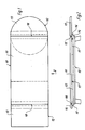
- Fig. 1 eine Draufsicht auf einen Tisch mit zwei Auszugteilen, die jeweils in ihrer Nutzstellung gezeigt sind,
- Fig. 2 eine Ansicht in Richtung des Pfeiles II in Fig. 1, wobei das in Fig. 1 auf der linken Seite gezeigte Auszugteil in seiner Nichtgebrauchsstellung dargestellt ist,
- Fig. 3 eine Draufsicht auf einen Tisch mit vergrößerbarer Tischplatte nach einem weiteren Ausführungsbeispiel der Erfindung,
- Fig. 4 einen Schnitt nach der Linie IV-IV in Fig. 3,
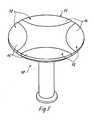
- Fig. 5 eine perspektivische Darstellung eines erfindungsgemäßen Tisches nach einem weiteren Ausführungsbeispiel der Erfindung,
- Fig. 6 eine perspektivische Darstellung des Tisches nach Fig. 5 bei vergrößerter Tischplatte,
- Fig. 7 eine Teildraufsicht auf die Tischplatte des Tisches nach Fig. 5 mit einem aus einem Einschubfach herausgezogenen Auszugteil,
- Fig. 8 eine im wesentlichen der Fig. 7 entsprechende Teildraufsicht, wobei das Auszugteil in seiner gegenüber der Fig. 7 dargestellten Lage um 180° gewendet ist,
- Fig. 9 einen Teilschnitt durch die Tischplatte im Bereich eines gemäß der Lage in Fig. 8 in das Einschubfach eingeschobenen Auszugteiles.
- 1 is a plan view of a table with two pull-out parts, each shown in its use position,
- 2 shows a view in the direction of arrow II in FIG. 1, the pull-out part shown on the left in FIG. 1 being shown in its non-use position,
- 3 is a plan view of a table with an expandable table top according to a further embodiment of the invention,
- 4 shows a section along the line IV-IV in FIG. 3,
- 5 is a perspective view of a table according to the invention according to a further embodiment of the invention,
- 6 is a perspective view of the table of FIG. 5 with an enlarged table top,
- 7 is a partial top view of the table top of the table of FIG. 5 with a pull-out part pulled out of a slot,
- 8 is a partial top view substantially corresponding to FIG. 7, the pull-out part being turned through 180 ° in its position shown in FIG. 7,
- 9 shows a partial section through the table top in the region of a pull-out part pushed into the slot according to the position in FIG. 8.
Der in Figur 1 und 2 schematisch dargestellte und insgesamt mit dem Bezugszeichen 10 versehene Tisch weist eine Tischplatte 11 auf, die durch zwei Auszugteile 12 vergrößerbar ist.The table shown schematically in FIGS. 1 and 2 and provided overall with
Dabei besteht jedes Auszugteil 12 aus einer die nutzbare Tischfläche beträchtlich vergrößernden Platte 13 sowie einem auf dieser Platte 13 befestigten Halteteil 14, welches beim Ausführungsbeispiel gemäß den Figuren 1 und 2 leistenförmig ist.Each pull-out
Insbesondere Figur 2 macht deutlich, daß das leistenförmige Halteteil 14 eine Stirnkante 15 der jeweiligen Platte 13 überragt.FIG. 2 in particular makes it clear that the strip-shaped holding
Das Halteteil 14 ist in seinem auf der Platte 13 aufliegenden Bereich durch eine Kante 16 begrenzt, deren Konturenverlauf demjenigen der Stirnkante 15 der Platte 13 entspricht.The
Wie Figur 2 weiterhin deutlich macht, ist unmittelbar unterhalb der Tischplatte 11 für jedes Auszugteil 12 ein Einschubfach 17 vorgesehen.As FIG. 2 also makes clear, an
Die das jeweilige Einschubfach 17 oberseitig begrenzende Außenkante 18 der Tischplatte 11 weist wiederum den gleichen Konturenverlauf auf wie die Stirnkante 15 der Platte 13 bzw. die entsprechend gestaltete Kante 16 des Halteteiles 14.The
Die Dicke der Platte 13 entspricht der Dicke des Halteteiles 14 und der Dicke der Tischplatte 11. Die lichte Höhe des Einschubfaches 17 ist auf die Dicke der Platte 13 und des Halteteiles 14 abgestimmt, woraus folgende Anwendungsmöglichkeiten resultieren:The thickness of the
In Grundstellung der Auszugteile 12 sind die jeweiligen Platten 13 in die innen vorbestimmten Einschubfächer 17 eingeschoben, so wie dies in Figur 2 auf der linken Seite gezeigt ist. In dieser Position ergänzt das jeweilige Halteteil 14 die Tischplatte 11, ohne diese allerdings nennenswert zu vergrößern.In the basic position of the pull-out
Soll die nutzbare Tischfläche hingegen vergrößert werden, werden die Auszugteile 12 zunächst aus ihren Einschubfächern 17 herausgezogen und dann in der aus Figur 2 auf der rechten Bildseite gezeigten Stellung mit ihren Halteteilen 14 in die Einschubfächer 17 eingeschoben. Die Platten 13 vergrößern nunmehr die insgesamt nutzbare Tischfläche, wie aus Figur 1 unschwer erkennbar ist.If, on the other hand, the usable table surface is to be enlarged, the pull-out
Bedingt durch die Tatsache, daß die Dicke der Platten 13 der Dicke der Tischplatte 11 entspricht und weiterhin bedingt durch die Tatsache, daß die Dicke der Halteteile 14 der lichten Höhe der Einschubfächer 17 entspricht, ergibt sich, daß die Platten 13 durch einfaches Einschieben der Halteteile 14 in die Einschubfächer 17 ausreichend sicher fixiert sind und oberseitig in einer Ebene abschließen mit der Tischplatte 11. Der letztgenannte Vorteil wird auch dann erreicht, wenn lediglich eines der Auszugteile 12 verwendet wird, wie dies in Figur 2 dargestellt ist.Due to the fact that the thickness of the
Der in den Figuren 3 und 4 dargestellte Tisch 10 unterscheidet sich vom Ausführungsbeispiel gemäß den Figuren 1 und 2 lediglich dadurch, daß er eine im wesentlichen quadratische Tischplatte 11 aufweist und mit vier Auszugteilen 12 versehen ist, mittels derer die nutzbare Tischfläche nahezu verdoppelbar ist. Auch hier bestehen die Auszugteile 12 jeweils aus Platten 13 sowie darauf befestigten Halteteilen 14 in Leistenform.The table 10 shown in Figures 3 and 4 differs from the embodiment of Figures 1 and 2 only in that it has an essentially
Handhabung und Funktion der Halteteile 12 entspricht dem Ausführungsbeispiel gemäß den Figuren 1 und 2, auf deren Beschreibung insofern verwiesen werden kann.Handling and function of the
Der in den Figuren 5 bis 9 dargestellte Tisch 10 ist mit einer insgesamt runden Tischplatte 11 ausgestattet. Der Tisch 10 ist mit insgesamt vier Auszugteilen 12 versehen, die es im dargestellten Ausführungsbeispiel ermöglichen, aus einer runden Tischfläche eine quadratische Tischfläche zu machen, was Figur 6 besonders deutlich zeigt.The table 10 shown in Figures 5 to 9 is equipped with an overall
Auch hier bestehen die Auszugteile jeweils aus einer Platte 13 sowie einem damit verbundenen Halteteil 14, welches als scheibenförmig bezeichnet werden kann und eine bikonvexe Grundfläche aufweist, wo hingegen die jeweilige Platte 13 einen etwa viertelkreisförmigen Grundriß aufweist.Here, too, the pull-out parts each consist of a
Jedes scheibenförmige Halteteil 14 steht über die Platte 13 hinaus vor, und zwar im Bereich derer in diesem Falle bogenförmig verlaufenden Stirnkante 15. Entsprechend bogenförmig gestaltet ist die in dem auf der Platte 13 aufliegenden Bereich liegende Kante 16 des Halteteiles 14. Die Einschubfächer 17 zur Aufnahme entweder der Platten 13 oder eines Teiles der Halteteile 14 sind beim Auführungsbeispiel der Erfindung nach den Figuren 5 bis 9 oberseitig wiederum kreisbogenförmig begrenzt, und zwar durch die mit dem Bezugszeichen 18 versehene Außenkante der Tischplatte 11.Each disk-shaped holding
Sind die Platten 13 in die Einschubfächer 17 eingeschoben, so weist der Tisch die aus Figur 5 ersichtliche Form auf. In diesem Falle ergänzen die Halteteile 14 die Tischplatte 11 zu ihrer vollständigen kreisrunden Form.If the
Werden hingegen die Auszugteile 12 zur Vergrößerung der nutzbaren Tischfläche benutzt, so greifen in diesem Falle die Halteteile 14 mit ihren über die Stirnkante 15 der Platten 13 hinaus vorstehenden Bereichen in die Einschubfächer 17 ein. Dabei legt sich die Stirnkante 15 der jeweiligen Platten 13 an die entsprechenden Außenkanten 18 der Tischplatte 11 an so daß wiederum eine in sich geschlossene Tischfläche erzeugt wird.If, on the other hand, the pull-out
Werden alle Auszugteile 12 benutzt, wie in Figur 6 dargestellt, so entsteht ein etwa quadratischer Tisch. Es ist aber ohne weiteres auch möglich, bei geringerem Platzbedarf lediglich eines oder zwei der Auszugteile 12 zu benutzen. Dies ist auch deshalb ohne weiteres möglich, weil durch die Benutzung der Auszugteile 12 eine Änderung der Höhenlage der nutzbaren Tischfläche nicht eintritt.If all pull-out
Wie Figur 9 deutlich zeigt, ist das Einschubfach 17 durch eine Tragplatte 19 begrenzt, die mit einer Beschichtung 20 aus einem weichen und elastischen Material, vorzugsweise aus Flockenfilz, versehen ist. Durch eine derartige Beschichtung 20 wird erreicht, daß das jeweils in das Einschubfach 17 eingreifende Teil des Auszugteiles 12 praktisch spielfrei innerhalb des Einschubfaches 17 gehalten wird.As FIG. 9 clearly shows, the
Es sei an dieser Stelle ausdrücklich darauf hingewiesen, daß eine derartige Ausstattung des Einschubfaches 17 selbstverständlich auch bei den Ausführungsbeispielen nach den Figuren 1 bis 4 denkbar und möglich ist.At this point, it should be expressly pointed out that such a configuration of the
Das gleiche gilt auch für die aus den Figuren 7 bis 9 ersichtlichen Magnete 21 und Magnetgegenstücke 22, welche einerseits an den Außenkanten 18 der Tischplatte 11 und andererseits an den Stirnkanten 15 der Platten 13 bzw. den Kanten 16 der Halteteile 14 angeordnet sind. Durch diese Magnete 21 und Magnetgegenstücke 22 wird die Lage jedes Auszugteiles innerhalb des Einschubfaches 17 auf einfache Art und Weise gegen unbeabsichtigtes Verschieben gesichert und eine feste Lagesicherung erreicht.The same also applies to the
Hinsichtlich des Ausführungsbeispieles der Erfindung nach den Figuren 5 bis 9 ist noch zu sagen, daß es sowohl aus fertigungstechnischen Gründen wie auch aus formgestalterischen Gründen vorteilhaft ist, die Halteteile 14 hin sichtlich ihrer Grundfläche so zu gestalten, daß nicht nur eine bikonvexe Form erreicht wird, sondern daß darüber hinaus auch noch die Krümmungsradien gleich sind.With regard to the exemplary embodiment of the invention according to FIGS. 5 to 9, it should also be said that it is advantageous both for production-related reasons and for design reasons to hold the holding
Die Ecken der viertelkreisförmig gestalteten Platten 13 können selbstverständlich mehr oder weniger stark abgerundet sein.The corners of the quarter-
Als Material für die Tischplatte 11 nebst der Auszugteile 12 kommen sowohl Holz wie auch Kunststoff oder andere im Möbelbau übliche Materialien in Frage. Ebenso können Materialkombinationen verwendet werden, beispielsweise können die Auszugteile 12 aus einem anderen Material hergestellt sein wie die Tischplatte 11. Darüber hinaus besteht auch noch die Möglichkeit, die Platte 13 und die Halteteile 14 jedes Auszugteiles 12 aus unterschiedlichen Materialien zu fertigen.As material for the
Die vorstehenden Ausführungen sollen nur andeutungsweise zeigen, welche gestalterischen Möglichkeiten durch die erfindungsgemäße Konstruktion zusätzlich zu den rein technischen Vorteilen eröffnet werden.The above explanations are only intended to indicate the design options which are opened up by the construction according to the invention in addition to the purely technical advantages.
Claims (7)
Applications Claiming Priority (2)
| Application Number | Priority Date | Filing Date | Title |
|---|---|---|---|
| DE19863635083 DE3635083A1 (en) | 1986-10-15 | 1986-10-15 | TABLE WITH A TABLE TOP EXTENDABLE BY AT LEAST ONE EXTRACTING PART |
| DE3635083 | 1986-10-15 |
Publications (2)
| Publication Number | Publication Date |
|---|---|
| EP0264084A2 true EP0264084A2 (en) | 1988-04-20 |
| EP0264084A3 EP0264084A3 (en) | 1989-07-12 |
Family
ID=6311770
Family Applications (1)
| Application Number | Title | Priority Date | Filing Date |
|---|---|---|---|
| EP87114812A Withdrawn EP0264084A3 (en) | 1986-10-15 | 1987-10-10 | Table extensible by at least one leaf |
Country Status (3)
| Country | Link |
|---|---|
| US (1) | US4815393A (en) |
| EP (1) | EP0264084A3 (en) |
| DE (1) | DE3635083A1 (en) |
Cited By (1)
| Publication number | Priority date | Publication date | Assignee | Title |
|---|---|---|---|---|
| EP3050460A4 (en) * | 2013-09-23 | 2017-05-31 | Casanovas Rodriguez, José Miguel | Piece of furniture having a convertible work surface |
Families Citing this family (15)
| Publication number | Priority date | Publication date | Assignee | Title |
|---|---|---|---|---|
| US5207162A (en) * | 1992-04-16 | 1993-05-04 | Phillip Mismas | Expandable table |
| USD358954S (en) | 1993-04-06 | 1995-06-06 | Allibert | Table |
| US5485795A (en) * | 1995-03-29 | 1996-01-23 | Williams; Jeanne L. | Free standing extension table and method of manufacture |
| US5664689A (en) * | 1995-05-02 | 1997-09-09 | Mirlisena, Sr.; John Raymond | Shelf organizer |
| US6907829B2 (en) * | 2003-04-03 | 2005-06-21 | Mii, Inc. | Shelf extension |
| US7509913B1 (en) * | 2003-05-14 | 2009-03-31 | Franklin Eagle | Table bridge |
| US7226125B2 (en) * | 2004-04-16 | 2007-06-05 | Biofit Engineered Products | Convertible bench table with magnetic locks |
| ITMI20050283A1 (en) * | 2005-02-23 | 2006-08-24 | Molds & Moulds Inc | POLYVALENT TABLE FOR FURNISHING |
| US7849803B2 (en) * | 2007-08-24 | 2010-12-14 | Century Furniture Llc | Expandable table and center alignment assembly for such an expandable table |
| US7950336B2 (en) * | 2008-07-30 | 2011-05-31 | Aero Manufacturing Company, Inc. | Table assembly, jointed table, and method of creating a clean interstice |
| US8161891B2 (en) | 2010-04-01 | 2012-04-24 | Blue Sky Innovation Group, Inc. | Expandable table |
| USD644455S1 (en) | 2010-05-03 | 2011-09-06 | Steelcase Inc. | Table |
| USD644457S1 (en) | 2010-05-03 | 2011-09-06 | Steelcase Inc. | Table |
| US10555601B1 (en) * | 2019-01-22 | 2020-02-11 | Theresa Oblak | Expandable table assembly |
| IT202000001621A1 (en) * | 2020-01-28 | 2021-07-28 | B 4 Living Spa | EXTENDABLE TABLE. |
Family Cites Families (18)
| Publication number | Priority date | Publication date | Assignee | Title |
|---|---|---|---|---|
| DE200581C (en) * | ||||
| US1088612A (en) * | 1911-04-19 | 1914-02-24 | Victor F Neumann | Extension-table. |
| US1524943A (en) * | 1923-10-25 | 1925-02-03 | William N Miller | Disappearing structure |
| DE564246C (en) * | 1931-05-01 | 1932-11-17 | Fi Ti Wi Finsterwalder Tischfa | Table with a table top that can be enlarged |
| US2305343A (en) * | 1939-08-09 | 1942-12-15 | Helen M Gadbois | Work support for portable electric sewing machines |
| US2492139A (en) * | 1946-07-12 | 1949-12-27 | Adlai H Eliason | Means for the expansion of circular tables |
| US2614013A (en) * | 1948-12-11 | 1952-10-14 | Langius Manuel | Extension table with detachable end leaves |
| US2703740A (en) * | 1951-12-06 | 1955-03-08 | Cochard Jean Marie | Segment extension leaves for round or oval tables |
| DE1744131U (en) * | 1957-02-14 | 1957-05-02 | Oeseder Moebel Ind Mathias Wie | TABLE. |
| FR1340068A (en) * | 1962-12-03 | 1963-10-11 | Extendable table | |
| FR1383125A (en) * | 1963-11-04 | 1964-12-24 | B H C Hyp & Claeys Successeurs | Improvement in slide and slide devices for table extensions |
| US3259082A (en) * | 1965-04-23 | 1966-07-05 | Carol N Williams | Portable shelf |
| US3494307A (en) * | 1967-10-11 | 1970-02-10 | Vladimir Kagan | Extension table |
| GB1314063A (en) * | 1970-02-12 | 1973-04-18 | Finestone P I | Table top units |
| DK194275A (en) * | 1975-05-05 | 1976-11-06 | H F Bertelsen | OVAL TABLE WITH DISTRIBUTED TABLE TOP |
| DK140165C (en) * | 1975-05-05 | 1979-11-26 | H F Bertelsen | TABLE WITH DISTRIBUTED TABLE TOP |
| CH629377A5 (en) * | 1978-07-24 | 1982-04-30 | Girsberger Ag | Extensible table |
| DE3523584A1 (en) * | 1985-07-02 | 1987-01-08 | Rosenthal Ag | TABLE WITH CHANGEABLE TOP |
-
1986
- 1986-10-15 DE DE19863635083 patent/DE3635083A1/en active Granted
-
1987
- 1987-10-10 EP EP87114812A patent/EP0264084A3/en not_active Withdrawn
- 1987-10-13 US US07/108,479 patent/US4815393A/en not_active Expired - Fee Related
Cited By (1)
| Publication number | Priority date | Publication date | Assignee | Title |
|---|---|---|---|---|
| EP3050460A4 (en) * | 2013-09-23 | 2017-05-31 | Casanovas Rodriguez, José Miguel | Piece of furniture having a convertible work surface |
Also Published As
| Publication number | Publication date |
|---|---|
| US4815393A (en) | 1989-03-28 |
| DE3635083C2 (en) | 1992-01-02 |
| DE3635083A1 (en) | 1988-04-28 |
| EP0264084A3 (en) | 1989-07-12 |
Similar Documents
| Publication | Publication Date | Title |
|---|---|---|
| DE3635083C2 (en) | ||
| DE8106304U1 (en) | STORAGE DEVICE | |
| DE10242518A1 (en) | Drawer has flexible partition which divides its internal space consisting of strip of textile or rubber mounted on posts which fit into holes in pattern in drawer base | |
| DE29712619U1 (en) | Device for holding objects | |
| EP0102553A1 (en) | Device for displaying flat articles | |
| DE8627525U1 (en) | Table with a table top that can be extended by at least one pull-out part | |
| DE202015105784U1 (en) | Shelf with simple connection technology | |
| DE3516944A1 (en) | CABINET DRAWER MADE OF MOLDED PLASTIC | |
| DE4410397C1 (en) | Piece of furniture | |
| DE2512189C3 (en) | Model kit with true-to-scale furnishings | |
| DE1654628A1 (en) | Furniture kit | |
| EP0291058A1 (en) | System for assembling furniture, boxes, partitions or the like | |
| DE2449961A1 (en) | Dentists hygienically sealed chest of drawers - has full width resilient seal underneath top drawer engaging over next drawer | |
| DE4308448C2 (en) | Kit for retrofitting a desk or work table | |
| DE2202444A1 (en) | FURNITURE SET | |
| CH401908A (en) | Containers for forms and the like | |
| AT262544B (en) | Device for forming compartments on counters, shelves or other panels | |
| DE202019105273U1 (en) | Insertion device for play furniture elements and modular play furniture system comprising at least one insertion device and at least one play furniture element | |
| DE202021104959U1 (en) | Device for connecting a first table to a second table | |
| DE8304190U1 (en) | OFFICE CABINET | |
| DE7637192U1 (en) | CONSTRUCTION KIT FOR SHELVES OR CABINETS | |
| DE8702304U1 (en) | Cheese box open on one side | |
| DE1429531A1 (en) | Adjustable supports for book shelves or the like. | |
| CH279236A (en) | Device for dividing containers. | |
| DE29711475U1 (en) | drawer |
Legal Events
| Date | Code | Title | Description |
|---|---|---|---|
| PUAI | Public reference made under article 153(3) epc to a published international application that has entered the european phase |
Free format text: ORIGINAL CODE: 0009012 |
|
| AK | Designated contracting states |
Kind code of ref document: A2 Designated state(s): AT BE CH DE ES FR GB IT LI NL |
|
| PUAL | Search report despatched |
Free format text: ORIGINAL CODE: 0009013 |
|
| AK | Designated contracting states |
Kind code of ref document: A3 Designated state(s): AT BE CH DE ES FR GB IT LI NL |
|
| 17P | Request for examination filed |
Effective date: 19890808 |
|
| 17Q | First examination report despatched |
Effective date: 19901031 |
|
| STAA | Information on the status of an ep patent application or granted ep patent |
Free format text: STATUS: THE APPLICATION IS DEEMED TO BE WITHDRAWN |
|
| 18D | Application deemed to be withdrawn |
Effective date: 19910226 |