EP0264110A1 - Dispositif électromagnétique, notamment bobinage électromagnétique - Google Patents
Dispositif électromagnétique, notamment bobinage électromagnétique Download PDFInfo
- Publication number
- EP0264110A1 EP0264110A1 EP19870114963 EP87114963A EP0264110A1 EP 0264110 A1 EP0264110 A1 EP 0264110A1 EP 19870114963 EP19870114963 EP 19870114963 EP 87114963 A EP87114963 A EP 87114963A EP 0264110 A1 EP0264110 A1 EP 0264110A1
- Authority
- EP
- European Patent Office
- Prior art keywords
- arrangement according
- electromagnetic arrangement
- film
- electromagnetic
- electrically
- Prior art date
- Legal status (The legal status is an assumption and is not a legal conclusion. Google has not performed a legal analysis and makes no representation as to the accuracy of the status listed.)
- Withdrawn
Links
- 238000004804 winding Methods 0.000 title claims abstract description 63
- 239000004020 conductor Substances 0.000 claims abstract description 51
- 239000002184 metal Substances 0.000 claims abstract description 23
- 229910052751 metal Inorganic materials 0.000 claims abstract description 23
- 229920003023 plastic Polymers 0.000 claims abstract description 18
- 239000004033 plastic Substances 0.000 claims abstract description 18
- 239000002985 plastic film Substances 0.000 claims abstract description 18
- 229920006255 plastic film Polymers 0.000 claims abstract description 18
- 239000011248 coating agent Substances 0.000 claims abstract description 8
- 238000000576 coating method Methods 0.000 claims abstract description 8
- 239000000843 powder Substances 0.000 claims description 6
- 239000000428 dust Substances 0.000 claims description 3
- 238000009413 insulation Methods 0.000 claims description 3
- 230000002093 peripheral effect Effects 0.000 claims 1
- 239000010410 layer Substances 0.000 description 18
- -1 Polypropylen Polymers 0.000 description 9
- 229920001577 copolymer Polymers 0.000 description 9
- 239000011888 foil Substances 0.000 description 8
- OKTJSMMVPCPJKN-UHFFFAOYSA-N Carbon Chemical compound [C] OKTJSMMVPCPJKN-UHFFFAOYSA-N 0.000 description 5
- 229920000642 polymer Polymers 0.000 description 5
- XLYOFNOQVPJJNP-UHFFFAOYSA-N water Substances O XLYOFNOQVPJJNP-UHFFFAOYSA-N 0.000 description 5
- 150000001875 compounds Chemical class 0.000 description 4
- 238000004519 manufacturing process Methods 0.000 description 4
- 238000000465 moulding Methods 0.000 description 4
- 238000013461 design Methods 0.000 description 3
- 239000000835 fiber Substances 0.000 description 3
- 238000000034 method Methods 0.000 description 3
- 229920000728 polyester Polymers 0.000 description 3
- 229920001155 polypropylene Polymers 0.000 description 3
- 230000008569 process Effects 0.000 description 3
- URLKBWYHVLBVBO-UHFFFAOYSA-N Para-Xylene Chemical group CC1=CC=C(C)C=C1 URLKBWYHVLBVBO-UHFFFAOYSA-N 0.000 description 2
- 239000004952 Polyamide Substances 0.000 description 2
- 239000004642 Polyimide Substances 0.000 description 2
- 239000004721 Polyphenylene oxide Substances 0.000 description 2
- 239000004743 Polypropylene Substances 0.000 description 2
- QQONPFPTGQHPMA-UHFFFAOYSA-N Propene Chemical compound CC=C QQONPFPTGQHPMA-UHFFFAOYSA-N 0.000 description 2
- 230000015572 biosynthetic process Effects 0.000 description 2
- 229910052799 carbon Inorganic materials 0.000 description 2
- 229920002678 cellulose Polymers 0.000 description 2
- 229920001940 conductive polymer Polymers 0.000 description 2
- 230000005611 electricity Effects 0.000 description 2
- 150000002148 esters Chemical class 0.000 description 2
- 230000005284 excitation Effects 0.000 description 2
- 229910002804 graphite Inorganic materials 0.000 description 2
- 239000010439 graphite Substances 0.000 description 2
- IEQIEDJGQAUEQZ-UHFFFAOYSA-N phthalocyanine Chemical compound N1C(N=C2C3=CC=CC=C3C(N=C3C4=CC=CC=C4C(=N4)N3)=N2)=C(C=CC=C2)C2=C1N=C1C2=CC=CC=C2C4=N1 IEQIEDJGQAUEQZ-UHFFFAOYSA-N 0.000 description 2
- 229920003055 poly(ester-imide) Polymers 0.000 description 2
- 229920000052 poly(p-xylylene) Polymers 0.000 description 2
- 229920002492 poly(sulfone) Polymers 0.000 description 2
- 229920002647 polyamide Polymers 0.000 description 2
- 229920002480 polybenzimidazole Polymers 0.000 description 2
- 239000004417 polycarbonate Substances 0.000 description 2
- 229920000515 polycarbonate Polymers 0.000 description 2
- 229920001721 polyimide Polymers 0.000 description 2
- 229920000098 polyolefin Polymers 0.000 description 2
- 229920002223 polystyrene Polymers 0.000 description 2
- 229920002635 polyurethane Polymers 0.000 description 2
- 239000004814 polyurethane Substances 0.000 description 2
- 229920000915 polyvinyl chloride Polymers 0.000 description 2
- 229920002620 polyvinyl fluoride Polymers 0.000 description 2
- 229920002981 polyvinylidene fluoride Polymers 0.000 description 2
- 229920005989 resin Polymers 0.000 description 2
- 239000011347 resin Substances 0.000 description 2
- 229920001169 thermoplastic Polymers 0.000 description 2
- OEPOKWHJYJXUGD-UHFFFAOYSA-N 2-(3-phenylmethoxyphenyl)-1,3-thiazole-4-carbaldehyde Chemical compound O=CC1=CSC(C=2C=C(OCC=3C=CC=CC=3)C=CC=2)=N1 OEPOKWHJYJXUGD-UHFFFAOYSA-N 0.000 description 1
- RYGMFSIKBFXOCR-UHFFFAOYSA-N Copper Chemical compound [Cu] RYGMFSIKBFXOCR-UHFFFAOYSA-N 0.000 description 1
- YCKRFDGAMUMZLT-UHFFFAOYSA-N Fluorine atom Chemical compound [F] YCKRFDGAMUMZLT-UHFFFAOYSA-N 0.000 description 1
- 229920000271 Kevlar® Polymers 0.000 description 1
- 239000002033 PVDF binder Substances 0.000 description 1
- 244000089486 Phragmites australis subsp australis Species 0.000 description 1
- 229920002845 Poly(methacrylic acid) Polymers 0.000 description 1
- 239000004693 Polybenzimidazole Substances 0.000 description 1
- 239000004698 Polyethylene Substances 0.000 description 1
- 239000002202 Polyethylene glycol Substances 0.000 description 1
- 229920000265 Polyparaphenylene Polymers 0.000 description 1
- 239000004734 Polyphenylene sulfide Substances 0.000 description 1
- 239000004793 Polystyrene Substances 0.000 description 1
- 229920001756 Polyvinyl chloride acetate Polymers 0.000 description 1
- 229920001328 Polyvinylidene chloride Polymers 0.000 description 1
- 229910000831 Steel Inorganic materials 0.000 description 1
- 239000000370 acceptor Substances 0.000 description 1
- 239000012790 adhesive layer Substances 0.000 description 1
- 229920000180 alkyd Polymers 0.000 description 1
- HSFWRNGVRCDJHI-UHFFFAOYSA-N alpha-acetylene Natural products C#C HSFWRNGVRCDJHI-UHFFFAOYSA-N 0.000 description 1
- XAGFODPZIPBFFR-UHFFFAOYSA-N aluminium Chemical compound [Al] XAGFODPZIPBFFR-UHFFFAOYSA-N 0.000 description 1
- 229920003180 amino resin Polymers 0.000 description 1
- 239000004760 aramid Substances 0.000 description 1
- 229920003235 aromatic polyamide Polymers 0.000 description 1
- 238000005452 bending Methods 0.000 description 1
- 230000005540 biological transmission Effects 0.000 description 1
- 239000006229 carbon black Substances 0.000 description 1
- MMCOUVMKNAHQOY-UHFFFAOYSA-N carbonoperoxoic acid Chemical class OOC(O)=O MMCOUVMKNAHQOY-UHFFFAOYSA-N 0.000 description 1
- 239000001913 cellulose Substances 0.000 description 1
- 229920003086 cellulose ether Polymers 0.000 description 1
- 238000006243 chemical reaction Methods 0.000 description 1
- 239000011231 conductive filler Substances 0.000 description 1
- 238000010276 construction Methods 0.000 description 1
- 238000011161 development Methods 0.000 description 1
- 125000005442 diisocyanate group Chemical group 0.000 description 1
- 238000009826 distribution Methods 0.000 description 1
- 238000004870 electrical engineering Methods 0.000 description 1
- 239000012799 electrically-conductive coating Substances 0.000 description 1
- 238000007786 electrostatic charging Methods 0.000 description 1
- 239000003822 epoxy resin Substances 0.000 description 1
- 229920001038 ethylene copolymer Polymers 0.000 description 1
- 230000002349 favourable effect Effects 0.000 description 1
- 238000010285 flame spraying Methods 0.000 description 1
- 229910052731 fluorine Inorganic materials 0.000 description 1
- 239000011737 fluorine Substances 0.000 description 1
- 239000003365 glass fiber Substances 0.000 description 1
- LNEPOXFFQSENCJ-UHFFFAOYSA-N haloperidol Chemical compound C1CC(O)(C=2C=CC(Cl)=CC=2)CCN1CCCC(=O)C1=CC=C(F)C=C1 LNEPOXFFQSENCJ-UHFFFAOYSA-N 0.000 description 1
- 230000006872 improvement Effects 0.000 description 1
- 229910052740 iodine Inorganic materials 0.000 description 1
- 239000011630 iodine Substances 0.000 description 1
- 239000004761 kevlar Substances 0.000 description 1
- 238000010030 laminating Methods 0.000 description 1
- 239000000463 material Substances 0.000 description 1
- 235000013372 meat Nutrition 0.000 description 1
- 238000001465 metallisation Methods 0.000 description 1
- 125000002496 methyl group Chemical group [H]C([H])([H])* 0.000 description 1
- 239000000203 mixture Substances 0.000 description 1
- 238000012986 modification Methods 0.000 description 1
- 230000004048 modification Effects 0.000 description 1
- 239000003973 paint Substances 0.000 description 1
- 239000012071 phase Substances 0.000 description 1
- 229920001568 phenolic resin Polymers 0.000 description 1
- 229920001197 polyacetylene Polymers 0.000 description 1
- 229920002239 polyacrylonitrile Polymers 0.000 description 1
- 238000006068 polycondensation reaction Methods 0.000 description 1
- 229920000647 polyepoxide Polymers 0.000 description 1
- 229920001225 polyester resin Polymers 0.000 description 1
- 239000004645 polyester resin Substances 0.000 description 1
- 229920000570 polyether Polymers 0.000 description 1
- 229920006393 polyether sulfone Polymers 0.000 description 1
- 229920000573 polyethylene Polymers 0.000 description 1
- 229920001223 polyethylene glycol Polymers 0.000 description 1
- 229920006324 polyoxymethylene Polymers 0.000 description 1
- 229920006380 polyphenylene oxide Polymers 0.000 description 1
- 229920000069 polyphenylene sulfide Polymers 0.000 description 1
- 229920000128 polypyrrole Polymers 0.000 description 1
- 229920001343 polytetrafluoroethylene Polymers 0.000 description 1
- 239000004810 polytetrafluoroethylene Substances 0.000 description 1
- 229920000123 polythiophene Polymers 0.000 description 1
- 229920002689 polyvinyl acetate Polymers 0.000 description 1
- 239000011118 polyvinyl acetate Substances 0.000 description 1
- 239000004800 polyvinyl chloride Substances 0.000 description 1
- 239000005033 polyvinylidene chloride Substances 0.000 description 1
- 238000007639 printing Methods 0.000 description 1
- 238000007789 sealing Methods 0.000 description 1
- 229920002050 silicone resin Polymers 0.000 description 1
- 238000004544 sputter deposition Methods 0.000 description 1
- 239000010959 steel Substances 0.000 description 1
- 229920003048 styrene butadiene rubber Polymers 0.000 description 1
- 239000000126 substance Substances 0.000 description 1
- KKEYFWRCBNTPAC-UHFFFAOYSA-L terephthalate(2-) Chemical compound [O-]C(=O)C1=CC=C(C([O-])=O)C=C1 KKEYFWRCBNTPAC-UHFFFAOYSA-L 0.000 description 1
- 238000012549 training Methods 0.000 description 1
- 230000009466 transformation Effects 0.000 description 1
- 229920006305 unsaturated polyester Polymers 0.000 description 1
- 238000007740 vapor deposition Methods 0.000 description 1
- 239000012808 vapor phase Substances 0.000 description 1
Images


Classifications
-
- H—ELECTRICITY
- H02—GENERATION; CONVERSION OR DISTRIBUTION OF ELECTRIC POWER
- H02K—DYNAMO-ELECTRIC MACHINES
- H02K3/00—Details of windings
- H02K3/04—Windings characterised by the conductor shape, form or construction, e.g. with bar conductors
- H02K3/26—Windings characterised by the conductor shape, form or construction, e.g. with bar conductors consisting of printed conductors
-
- H—ELECTRICITY
- H01—ELECTRIC ELEMENTS
- H01F—MAGNETS; INDUCTANCES; TRANSFORMERS; SELECTION OF MATERIALS FOR THEIR MAGNETIC PROPERTIES
- H01F17/00—Fixed inductances of the signal type
- H01F17/0006—Printed inductances
-
- H—ELECTRICITY
- H01—ELECTRIC ELEMENTS
- H01F—MAGNETS; INDUCTANCES; TRANSFORMERS; SELECTION OF MATERIALS FOR THEIR MAGNETIC PROPERTIES
- H01F5/00—Coils
-
- H—ELECTRICITY
- H01—ELECTRIC ELEMENTS
- H01F—MAGNETS; INDUCTANCES; TRANSFORMERS; SELECTION OF MATERIALS FOR THEIR MAGNETIC PROPERTIES
- H01F5/00—Coils
- H01F5/003—Printed circuit coils
Definitions
- the invention relates to an electromagnetic arrangement, in particular an electromagnetic winding with current conductor windings which are electrically insulated from one another.
- Electro coils in e.g. Electro coils, electric motors (field and armature windings, also as squirrel-cage rotors), transformers etc. are made of metal, especially copper wire and are therefore expensive, heavy and also sluggish or material and production-related.
- the object of the invention is the formation of electromagnetic windings or field coils of various types used in electrical engineering, which avoid these disadvantages and are also space-saving and applicable in new designs.
- the invention consists in an electromagnetic arrangement of the aforementioned Kind, wherein the current conductor windings are designed as an electrically conductive film.
- the individual current conductor windings are not wound individually next to one another in layers, but primarily one above the other in layers.
- the heat generated in the winding can therefore be removed in layers laterally to the foil pressure side.
- the electromagnetic winding according to the invention can be used particularly in the lower power range, for which its electrokinetically lightweight, low-inertia structure is particularly advantageous (loudspeaker coils, choke coils, transformers in circuit boards).
- the electromagnetic windings constructed from foils according to the invention are also of particular interest for the transformation of the kinetic energy contained in flowing water or air masses into electrical current. They are particularly suitable for the production of modular, tubular and very light power generators. Modular electricity generators allow various, depending on the availability of raw energy and the need for useful energy To connect generator units electrically in parallel or in series.
- the mechanical power conversion usually takes place in a machine separate from the electrical generator (e.g. turbine or wind turbine).
- the parts of the generator are formed directly by the parts of the mechanical power transmission, in that the electrical windings are integrated in them.
- the construction of a wind or hydropower plant from generator modules thus opens up great advantages for the individual, flexible matching of energy supply and demand.
- the foil-shaped current conductors can either consist of thin metal foils which are provided on one or both sides with electrically insulating plastic, or can preferably be made of metal, for example from the vapor phase or galvanically coated electrically insulating plastic.
- Various processes are known for the surface coating of plastics with conductive materials, such as chemical and galvanic metallization processes, laminating with metal foils, metal vapor deposition, flame spraying, cathode sputtering, plasma processes and the use of metallic or graphite-filled paints.
- electrostatic charging of the plastic films or pretreatment with Adhesive layers can be used to apply conductive surface coverings.
- the current conductor winding according to the invention can also consist of an electrically conductive plastic, for which both conductive polymer compounds and polymers with so-called intrinsic electrical conductivity can be used.
- the conductive polymer compounds are plastics with incorporated conductive fillers, e.g. Aluminum powder, fiber, flake, carbon or graphite fiber, graphite powder or carbon black, steel fiber; metallized glass fibers or spheres.
- Suitable intrinsically conductive plastics are plastics doped with suitable electron donors (e.g. metal atoms) or electron acceptors (e.g. iodine atoms), e.g.
- the electrically insulating layer between the turns of the electrically conductive plastic film can either be connected to it or be separately wound between.
- a particularly advantageous embodiment consists in that an electrically insulating plastic film is provided with a zone-like or line-like pattern of current conductors - for example made of bound carbon or metal powder, e.g. is printed, with a single plastic web turn a plurality of conductors can be assigned to each other, either in parallel connection of the individual turns or by special arrangement also in series connection.
- the interconnection of individual current conductor areas to higher numbers of turns can take place, for example, by means of special contacts at the associated ends of the current conductor areas to be connected.
- a zone-by-zone or strip-like division option between electrically conductive tracks and electrically insulating film areas enables a large number of special application possibilities.
- the design of the electrical current conductors as foils enables e.g. the winding of tubes, the tube wall of which practically consists of winding layers of an electromagnetic winding, so that such a tube - correspondingly encased in waterproof plastic - can also be used in water
- zone-by-zone or zone-by-zone current conductors are arranged in coordination with the phase position of the field magnets, a simplified design of the commutators is also possible.
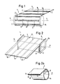
- FIG. 1 and 2 as well as 2a show three basic embodiments of the formation and arrangement of a foil metal coating 4 on an electrically insulating plastic foil 5 as insulation of the individual current conductor windings 2 from one another, specifically schematically as an electromagnetic winding 1 with one coil each -Longitudinal axis S shown.
- the current conductor windings 2 are arranged in the longitudinal direction of the coil 1a as a strip 9 on the electrically insulating plastic film 5, which at the same time forms insulating zone areas 8 between the current conductors.
- the current conductor windings 2 are provided in the circumferential direction on the electrically insulating plastic film 5, which is wound around a rectangular instead of round (Fig. 1) coil core with the longitudinal axis S such that the individual current conductor windings 2 for Avoiding bending - tensile - forces is arranged on the inside of the plastic film 5, the current conductor windings 2, for example can also be present as a self-contained metal layer (2) made of meat powder.
- the individual current conductor windings 2 can be arranged on the plastic film 5 in different distribution and density - for example with a gap to one another.
- the respective ends - inner end A and outer end B (FIG. 2) or side end C (FIG. 1) - are provided as contacts for the electrical connection of the conductor windings.
- FIG. 2a shows an electromagnetic winding 1 with a current conductor winding 2 which is formed continuously between the two ends, that is to say not provided with a metal coating 4 and is not divided into strips 9, specifically at the front edge as a cross section through the current conductor winding 2.
- Both the thickness of the insulating plastic film 5 and the thickness of the current conductor 2 or the metal coating 4 or the metal layer 7 made of powder containing metal dust can be only a few ⁇ m, depending on the power consumption required.
- the current conductor 2 and the plastic film 5 can either be firmly connected to one another (FIG. 1, FIG. 2) or wound independently of one another on the coil 1a (for example in the embodiment according to FIG. 2a).
- the current conductors 2 - whether in strips 9 or as continuous tracks according to FIG. 2a - preferably also consist of electrically conductive plastic, which are listed as examples in the introduction.
- electromagnetic windings are easier to manufacture, lighter, cheaper and also more compact, and more advantageously can be adapted to different applications in a wide variety of ways.
- FIGS. 3 to 7 show a specific exemplary embodiment of a special application, namely a tubular generator for using flow energies of water or air.
- the electromagnetic windings 1 are arranged in the form of strips 9 on an electrically conductive cylindrical tube 11, which, similar to FIG. 1, can also be wound in layers one above the other by means of electrically insulating plastic film 5 (see FIGS. 6 and 7, layers 10).
- the side ends C of the individual current conductor strips 9 are either connected to one another at the ends of the tube 11 lying next to one another (FIG. 6) or diametrically opposed to one another in parallel connection via combination contacts 15 (FIG. 3), so that closed current conductor loops are formed in this way surrender.
- This diametrically extending electrical connection of the strips 9 or their layers 10 via the end face of the tube 11 by means of their combination contacts 15 takes place according to FIG. 7 via end caps or an end cap arrangement 14, with which the cylindrical tube 11 is rotatably mounted in a rotary bearing 20.
- the current is also drawn off via commutators or brushes 19 in the center of the end cap arrangement 14 (FIG. 7).
- a permanent magnet 12 (FIGS. 3 and 4) either arranged in the interior of the tube 11 or an electromagnet can be used for current excitation.
- the permanent magnet can also be arranged outside the tube 11 constructed from foil-like electromagnetic windings.
- the film-like windings 2 serve both the structure and the strength of the tubular body.
- Such generators can therefore be lightweight and - constructed by means of plastic locking or sealing on all sides and can even operate within the flowing water, the more favorable dielectric constant within the water offering additional advantages.
- the drive of the tube 11 as a generator can be arranged either on its circumference or on the inside of the tube in the form of guide surfaces.
- the current conductor tracks can be arranged very closely and in various forms on the film 5.
- This type of attachment is also particularly suitable for electromagnetic wound according to FIG. 1 but arranged flat around a plate-like transformer core Windings 1 as a light and flat transformer in modern circuits.
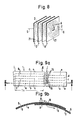
- Each electromagnetic winding 2 according to FIG. 8 can also be arranged spirally on a very thin plate or film as surface 21, the winding 2 being arranged spirally around the coil axis S (or around the electromagnetic axis). These surfaces can then be arranged close to each other in packages, the inner and outer ends A and B of which can be connected either in series or in parallel with one another.
- FIG. 9 shows a section along the line III-III in FIG. 9a.
- the track a is connected to the track b (or the tracks b with c, c with d and d with e) during the winding of the first layer of a coil, the bridging contacts 16 being connected from the top to the bottom of an electrically insulating Pass plastic film 5 through. This ensures that the traces or current conductors a - e of the first layer of film are connected to one another in series before this series connection is continued in the next layer of film above.
- the bridging contacts can be firmly fused to the ends of the current conductor paths to be bridged.
- the printing or the arrangement of the current conductors 2 on the electrically insulating film can also be present in completely closed loops, the lengths of which run along the circumference are connected to one another by current paths 13 running at the end around 180 ° of the circumference.
Landscapes
- Engineering & Computer Science (AREA)
- Power Engineering (AREA)
- Microelectronics & Electronic Packaging (AREA)
- Coils Of Transformers For General Uses (AREA)
- Surgical Instruments (AREA)
- Power Steering Mechanism (AREA)
- Vehicle Body Suspensions (AREA)
- Windings For Motors And Generators (AREA)
Applications Claiming Priority (2)
| Application Number | Priority Date | Filing Date | Title |
|---|---|---|---|
| DE3635152 | 1986-10-15 | ||
| DE19863635152 DE3635152A1 (de) | 1986-10-15 | 1986-10-15 | Elektromagnetische anordnung, insbesondere elektromagnetische wicklung |
Publications (1)
| Publication Number | Publication Date |
|---|---|
| EP0264110A1 true EP0264110A1 (fr) | 1988-04-20 |
Family
ID=6311796
Family Applications (1)
| Application Number | Title | Priority Date | Filing Date |
|---|---|---|---|
| EP19870114963 Withdrawn EP0264110A1 (fr) | 1986-10-15 | 1987-10-13 | Dispositif électromagnétique, notamment bobinage électromagnétique |
Country Status (3)
| Country | Link |
|---|---|
| EP (1) | EP0264110A1 (fr) |
| JP (1) | JPS63108702A (fr) |
| DE (1) | DE3635152A1 (fr) |
Cited By (8)
| Publication number | Priority date | Publication date | Assignee | Title |
|---|---|---|---|---|
| WO1992016043A1 (fr) * | 1991-03-01 | 1992-09-17 | Carlstedt Elektronik Ab | Bloc d'alimentation a courant continu et a tension basse |
| EP0670621A1 (fr) * | 1994-03-04 | 1995-09-06 | Philips Patentverwaltung GmbH | Moteur électrique avec un stateur et un roteur |
| EP0730778A4 (fr) * | 1992-12-14 | 1995-10-02 | Kern K N Chang | Transformateur flexible adapte notamment a un fonctionnement a haute tension |
| GB2308922A (en) * | 1995-12-31 | 1997-07-09 | Daewoo Electronics Co Ltd | Flexible coil structure |
| WO1998011649A1 (fr) * | 1996-09-13 | 1998-03-19 | Philips Electronics N.V. | Dispositif electromecanique, configuration de bobine pour ledit dispositif, et appareil de stockage et/ou de reproduction d'information comprenant ledit dispositif |
| EP1061768A3 (fr) * | 1999-06-18 | 2003-04-09 | Murata Manufacturing Co., Ltd. | Transformateur,dispositif de haut-parleur et système de haut-parleur |
| EP3629452A1 (fr) * | 2018-09-28 | 2020-04-01 | Siemens Aktiengesellschaft | Procédé de fabrication d'un rotor pour une machine à rotation électrique |
| CN114561162A (zh) * | 2022-02-28 | 2022-05-31 | 中国人民解放军空军工程大学 | 一种用于激光冲击波结合力检测的一体化电磁感应胶带及其制备方法 |
Families Citing this family (1)
| Publication number | Priority date | Publication date | Assignee | Title |
|---|---|---|---|---|
| DE4419252A1 (de) * | 1994-06-01 | 1995-12-07 | Nokia Deutschland Gmbh | Schwingspule und Verfahren zu ihrer Herstellung |
Citations (12)
| Publication number | Priority date | Publication date | Assignee | Title |
|---|---|---|---|---|
| DE906831C (de) * | 1951-12-11 | 1954-03-18 | Rudolf Sliwka | Vereinfachte Herstellung von Induktionsspulen, Drosseln und Transformatoren |
| CH447377A (de) * | 1964-12-16 | 1967-11-30 | Frako Kondensator Apparate | Wicklung für Spulen in elektrischen Maschinen und Geräten |
| GB1210668A (en) * | 1966-12-08 | 1970-10-28 | Matsushita Electric Industrial Co Ltd | Printed winding rotor |
| DE2033616A1 (de) * | 1969-07-10 | 1971-01-14 | Etablissements E Ragonot, Malakoff (Frankreich) | Zvlinderförmiger Rotor in gedruck ter oder Lamellar Schaltung fur elek trische Antnebsmaschinen sowie Her stellungsverfahren |
| GB1235041A (en) * | 1968-07-19 | 1971-06-09 | Ano Coil Ltd | Electric coil |
| GB1267546A (en) * | 1968-07-12 | 1972-03-22 | Leonardus Franciscus Van Berg | Inductive winding |
| CH564875A5 (fr) * | 1973-01-13 | 1975-07-31 | Dainippon Printing Co Ltd | |
| US3944857A (en) * | 1974-02-28 | 1976-03-16 | Retobina Handelsanstalt | Air-core armature |
| DD125784A1 (fr) * | 1976-05-24 | 1977-05-18 | ||
| DE2315498B2 (de) * | 1972-03-31 | 1978-09-28 | The Bendix Corp., Southfield, Mich. (V.St.A.) | Verfahren zur Herstellung eines Spulenaggregates sowie ein nach diesem Verfahren hergestelltes Spulenaggregat |
| US4271370A (en) * | 1979-09-21 | 1981-06-02 | Litton Systems, Inc. | Double air gap printed circuit rotor |
| EP0101894A2 (fr) * | 1982-07-27 | 1984-03-07 | BASF Aktiengesellschaft | Procédé pour transformer des polymères de pyrrol conducteurs d'électricité |
-
1986
- 1986-10-15 DE DE19863635152 patent/DE3635152A1/de not_active Withdrawn
-
1987
- 1987-10-13 EP EP19870114963 patent/EP0264110A1/fr not_active Withdrawn
- 1987-10-15 JP JP26076087A patent/JPS63108702A/ja active Pending
Patent Citations (12)
| Publication number | Priority date | Publication date | Assignee | Title |
|---|---|---|---|---|
| DE906831C (de) * | 1951-12-11 | 1954-03-18 | Rudolf Sliwka | Vereinfachte Herstellung von Induktionsspulen, Drosseln und Transformatoren |
| CH447377A (de) * | 1964-12-16 | 1967-11-30 | Frako Kondensator Apparate | Wicklung für Spulen in elektrischen Maschinen und Geräten |
| GB1210668A (en) * | 1966-12-08 | 1970-10-28 | Matsushita Electric Industrial Co Ltd | Printed winding rotor |
| GB1267546A (en) * | 1968-07-12 | 1972-03-22 | Leonardus Franciscus Van Berg | Inductive winding |
| GB1235041A (en) * | 1968-07-19 | 1971-06-09 | Ano Coil Ltd | Electric coil |
| DE2033616A1 (de) * | 1969-07-10 | 1971-01-14 | Etablissements E Ragonot, Malakoff (Frankreich) | Zvlinderförmiger Rotor in gedruck ter oder Lamellar Schaltung fur elek trische Antnebsmaschinen sowie Her stellungsverfahren |
| DE2315498B2 (de) * | 1972-03-31 | 1978-09-28 | The Bendix Corp., Southfield, Mich. (V.St.A.) | Verfahren zur Herstellung eines Spulenaggregates sowie ein nach diesem Verfahren hergestelltes Spulenaggregat |
| CH564875A5 (fr) * | 1973-01-13 | 1975-07-31 | Dainippon Printing Co Ltd | |
| US3944857A (en) * | 1974-02-28 | 1976-03-16 | Retobina Handelsanstalt | Air-core armature |
| DD125784A1 (fr) * | 1976-05-24 | 1977-05-18 | ||
| US4271370A (en) * | 1979-09-21 | 1981-06-02 | Litton Systems, Inc. | Double air gap printed circuit rotor |
| EP0101894A2 (fr) * | 1982-07-27 | 1984-03-07 | BASF Aktiengesellschaft | Procédé pour transformer des polymères de pyrrol conducteurs d'électricité |
Cited By (16)
| Publication number | Priority date | Publication date | Assignee | Title |
|---|---|---|---|---|
| WO1992016043A1 (fr) * | 1991-03-01 | 1992-09-17 | Carlstedt Elektronik Ab | Bloc d'alimentation a courant continu et a tension basse |
| US5355293A (en) * | 1991-03-01 | 1994-10-11 | Carlstedt Elektronik Ab | Low-voltage DC power supply |
| EP0730778A4 (fr) * | 1992-12-14 | 1995-10-02 | Kern K N Chang | Transformateur flexible adapte notamment a un fonctionnement a haute tension |
| EP0670621A1 (fr) * | 1994-03-04 | 1995-09-06 | Philips Patentverwaltung GmbH | Moteur électrique avec un stateur et un roteur |
| GB2308922A (en) * | 1995-12-31 | 1997-07-09 | Daewoo Electronics Co Ltd | Flexible coil structure |
| WO1998011649A1 (fr) * | 1996-09-13 | 1998-03-19 | Philips Electronics N.V. | Dispositif electromecanique, configuration de bobine pour ledit dispositif, et appareil de stockage et/ou de reproduction d'information comprenant ledit dispositif |
| EP1061768A3 (fr) * | 1999-06-18 | 2003-04-09 | Murata Manufacturing Co., Ltd. | Transformateur,dispositif de haut-parleur et système de haut-parleur |
| US6718040B1 (en) | 1999-06-18 | 2004-04-06 | Murata Manufacturing Co., Ltd. | Transformer, loudspeaker device, loudspeaker network, and loudspeaker system |
| EP3629452A1 (fr) * | 2018-09-28 | 2020-04-01 | Siemens Aktiengesellschaft | Procédé de fabrication d'un rotor pour une machine à rotation électrique |
| WO2020064413A1 (fr) | 2018-09-28 | 2020-04-02 | Siemens Aktiengesellschaft | Procédé de fabrication d'un rotor pour une machine tournante électrique |
| CN112789795A (zh) * | 2018-09-28 | 2021-05-11 | 西门子股份公司 | 用于制造旋转电机的转子的方法 |
| RU2760203C1 (ru) * | 2018-09-28 | 2021-11-22 | Сименс Акциенгезелльшафт | Способ изготовления ротора для вращающейся электрической машины |
| US11411475B2 (en) | 2018-09-28 | 2022-08-09 | Siemens Aktiengesellschaft | Method for producing a rotor for an electric rotating machine |
| CN112789795B (zh) * | 2018-09-28 | 2023-09-05 | 西门子股份公司 | 用于制造旋转电机的转子的方法 |
| CN114561162A (zh) * | 2022-02-28 | 2022-05-31 | 中国人民解放军空军工程大学 | 一种用于激光冲击波结合力检测的一体化电磁感应胶带及其制备方法 |
| CN114561162B (zh) * | 2022-02-28 | 2023-05-26 | 中国人民解放军空军工程大学 | 一种用于激光冲击波结合力检测的一体化电磁感应胶带及其制备方法 |
Also Published As
| Publication number | Publication date |
|---|---|
| DE3635152A1 (de) | 1988-04-21 |
| JPS63108702A (ja) | 1988-05-13 |
Similar Documents
| Publication | Publication Date | Title |
|---|---|---|
| DE112018000583B4 (de) | Kernlose elektrische Maschine, Spulenleitungsdraht und Herstellungsverfahren einer kernlosen elektrischen Maschine | |
| DE3881262T2 (de) | Elektrisches Isoliermaterial, das eine Isolierlage aus einem organischen Polymer enthält. | |
| DE3856201T2 (de) | Elektrischer Leiter, der mit einer elektrischen Isolierung umgeben ist | |
| DE102016202071A1 (de) | Elektrischer Leiter für eine elektrische Maschine mit erhöhtem Leistungsgewicht und elektrische Komponente für die elektrische Maschine | |
| DE102017204072A1 (de) | Elektrische Maschine | |
| DE69803440T2 (de) | Wechselstromverteilungssystem | |
| EP0264110A1 (fr) | Dispositif électromagnétique, notamment bobinage électromagnétique | |
| DE69711409T2 (de) | Energieverteilungsleitung | |
| EP3487049B1 (fr) | Moteur linéaire á flux transversal | |
| EP1404012B1 (fr) | Système de bobines, son procédé de fabrication, et moteur linéaire électrodynamique équipé dudit système | |
| EP2056309A1 (fr) | Procédé de fabrication d'une bobine et bobine | |
| EP0898804B1 (fr) | Conducteur electrique, systeme de conducteurs electriques et procede pour isoler un conducteur electrique d'une machine electrique de grandes dimensions | |
| EP0750785B1 (fr) | Transformateur planaire pour alimentation a decoupage, servant a produire de faibles tensions, et procede de fabrication dudit transformateur | |
| DE4122601A1 (de) | Linearbeschleuniger | |
| DE102017208634A1 (de) | Deckschieber | |
| DE4105999A1 (de) | Folienspule | |
| WO1992020139A2 (fr) | Procede et dispositif de transport d'un milieu contenant au moins des molecules electriquement polarisees | |
| DE102014012824A1 (de) | Schaltring für eine Elektromaschine | |
| DE102019103285A1 (de) | Verfahren und Stator zu einer optimierten Nutgrundisolation | |
| DE19920048A1 (de) | Elektromechanischer Energiewandler | |
| DE102006038582A1 (de) | Stabläufer-Wicklungsprofil | |
| DE102020103811A1 (de) | Geschirmte Flachleitung | |
| DE102014219439A1 (de) | Glimmschutzsystem für eine elektrische Maschine | |
| DE102006010540A1 (de) | Elektromotor | |
| DE2657114C2 (de) | Beschleunigungssystem für ein Bündel geladener Teilchen in einer Elektronen- oder Ionenstrahlkanone |
Legal Events
| Date | Code | Title | Description |
|---|---|---|---|
| PUAI | Public reference made under article 153(3) epc to a published international application that has entered the european phase |
Free format text: ORIGINAL CODE: 0009012 |
|
| AK | Designated contracting states |
Kind code of ref document: A1 Designated state(s): AT CH DE ES FR GB IT LI SE |
|
| 17P | Request for examination filed |
Effective date: 19880929 |
|
| 17Q | First examination report despatched |
Effective date: 19900918 |
|
| STAA | Information on the status of an ep patent application or granted ep patent |
Free format text: STATUS: THE APPLICATION IS DEEMED TO BE WITHDRAWN |
|
| 18D | Application deemed to be withdrawn |
Effective date: 19910129 |