EP0264182B1 - Verfahren und Gerät zur genau kontrollierten Verdünnung flüssiger Proben - Google Patents
Verfahren und Gerät zur genau kontrollierten Verdünnung flüssiger Proben Download PDFInfo
- Publication number
- EP0264182B1 EP0264182B1 EP87307601A EP87307601A EP0264182B1 EP 0264182 B1 EP0264182 B1 EP 0264182B1 EP 87307601 A EP87307601 A EP 87307601A EP 87307601 A EP87307601 A EP 87307601A EP 0264182 B1 EP0264182 B1 EP 0264182B1
- Authority
- EP
- European Patent Office
- Prior art keywords
- liquid
- membrane
- sample liquid
- diluent
- sample
- Prior art date
- Legal status (The legal status is an assumption and is not a legal conclusion. Google has not performed a legal analysis and makes no representation as to the accuracy of the status listed.)
- Expired - Lifetime
Links
- 239000007788 liquid Substances 0.000 title claims abstract description 164
- 238000010790 dilution Methods 0.000 title claims description 23
- 239000012895 dilution Substances 0.000 title claims description 23
- 238000000034 method Methods 0.000 title claims description 15
- 239000012528 membrane Substances 0.000 claims abstract description 123
- 239000003085 diluting agent Substances 0.000 claims abstract description 57
- 239000011148 porous material Substances 0.000 claims description 16
- 239000012530 fluid Substances 0.000 claims description 7
- 238000001514 detection method Methods 0.000 claims description 2
- 238000005259 measurement Methods 0.000 claims description 2
- 238000003825 pressing Methods 0.000 claims description 2
- 238000009736 wetting Methods 0.000 abstract description 11
- 230000035515 penetration Effects 0.000 abstract description 5
- 239000000126 substance Substances 0.000 abstract description 2
- 239000000523 sample Substances 0.000 description 97
- 239000000463 material Substances 0.000 description 14
- XLYOFNOQVPJJNP-UHFFFAOYSA-N water Substances O XLYOFNOQVPJJNP-UHFFFAOYSA-N 0.000 description 9
- 229920000544 Gore-Tex Polymers 0.000 description 8
- 238000007789 sealing Methods 0.000 description 6
- 239000000243 solution Substances 0.000 description 6
- 239000003153 chemical reaction reagent Substances 0.000 description 5
- HEMHJVSKTPXQMS-UHFFFAOYSA-M Sodium hydroxide Chemical compound [OH-].[Na+] HEMHJVSKTPXQMS-UHFFFAOYSA-M 0.000 description 3
- 230000009471 action Effects 0.000 description 3
- 230000000694 effects Effects 0.000 description 3
- STZCRXQWRGQSJD-GEEYTBSJSA-M methyl orange Chemical compound [Na+].C1=CC(N(C)C)=CC=C1\N=N\C1=CC=C(S([O-])(=O)=O)C=C1 STZCRXQWRGQSJD-GEEYTBSJSA-M 0.000 description 3
- 229940012189 methyl orange Drugs 0.000 description 3
- 239000000203 mixture Substances 0.000 description 3
- -1 polypropylene Polymers 0.000 description 3
- 238000012545 processing Methods 0.000 description 3
- 238000002835 absorbance Methods 0.000 description 2
- 238000010276 construction Methods 0.000 description 2
- 238000010586 diagram Methods 0.000 description 2
- 238000000502 dialysis Methods 0.000 description 2
- 238000007865 diluting Methods 0.000 description 2
- 239000007791 liquid phase Substances 0.000 description 2
- 229920000515 polycarbonate Polymers 0.000 description 2
- 239000004417 polycarbonate Substances 0.000 description 2
- 229920000728 polyester Polymers 0.000 description 2
- 229920001343 polytetrafluoroethylene Polymers 0.000 description 2
- 239000004810 polytetrafluoroethylene Substances 0.000 description 2
- 238000005086 pumping Methods 0.000 description 2
- 238000005070 sampling Methods 0.000 description 2
- 238000000926 separation method Methods 0.000 description 2
- 239000002002 slurry Substances 0.000 description 2
- 239000007790 solid phase Substances 0.000 description 2
- ZPLCXHWYPWVJDL-UHFFFAOYSA-N 4-[(4-hydroxyphenyl)methyl]-1,3-oxazolidin-2-one Chemical compound C1=CC(O)=CC=C1CC1NC(=O)OC1 ZPLCXHWYPWVJDL-UHFFFAOYSA-N 0.000 description 1
- 239000004743 Polypropylene Substances 0.000 description 1
- 239000012736 aqueous medium Substances 0.000 description 1
- 239000007864 aqueous solution Substances 0.000 description 1
- 230000003190 augmentative effect Effects 0.000 description 1
- 238000005119 centrifugation Methods 0.000 description 1
- 238000011161 development Methods 0.000 description 1
- 239000012470 diluted sample Substances 0.000 description 1
- 238000006073 displacement reaction Methods 0.000 description 1
- 238000009826 distribution Methods 0.000 description 1
- 238000002474 experimental method Methods 0.000 description 1
- 230000002209 hydrophobic effect Effects 0.000 description 1
- 230000002706 hydrostatic effect Effects 0.000 description 1
- 238000004519 manufacturing process Methods 0.000 description 1
- 230000007246 mechanism Effects 0.000 description 1
- QSHDDOUJBYECFT-UHFFFAOYSA-N mercury Chemical compound [Hg] QSHDDOUJBYECFT-UHFFFAOYSA-N 0.000 description 1
- 229910052753 mercury Inorganic materials 0.000 description 1
- 238000012986 modification Methods 0.000 description 1
- 230000004048 modification Effects 0.000 description 1
- 210000002445 nipple Anatomy 0.000 description 1
- 230000000149 penetrating effect Effects 0.000 description 1
- 229920001155 polypropylene Polymers 0.000 description 1
- 230000008569 process Effects 0.000 description 1
- 230000009467 reduction Effects 0.000 description 1
- 239000012488 sample solution Substances 0.000 description 1
- 238000005204 segregation Methods 0.000 description 1
- 239000007787 solid Substances 0.000 description 1
- 239000010935 stainless steel Substances 0.000 description 1
- 229910001220 stainless steel Inorganic materials 0.000 description 1
- 230000001360 synchronised effect Effects 0.000 description 1
- 238000012360 testing method Methods 0.000 description 1
Images

Classifications
-
- G—PHYSICS
- G01—MEASURING; TESTING
- G01N—INVESTIGATING OR ANALYSING MATERIALS BY DETERMINING THEIR CHEMICAL OR PHYSICAL PROPERTIES
- G01N1/00—Sampling; Preparing specimens for investigation
- G01N1/28—Preparing specimens for investigation including physical details of (bio-)chemical methods covered elsewhere, e.g. G01N33/50, C12Q
- G01N1/38—Diluting, dispersing or mixing samples
- G01N2001/381—Diluting, dispersing or mixing samples by membrane diffusion; Permeation tubes
-
- G—PHYSICS
- G01—MEASURING; TESTING
- G01N—INVESTIGATING OR ANALYSING MATERIALS BY DETERMINING THEIR CHEMICAL OR PHYSICAL PROPERTIES
- G01N35/00—Automatic analysis not limited to methods or materials provided for in any single one of groups G01N1/00 - G01N33/00; Handling materials therefor
- G01N35/10—Devices for transferring samples or any liquids to, in, or from, the analysis apparatus, e.g. suction devices, injection devices
- G01N35/1095—Devices for transferring samples or any liquids to, in, or from, the analysis apparatus, e.g. suction devices, injection devices for supplying the samples to flow-through analysers
Definitions
- This invention relates to an analysing apparatus and method for analysing liquid samples, and particularly for controlling the dilution of a liquid to be analyzed.
- Small volumes of liquid samples are analyzed in a detector which senses characteristics of the liquid sample and records the information.
- the sample liquid is selectively introduced into the detector and individually analyzed by sensing and measuring, and the information is rapidly recorded.
- the sample liquid In processing the liquid the sample through the detector the sample liquid is diluted in a diluting liquid and the processing of the sample liquid and its analysis takes place with the sample liquid carried in a diluent.
- the amount of dilution of the sample liquid in the diluent is controlled. Among other reasons for exercise of control is conservation of the sample liquid or of the reagent. This is particularly important when the available volume of sample liquid is limited.
- sample to be analyzed must be diluted, mixed with reagents, and passed on to a suitable sensor.
- a sampling of solutions and the removal of a diluted sample are disclosed in US3522819 (Roberts) for apparatus for sampling solutions containing solids.
- a separation device is described to remove liquid from a slurry.
- a membrane separates a diluent stream from the sample slurry. Water passed across the membrane draws the sample liquid through the membrane by capillary action and by the differential pressure created by the flow of diluent.
- the diluent is prevented from flowing into the sample solution by the configuration of the apparatus which is such that diluting water entering the apparatus does not reach a cavity in which the membrane is positioned.
- a dialysis device is disclosed in WO81/00911 (The Prince Charles Hospital Development Centre Trust).
- a dialysis membrane is clamped between two flat plates to effect a separation of a solid and liquid phase.
- FR2091793 Apparatus for segregation in a solution of insoluble bodies in an aqueous medium is disclosed in FR2091793 (Wilson Pharmaceutical).
- the disclosed device is an apparatus for separating liquid and solid phases by centrifugation.
- a hydrophobic membrane separates two compartments, each of which may be opened for retrieval of the contents.
- the criteria for membrane selection are:
- a method for providing precisely controlled dilution of liquid samples in analysing liquid samples using an analytical detector for measurement of characteristics of the liquid, including the steps of providing a supply of a sample liquid in contact with one surface of a membrane having pores; passing a stream of diluent across the other surface of said membrane and through an analytical detector for analyzing the sample liquid; and applying a pressure differential across said membrane to controllably provide amounts of said sample liquid in said diluent stream sufficient for detection of said sample liquid by the analytical detector, whereby said sample liquid is diluted in the diluent stream upon application of said pressure differential characterised in that said pressure differential applied across said membrane is at least equal to a minimum liquid entry pressure differential necessary to allow feeding of a diluted liquid sample to the analytical detector and in that the sample liquid does not penetrate through said membrane in the absence of application of said minimum liquid entry pressure differential.
- a second aspect of the present invention provides an apparatus for providing precisely controlled dilution of liquid samples in the analysis of liquid samples, comprising a supply means for providing a sample liquid and a diluent for said liquid; conduit means for transporting said diluent in said apparatus and means connected to said conduit means for applying pressure to move said liquid and diluent through said conduit means; a detector for sensing the amount of said liquid in said diluent; a pair of chambers contained in a housing and connected so that a first chamber holds the sample liquid and a second chamber receives a flowing stream of said diluent; a porous membrane positioned in the housing between and separating said chambers and the sample liquid and diluent therein, and means for applying a pressure differential on said sample liquid, characterised in that said membrane is impervious to the passage of said sample liquid from the first chamber to the second chamber, in the absence of application of a minimum liquid entry pressure differential on said sample liquid held in said first chamber; in that said means are adapted for applying
- the method and apparatus of the invention permit a fine degree of control of the amount of dilution of the sample liquid in the diluent, and in particular permit a high percentage of dilution of the sample liquid in the diluent.
- apparatus of the invention is of simple construction and is easy to manufacture and use.
- the sample liquid is passed through a preferably non-wetting porous membrane, preferably from a reservoir of sample liquid, to a flowing stream of diluent which is preferably constantly flowing when the sample liquid penetrates the membrane under positive pressure differential from the sample side of the membrane.
- the pressure differential can be obtained either by means for exerting pressure on the sample liquid, as for example on a stream of sample liquid on the entry side of the membrane, or by a reduction in pressure on the exit side of the membrane.
- MLEPD minimum liquid entry pressure differential
- sample liquid refers to samples and reagents and other inputs as disclosed in the above noted European Patent Application No. 87304538.9.
- 'Reservoir' refers to a part of the apparatus in which a sample liquid is held.
- the reservoir is that part of the apparatus which is located between valve 38 and valve 16', and includes a portion of conduit 11, chamber 20 in diluter assembly 12, port 30 (Fig. 2) and that portion of conduit 17 which connects port 30 with valve 16'.
- samples and reagents are processed to form a stream of sample liquid which flows through the apparatus to a detector which senses and determines properties in the composition of the sample liquid.
- samples and reagents are provided from a supply means 10 to form a flowing liquid stream.
- the structure designated by the numeral 12 is a diluter assembly positioned to receive the flowing stream of sample liquid and a diluent stream transported from a diluent supply 13 through a line 14.
- a portion of the sample liquid is combined with the diluent to form a diluent liquid sample, which is transported from the diluter assembly 12 through a line 18.
- the remainder of the sample liquid not combined with the diluent is expelled through line 17.
- the flowing streams are transported through the apparatus by a driving force supplied either by a vacuum source 15 or by a positive pressure.
- the vacuum source 15 is connected to the apparatus through valves 16 ⁇ and 16 ⁇ .
- a positive pressure source would be similarly connected to the apparatus through valves.
- Fig. 1 the sample liquid in the sample stream moves from the supply 10 into the diluter assembly 12 through line 11 and a controlled portion is forced from a reservoir formed in the diluter assembly 12 and line 17 into the diluent as described below.
- the diluted liquid sample is passed through an analytical detector 19 such as a photometric detector.
- the transport of the liquid streams through lines 11, 17 and 18 and diluter 12 is controlled by valve 16 ⁇ in line 17 and valve 16 ⁇ in line 18.
- the driving pressure difference may be in the range of 8465Nm2 to 50790Nm2 (2 1/2 to 15 inches of mercury).
- the structure of the diluter assembly 12 is illustrated in Figs. 2, 3, 4 and 5.
- the assembly comprises two small chambers 20 and 21 in a housing 22, which chambers 20 and 21 are separated by a laterally extending membrane 23.
- a suitable membrane 23 is a Gore-Tex (Trade Mark) membrane with a 1.0 micron pore size supported on a non-woven polypropylene sheet.
- the diluter assembly 12 is shown in front elevation with the housing 22 partly broken away.
- the housing 22 has a top plate 24 in which is seated a sealing ring 25 in a groove 26 formed in a top plate 24.
- the housing 22 has a bottom plate 27 joined to and abutting the top plate 24.
- Chamber 20 is formed in top plate 24 and chamber 21 is formed in bottom plate 27 and the chambers 20 and 21 meet when the plates 24 and 27 are joined together.
- Fig. 4 is a bottom plan view of the top plate 24 separated from the assembly in the housing 22. This plan view shows a planar surface 33 forming the face of plate 24 which interfaces with the bottom plate 27.
- the membrane 23 extending across the surface 33 is partly broken away to reveal the sealing ring 25.
- the sealing ring 25 in turn is partly broken away to illustrate its positioning in the groove 26.
- Fig. 5 is a top plan view of the bottom plate 27, showing a planar surface 35 forming the face of plate 27 which interfaces with the top plate 24.
- the narrow, elongate chamber 21 is shown and the ends of the port 29 and port 36 opening into the chamber 21 are shown.
- the membrane 23 and the sealing ring 25 are positioned between the plates 24 and 27.
- the membrane 23 extends laterally between the chambers 20 and 21 so as to separate the chambers 20 and 21 from each other while providing with its porosity, passage for a liquid from the chamber 20 to chamber 21.
- the broken away section of plates 24 and 27 shown at the right in Fig. 2 illustrates the interface between the joined plates 24 and 27 at the right end of chambers 20 and 21.
- An edge of the membrane 23 extending under the sealing right 25 is clamped beneath the sealing ring between the plates 24 and 27. The clamping action serves both to secure the membrane 23 in position between chambers 20 and 21 and to provide a fluid tight seal against seepage of the liquids.
- Fig. 2 and Fig. 3 are different embodiments of the diluter assembly 12.
- the plates 24 and 27 are tightly clamped together by bolts 28 in Fig. 2 and bolts 28' in Fig. 3.
- the heads of bolts 28 are shown at plate 24.
- the heads of bolts 28' are shown at plate 27.
- Fig. 3 is a cross-section. In Fig. 3 the diluter assembly 12 is turned at right angles to the orientation in Fig. 2.
- Fig. 3 illustrates the means for egress of the fluid stream from the diluter assembly 12.
- the membrane 23 is distinguished by a non-wetting characteristic with respect to the sample liquid and the diluent. This non-wetting characteristic is a factor in the passage of the sample liquid through the membrane. Another factor is the force or pressure exerted on the sample liquid at the sample side of the membrane 23.
- the sample stream can be forced through the membrane into the flowing diluent stream by the application of positive pressure in excess of MLEPD on the sample reservoir.
- the rate of transport into the diluent is a function of the membrane porosity, the wetting characteristics of the membrane as expressed by the MLEPD, the exposed surface area of the membrane, the pressure applied to the liquid to drive it across the membrane, and the pressure gradient in the diluent stream.
- the total resistance to flow in any fluid path is an important component of the liquid transport.
- the resistance to flow across the membrane is dictated by the pore size and distribution within the membrane, the wettability of the membrane and any resistance to flow experienced by the liquid on its path to the membrane. For instance, a restriction in the conduit through which the liquid passes will contribute to this resistance.
- pressure is applied to the sample liquid through the line 17.
- a source of pressure is represented in Fig. 1 by the block 37.
- the valve 16 ⁇ is closed and valve 38 in line 11 at the supply 10 is closed; it is possible to provide a differential pressure across the membrane 23 shown in Fig. 2 because the diluent is flowing in a stream from the supply 13, providing an open unrestricted path below the membrane.
- the diluent must be flowing through the chamer 21 from the supply 13 to effect the passage of the sample liquid through the membrane 23.
- the rate of transport across the membrane is affected by the flow rate of the diluent.
- flowing of the diluent through the chamber 21 is a factor in the dilution achieved.
- valves 16 ⁇ and 38 When the valves 16 ⁇ and 38 are closed the reservoir is formed and a positive pressure can be exerted from source 37 after opening valve 39. This pressure pushes against the stream of the sample liquid in line 17 and in the chamber 20.
- the relationship between the sample liquid and the non-wetting membrane is such that no transport of the liquid through the membrane is possible without the application of at least the MLEPD on the sample side of the membrane.
- the applied pressure equals or exceeds the MLEPD, flow across the membrane results.
- the amount of dilution is a function of the applied pressure. This functional relationship is employed herein to provide a control of the percent of dilution of the sample. It is possible to accurately control high percentages of dilution.
- the flow of the diluent stream across the membrane to a chamber, such as chamber 21, may draw minute amounts of sample liquid through the membrane, such as membrane 23, in the absence of a minimum liquid entry pressure on the sample side of the membrane.
- a chamber such as chamber 21
- such transport is not accurately controllable.
- Non-wetting as referred to herein can be defined in terms of the MLPED for the membrane as determined by the pressure difference observed at which liquid penetration into the membrane material has commenced. This can be carried out by a modification of ASTM method D774-67 and the related TAPPI method T403os-76. Briefly stated in this technique, water and the tested membrane are introduced into a Mullin Burst tester apparatus and hydrostatic pressure on the water and the membrane is slowly increased. The pressure at which droplets appear on the outside of the test film is the minimum water entry pressure. Liquids other than water may be used as appropriate to the selection of the sample liquid to be diluted and the membrane to be used to control this dilution. This pressure can be considered to be the threshold of operation.
- the threshold or MLEPD is a property of the particular material of the membrane as influenced both by the material compositions and the pore size of the passages and porosity through the membrane material.
- the passage of the sample liquid occurs only through the pores of the material, not through the material itself.
- the membrane is composed of a material having pores and a porosity which with the sample liquid provide a non-wetting membrane, that is the liquid will not penetrate the membrane in the absence of application of the MLEPD.
- the membrane may be composed of such materials as the Gore-Tex (trade mark) membrane described below in the specific example with water as the sample liquid, or stainless steel with a suitable sample liquid.
- the control of the mixture of the sample liquid in the diluent is related to the excess of the applied pressure beyond the MLEPD of the membrane material. Pressures ranging above the minimum produce transport of the sample liquid through the pores of the membrane in increasing amounts which vary as a function of the increase in applied pressure in the sample liquid in the reservoir at the sample liquid side or chamber 20 as shown in Fig. 2. This pressure can be varied and controlled at P on line 17 from source 37 as shown in Fig. 1. It will be readily apparent that the variations in the amount of sample liquid penetrating through the pores has a direct effect on the amount of dilution taking place on the chamber 21 side of the membrane 23.
- control of the dilution is affected by the pressure on the sample liquid in the reservoir.
- This pressure such as variations in Fig. 1 from source 37, provides a control of the dilution which is independent of the membrane characteristics, i.e., pore sizes and porosity. The importance of this control is explained below.
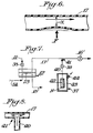
- the control of the pressure on the chamber 20 side of the membrane 23 which provides the variations in pressure can be effected by several means. Representative means are illustrated in Figs. 1, 6, 7 and 8.
- Variations in the pressure in line 17 can be provided as by a combination of the source of pressure 37 and an adjustable clamp as shown in Fig. 1.
- the clamp C pinches the line 17 to provide variability in the line 17.
- this can be used in combination with the pressure on line 17 from the source 37.
- any variable resistance to the flow experienced by the sample liquid on the chamber 20 side of membrane 23 may contribute to the control of the flow across the membrane 23.
- Exerting resistance to flow in the reservoir portion of line 17 varies the pressure differential which is applied at membrane 23. Consequently, the rate of liquid transport through the membrane 23 may be affected by varying a restriction in the tubing through which the liquid passes, as by resistance at C or at P from the source of pressure 37 or both. This mechanism allows fine tuning of the rate of transport through the membrane and, therefore, the extent of dilution.
- Fig. 6 is a sectional view of a portion of line 17 at pressure point F.
- the line 17 has a flexible wall area at pressure point F and thus the tube can be flexed. Flexing the tube 17 inwardly at F forms a narrowed gut X in the interior passage. Flexing the tube 17 outward increases the interior passage.
- FIGs. 7 and 8 Another device for varying the pressure differential between the reservoir portion of line 17 and diluent side of the membrane by restriction of the flow is illustrated in Figs. 7 and 8.
- An air line 40 joins the line 17 in a T-joint 41 and applies air under variable pressure into the line 17 perpendicularly across the axis of flow in line 17.
- a valve 39 is provided in air line 40.
- An enlargement of the T-joint 41 is shown in section in Fig. 8, illustrating the directions of air flow from the pressure source 37. The directional arrows show that the air flow is in both directions at the T-joint 41.
- the air pressure in line 40 can be supplied and controlled by means of an embodiment of the source of pressure 37 as shown in Fig. 7.
- a porous tube 42 in a sealed chamber 43 is attached to the line 40 which extends from the chamber 43 to the T-joint 41. Air (or other driving fluid) is pumped into the chamber under pressure through an inlet 44.
- the porous tube 42 which is sealed at end N provides resistance to flow of the driving fluid.
- the key concept is that a membrane or porous tube serves as a resistance modifying the pressure differential source to a suitable working range.
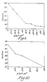
- FIG. 9 An example of a specific application of the apparatus in the dilution of a methyl orange sample liquid is presented in the data set forth in Fig. 9.
- This data was obtained in an apparatus as described herein having a Gore-Tex (trade mark) polytetrafluoroethylene membrane, with a pore size of 0.45 micron and typical porosity of 84%.
- the vacuum pressure in the analysis stream (line 18 in Figure 1) was 27087 N/m2.
- the abcissa indicates the positive pressure applied at point P when valves 16 ⁇ and 38 ( Figure 1) are closed. The pressure is shown in Newtons per square metre on liquid in chamber 20, or the reservoir, and a vacuum on the diluent, or analysis stream, measured at 27087N/m2.
- FIG. 10 A second example is presented in the data of Fig. 10. This data was obtained in an apparatus as described herein have a Gore-Tex (trade mark) membrane of 1 micron pore size and of 91% typical porosity. The system vacuum pressure was 20315 N/m2 for this experiment. Bromothymol blue indicator solution in 0.01 M sodium hydroxide was used to calibrate the diluter assembly 12 and the photodetector 19. The pressure shown on the abscissa is in Newtons per square metre in liquid in chamber 20, or the reservoir, and a vacuum on the diluent or analysis stream measured at 20315 N/m2.
- GORE-TEX registered trademark
- Gore-Tex membrane is an expanded, 100% virgin polytetrafluoroethylene membrane.
- Suitable membranes may be hydrophobically modified Nuclepore (trade mark) polycarbonate or polyester material for processing aqueous solutions, or non-modified polycarbonate or polyester Nuclepore (trade mark) material for use with other solutions.
- membranes which can be provided so as to be impervious and not allow entrance or passage in controllably detectable amounts of suitable selected sample liquids to a diluent stream in the absence of a minimum liquid entry pressure differential.
Landscapes
- Immunology (AREA)
- Pathology (AREA)
- Life Sciences & Earth Sciences (AREA)
- Chemical & Material Sciences (AREA)
- Analytical Chemistry (AREA)
- Biochemistry (AREA)
- Health & Medical Sciences (AREA)
- General Health & Medical Sciences (AREA)
- Physics & Mathematics (AREA)
- General Physics & Mathematics (AREA)
- Sampling And Sample Adjustment (AREA)
- Automatic Analysis And Handling Materials Therefor (AREA)
- Investigating Or Analysing Materials By Optical Means (AREA)
- Nitrogen Condensed Heterocyclic Rings (AREA)
- Pyrrole Compounds (AREA)
- Addition Polymer Or Copolymer, Post-Treatments, Or Chemical Modifications (AREA)
Claims (11)
- Verfahren zur genau gesteuerten Verdünnung von flüssigen Proben in Analysenflüssigkeitsproben, unter Verwendung eines analytischen Detektors zum Messen von Eigenschaften der Flüssigkeit, mit den Schritten:
Vorsehen eines Vorrats (10) von Probenflüssigkeit in Kontakt mit einer Oberfläche einer Poren aufweisenden Membran (23); Vorbeiführen eines Stromes von Verdünnungsmittel (13) über die andere Oberfläche der Membran (23) und durch einen analytischen Detektor (19) zum Analysieren der Probenflüssigkeit; und Anlegen einer Druckdifferenz über die Membran (23), um Mengen der Probenflüsigkeit (10) in den Verdünnungsmittelstrom (13) zu bringen, die für das Detektieren der Probenflüssigkeit durch den analytischen Detektor (19) ausreichen, wobei die Probenflüssigkeit bei Anlegen der Druckdifferenz in dem Verdünnungsmittelstrom verdünnt wird, dadurch gekennzeichnet, daß die über die Membran angelegte Druckdifferenz mindestens gleich einer Mindestdruckdifferenz für den Flüssigkeitseintritt ist, die für das Zuführen einer verdünnten Flüssigkeitsprobe zu dem analytischen Detektor (19) erforderlich ist, und daß die Flüssigkeitsprobe die Membran (23) nicht durchdringt, wenn diese Mindestdruckdifferenz für den Flüssigkeitseintritt nicht angelegt ist. - Verfahren nach Anspruch 1, gekennzeichnet durch den Schritt des Veränderns des Drucks der Probenflüssigkeit in dem Vorrat, um die durch die Membran (23) transportierten Flüssigkeitsmengen zu verändern und zu steuern.
- Verfahren nach Anspruch 1 oder 2, dadurch gekennzeichnet, daß eine Teilmenge der Probenflüssigkeit in einem Behälter gehalten wird, während sie in Kontakt mit der einen Oberfläche der Membran (23) gehalten wird.
- Verfahren nach Anspruch 1, 2 oder 3, dadurch gekennzeichet, daß die Mindestdruckdifferenz für den Flüssigkeitseintritt eine durch Vakuum erzeugte Kraft ist.
- Verfahren nach einem der Ansprüche 1 - 3, dadurch gekennzeichnet, daß die Mindestdruckdifferenz für den Flüssigkeitseintritt eine durch positives Pumpen erzeugte Kraft ist.
- Verfahren nach einem der vorangehenden Ansprüche, dadurch gekennzeichnet, daß der Druck durch ein anderes Fluid aufgebracht wird, wobei die Druckdifferenz durch Verändern eines Strömungswiderstandes des anderen Fluids verändert wird.
- Verfahren zum genau gesteuerten Verdünnen von Flüssigkeitsproben bei der Analyse von Flüssigkeitsproben, mit Zuführmitteln (10, 15) zum Liefern einer Probenflüssigkeit und eines Verdünnungsmittels für die Flüssigkeit; Leitungsmitteln (14) zum Fördern des Verdünnungsmittels in der Vorrichtung, und mit den Leitungsmitteln verbundenen Mitteln (15) zum Anlegen von Druck, um die Flüssigkeit und das Verdünnungsmittel durch die Leitungsmittel zu bewegen; einem Detektor (19) zum Erfassen der Menge der Flüssigkeit in dem Verdünnungsmittel; einem Paar von Kammern (20, 21) in einem Gehäuse (22), die derart angeschlossen sind, daß eine erste Kammer (20) die Probenflüssigkeit enthält und eine zweite Kammer (21) einen Strom des Verdünnungsmittels aufnimmt; einer porösen Membran (23), die in dem Gehäuse zwischen den Kammern angeordnet ist und diese und die darin enthaltene Probenflüssigkeit und Verdünnungsmittel voneinander trennt, und Mitteln (37) zum Anlegen einer Druckdifferenz an die Probenflüssigkeit, dadurch gekennzeichnet, daß die Membran (23) für den Durchgang der Probenflüssigkeit von der ersten Kammer (20) in die zweite Kammer (21) undurchlässig ist, wenn keine Mindestdruckdifferenz für den Flüssigkeitseintritt an die in der ersten Kammer (20) enthaltene Probenflüssigkeit angelegt ist; daß die Mittel (37) für das Anlegen einer Druckdifferenz, die mindestens gleich der Mindestdruckdifferenz für den Flüssigkeitseintritt ist, angepaßt sind, und daß Leitungsmittel (11) für das Fördern der Probenflüssigkeit in der Vorrichtung vorgesehen sind.
- Vorrichtung nach Anspruch 7, gekennzeichnet durch Mittel (C) zum Verändern des an die Probenflüssigkeit in der ersten Kammer (20) angelegten Drucks.
- Vorrichtung nach Anspruch 8, dadurch gekennzeichnet, daß die Leitungsmittel (11, 17) einen flexiblen und kompressiblen Abschnitt aufweisen, um die angelegte Druckdifferenz zu verändern.
- Vorrichtung nach Anspruch 7, 8 oder 9, dadurch gekennzeichnet, daß die Leitungsmittel Leitungen (11, 17) zu und von der Membran (23) und der ersten Kammer (20), sowie Ventile (38, 16') in den Leitungen aufweisen, die betätigbar sind, um zu schließen und Probenflüssigkeit in einem Behälter zu halten, der durch Abschnitte der Leitungen (11, 17) und durch die erste Kammer (20) gebildet ist.
- Vorrichtung nach Anspruch 7, dadurch gekennzeichnet, daß die Leitungsmittel zum Fördern von Probenflüssigkeit einen Behälter aufweisen, aus dem ein Teil der Probenflüssigkeit zwangsgefördert wird.
Priority Applications (1)
| Application Number | Priority Date | Filing Date | Title |
|---|---|---|---|
| AT87307601T ATE90158T1 (de) | 1986-10-14 | 1987-08-27 | Verfahren und geraet zur genau kontrollierten verduennung fluessiger proben. |
Applications Claiming Priority (2)
| Application Number | Priority Date | Filing Date | Title |
|---|---|---|---|
| US91870486A | 1986-10-14 | 1986-10-14 | |
| US918704 | 1986-10-14 |
Publications (3)
| Publication Number | Publication Date |
|---|---|
| EP0264182A2 EP0264182A2 (de) | 1988-04-20 |
| EP0264182A3 EP0264182A3 (en) | 1988-12-07 |
| EP0264182B1 true EP0264182B1 (de) | 1993-06-02 |
Family
ID=25440799
Family Applications (1)
| Application Number | Title | Priority Date | Filing Date |
|---|---|---|---|
| EP87307601A Expired - Lifetime EP0264182B1 (de) | 1986-10-14 | 1987-08-27 | Verfahren und Gerät zur genau kontrollierten Verdünnung flüssiger Proben |
Country Status (11)
| Country | Link |
|---|---|
| EP (1) | EP0264182B1 (de) |
| JP (1) | JPS63184069A (de) |
| AT (1) | ATE90158T1 (de) |
| AU (1) | AU601496B2 (de) |
| CA (1) | CA1309880C (de) |
| DE (1) | DE3786055T2 (de) |
| DK (1) | DK534287A (de) |
| ES (1) | ES2040755T3 (de) |
| FI (1) | FI874513L (de) |
| IL (1) | IL84162A (de) |
| NO (1) | NO874274L (de) |
Families Citing this family (1)
| Publication number | Priority date | Publication date | Assignee | Title |
|---|---|---|---|---|
| DE4411268C2 (de) * | 1994-03-31 | 2001-02-01 | Danfoss As | Analyseverfahren und Analysevorrichtung |
Family Cites Families (8)
| Publication number | Priority date | Publication date | Assignee | Title |
|---|---|---|---|---|
| US3522819A (en) * | 1965-04-23 | 1970-08-04 | Int Minerals & Chem Corp | Apparatus for sampling solids-containing solutions |
| NL7106918A (de) * | 1970-05-20 | 1971-11-23 | ||
| US3833016A (en) * | 1973-01-02 | 1974-09-03 | Meloy Labor Inc | Apparatus for precisely controlled dilution of fluid samples |
| JPS5331794A (en) * | 1976-09-07 | 1978-03-25 | Teijin Ltd | Preparation of polytetramethylene-terephthalate |
| DE2725757A1 (de) * | 1977-06-07 | 1978-12-21 | Fresenius Chem Pharm Ind | Vorrichtung zur fortlaufenden analyse niedermolekularer bestandteile in stroemenden fluessigkeiten |
| AT377493B (de) * | 1979-09-19 | 1985-03-25 | Wiedmer Ernst | Schraubverschluss mit einem garantiering fuer einen behaelter zur anzeige der erstmaligen oeffnung des behaelters |
| SE8102316L (sv) * | 1981-04-10 | 1982-10-11 | Pharmacia Diagnostics Ab | Anordning for genomforande av analyser |
| JPS62153763A (ja) * | 1985-12-27 | 1987-07-08 | Jeol Ltd | 生化学分析装置 |
-
1987
- 1987-08-20 CA CA000544957A patent/CA1309880C/en not_active Expired - Fee Related
- 1987-08-27 EP EP87307601A patent/EP0264182B1/de not_active Expired - Lifetime
- 1987-08-27 AT AT87307601T patent/ATE90158T1/de not_active IP Right Cessation
- 1987-08-27 ES ES198787307601T patent/ES2040755T3/es not_active Expired - Lifetime
- 1987-08-27 DE DE87307601T patent/DE3786055T2/de not_active Expired - Fee Related
- 1987-10-07 AU AU79441/87A patent/AU601496B2/en not_active Ceased
- 1987-10-13 JP JP62256450A patent/JPS63184069A/ja active Pending
- 1987-10-13 FI FI874513A patent/FI874513L/fi not_active IP Right Cessation
- 1987-10-13 NO NO874274A patent/NO874274L/no unknown
- 1987-10-13 DK DK534287A patent/DK534287A/da not_active Application Discontinuation
- 1987-10-13 IL IL84162A patent/IL84162A/xx not_active IP Right Cessation
Also Published As
| Publication number | Publication date |
|---|---|
| EP0264182A3 (en) | 1988-12-07 |
| NO874274D0 (no) | 1987-10-13 |
| DE3786055D1 (de) | 1993-07-08 |
| JPS63184069A (ja) | 1988-07-29 |
| CA1309880C (en) | 1992-11-10 |
| ATE90158T1 (de) | 1993-06-15 |
| ES2040755T3 (es) | 1993-11-01 |
| FI874513A0 (fi) | 1987-10-13 |
| AU7944187A (en) | 1988-04-21 |
| DE3786055T2 (de) | 1993-10-21 |
| EP0264182A2 (de) | 1988-04-20 |
| AU601496B2 (en) | 1990-09-13 |
| NO874274L (no) | 1988-04-15 |
| FI874513A7 (fi) | 1988-04-15 |
| DK534287A (da) | 1988-04-15 |
| IL84162A0 (en) | 1988-03-31 |
| DK534287D0 (da) | 1987-10-13 |
| IL84162A (en) | 1992-03-29 |
| FI874513L (fi) | 1988-04-15 |
Similar Documents
| Publication | Publication Date | Title |
|---|---|---|
| US4920060A (en) | Device and process for mixing a sample and a diluent | |
| CA1214483A (en) | Sample transport system | |
| EP1230028B1 (de) | Verfahren und vorrichtung zur direkten probenahme eines fluids für die mikrofiltration | |
| EP1263533B1 (de) | Mikrofluid-analysekassette | |
| US5739036A (en) | Method for analysis | |
| EP1891413B1 (de) | Doppelprobenkassette und verfahren zur charakterisierung von partikeln in flüssigkeit | |
| JP2790359B2 (ja) | 希釈及び混合用カートリッジ | |
| EP0272044B1 (de) | Diagnostisches Vakuum-Gerät | |
| EP0107631A2 (de) | Integrierte Mikrokanalisation für kontinuierliche Durchflussanalyse | |
| US4958295A (en) | Analyzing apparatus and method for analysis of liquid samples | |
| CA2175228A1 (en) | Apparatus for assaying viscosity changes in fluid samples and method of conducting same | |
| JP2005010165A5 (de) | ||
| US7288195B2 (en) | Method and apparatus for directly sampling a fluid for microfiltration | |
| US4976926A (en) | Vacuum diagnostic device | |
| US20080257071A1 (en) | Microfluidic Device with Porous Membrane and an Unbranched Channel | |
| WO2019168835A1 (en) | Devices and methods for sample analysis with serial dilution | |
| CN102239399A (zh) | 采样设备 | |
| EP0264182B1 (de) | Verfahren und Gerät zur genau kontrollierten Verdünnung flüssiger Proben | |
| CA1306300C (en) | Analyzing apparatus and method for analysis of liquid samples | |
| EP0974053B1 (de) | Detektion von hydrophoben analyten mit niedrigem gehalt in umweltproben | |
| JP3792034B2 (ja) | 粒子分析装置 | |
| EP0762103A1 (de) | Konzentrationsmessvorrichtung |
Legal Events
| Date | Code | Title | Description |
|---|---|---|---|
| PUAI | Public reference made under article 153(3) epc to a published international application that has entered the european phase |
Free format text: ORIGINAL CODE: 0009012 |
|
| AK | Designated contracting states |
Kind code of ref document: A2 Designated state(s): AT BE CH DE ES FR GB IT LI NL SE |
|
| PUAL | Search report despatched |
Free format text: ORIGINAL CODE: 0009013 |
|
| AK | Designated contracting states |
Kind code of ref document: A3 Designated state(s): AT BE CH DE ES FR GB IT LI NL SE |
|
| 17P | Request for examination filed |
Effective date: 19890410 |
|
| 17Q | First examination report despatched |
Effective date: 19901219 |
|
| RTI1 | Title (correction) | ||
| GRAA | (expected) grant |
Free format text: ORIGINAL CODE: 0009210 |
|
| AK | Designated contracting states |
Kind code of ref document: B1 Designated state(s): AT BE CH DE ES FR GB IT LI NL SE |
|
| REF | Corresponds to: |
Ref document number: 90158 Country of ref document: AT Date of ref document: 19930615 Kind code of ref document: T |
|
| ITF | It: translation for a ep patent filed | ||
| REF | Corresponds to: |
Ref document number: 3786055 Country of ref document: DE Date of ref document: 19930708 |
|
| ET | Fr: translation filed | ||
| REG | Reference to a national code |
Ref country code: ES Ref legal event code: FG2A Ref document number: 2040755 Country of ref document: ES Kind code of ref document: T3 |
|
| PLBE | No opposition filed within time limit |
Free format text: ORIGINAL CODE: 0009261 |
|
| STAA | Information on the status of an ep patent application or granted ep patent |
Free format text: STATUS: NO OPPOSITION FILED WITHIN TIME LIMIT |
|
| 26N | No opposition filed | ||
| EAL | Se: european patent in force in sweden |
Ref document number: 87307601.2 |
|
| PGFP | Annual fee paid to national office [announced via postgrant information from national office to epo] |
Ref country code: FR Payment date: 19950809 Year of fee payment: 9 |
|
| PGFP | Annual fee paid to national office [announced via postgrant information from national office to epo] |
Ref country code: AT Payment date: 19950811 Year of fee payment: 9 |
|
| PGFP | Annual fee paid to national office [announced via postgrant information from national office to epo] |
Ref country code: SE Payment date: 19950816 Year of fee payment: 9 Ref country code: GB Payment date: 19950816 Year of fee payment: 9 |
|
| PGFP | Annual fee paid to national office [announced via postgrant information from national office to epo] |
Ref country code: NL Payment date: 19950825 Year of fee payment: 9 |
|
| PGFP | Annual fee paid to national office [announced via postgrant information from national office to epo] |
Ref country code: DE Payment date: 19950828 Year of fee payment: 9 Ref country code: CH Payment date: 19950828 Year of fee payment: 9 |
|
| PGFP | Annual fee paid to national office [announced via postgrant information from national office to epo] |
Ref country code: ES Payment date: 19950830 Year of fee payment: 9 |
|
| PGFP | Annual fee paid to national office [announced via postgrant information from national office to epo] |
Ref country code: BE Payment date: 19951011 Year of fee payment: 9 |
|
| PG25 | Lapsed in a contracting state [announced via postgrant information from national office to epo] |
Ref country code: GB Effective date: 19960827 Ref country code: AT Effective date: 19960827 |
|
| PG25 | Lapsed in a contracting state [announced via postgrant information from national office to epo] |
Ref country code: SE Effective date: 19960828 Ref country code: ES Free format text: THE PATENT HAS BEEN ANNULLED BY A DECISION OF A NATIONAL AUTHORITY Effective date: 19960828 |
|
| PG25 | Lapsed in a contracting state [announced via postgrant information from national office to epo] |
Ref country code: LI Effective date: 19960831 Ref country code: CH Effective date: 19960831 Ref country code: BE Effective date: 19960831 |
|
| BERE | Be: lapsed |
Owner name: HERCULES INC. Effective date: 19960831 |
|
| PG25 | Lapsed in a contracting state [announced via postgrant information from national office to epo] |
Ref country code: NL Effective date: 19970301 |
|
| REG | Reference to a national code |
Ref country code: CH Ref legal event code: PL |
|
| GBPC | Gb: european patent ceased through non-payment of renewal fee |
Effective date: 19960827 |
|
| PG25 | Lapsed in a contracting state [announced via postgrant information from national office to epo] |
Ref country code: FR Effective date: 19970430 |
|
| NLV4 | Nl: lapsed or anulled due to non-payment of the annual fee |
Effective date: 19970301 |
|
| PG25 | Lapsed in a contracting state [announced via postgrant information from national office to epo] |
Ref country code: DE Effective date: 19970501 |
|
| EUG | Se: european patent has lapsed |
Ref document number: 87307601.2 |
|
| REG | Reference to a national code |
Ref country code: FR Ref legal event code: ST |
|
| REG | Reference to a national code |
Ref country code: ES Ref legal event code: FD2A Effective date: 20001204 |
|
| PG25 | Lapsed in a contracting state [announced via postgrant information from national office to epo] |
Ref country code: IT Free format text: LAPSE BECAUSE OF NON-PAYMENT OF DUE FEES Effective date: 20050827 |