EP0264212A2 - Assemblage d'un récipient en plastique - Google Patents
Assemblage d'un récipient en plastique Download PDFInfo
- Publication number
- EP0264212A2 EP0264212A2 EP87308755A EP87308755A EP0264212A2 EP 0264212 A2 EP0264212 A2 EP 0264212A2 EP 87308755 A EP87308755 A EP 87308755A EP 87308755 A EP87308755 A EP 87308755A EP 0264212 A2 EP0264212 A2 EP 0264212A2
- Authority
- EP
- European Patent Office
- Prior art keywords
- wall
- assembly
- peripheral
- closure part
- sealing flange
- Prior art date
- Legal status (The legal status is an assumption and is not a legal conclusion. Google has not performed a legal analysis and makes no representation as to the accuracy of the status listed.)
- Granted
Links
Images


Classifications
-
- B—PERFORMING OPERATIONS; TRANSPORTING
- B29—WORKING OF PLASTICS; WORKING OF SUBSTANCES IN A PLASTIC STATE IN GENERAL
- B29C—SHAPING OR JOINING OF PLASTICS; SHAPING OF MATERIAL IN A PLASTIC STATE, NOT OTHERWISE PROVIDED FOR; AFTER-TREATMENT OF THE SHAPED PRODUCTS, e.g. REPAIRING
- B29C65/00—Joining or sealing of preformed parts, e.g. welding of plastics materials; Apparatus therefor
- B29C65/02—Joining or sealing of preformed parts, e.g. welding of plastics materials; Apparatus therefor by heating, with or without pressure
- B29C65/08—Joining or sealing of preformed parts, e.g. welding of plastics materials; Apparatus therefor by heating, with or without pressure using ultrasonic vibrations
-
- B—PERFORMING OPERATIONS; TRANSPORTING
- B29—WORKING OF PLASTICS; WORKING OF SUBSTANCES IN A PLASTIC STATE IN GENERAL
- B29C—SHAPING OR JOINING OF PLASTICS; SHAPING OF MATERIAL IN A PLASTIC STATE, NOT OTHERWISE PROVIDED FOR; AFTER-TREATMENT OF THE SHAPED PRODUCTS, e.g. REPAIRING
- B29C65/00—Joining or sealing of preformed parts, e.g. welding of plastics materials; Apparatus therefor
- B29C65/56—Joining or sealing of preformed parts, e.g. welding of plastics materials; Apparatus therefor using mechanical means or mechanical connections, e.g. form-fits
- B29C65/58—Snap connection
-
- B—PERFORMING OPERATIONS; TRANSPORTING
- B29—WORKING OF PLASTICS; WORKING OF SUBSTANCES IN A PLASTIC STATE IN GENERAL
- B29C—SHAPING OR JOINING OF PLASTICS; SHAPING OF MATERIAL IN A PLASTIC STATE, NOT OTHERWISE PROVIDED FOR; AFTER-TREATMENT OF THE SHAPED PRODUCTS, e.g. REPAIRING
- B29C65/00—Joining or sealing of preformed parts, e.g. welding of plastics materials; Apparatus therefor
- B29C65/72—Joining or sealing of preformed parts, e.g. welding of plastics materials; Apparatus therefor by combined operations or combined techniques, e.g. welding and stitching
-
- B—PERFORMING OPERATIONS; TRANSPORTING
- B29—WORKING OF PLASTICS; WORKING OF SUBSTANCES IN A PLASTIC STATE IN GENERAL
- B29C—SHAPING OR JOINING OF PLASTICS; SHAPING OF MATERIAL IN A PLASTIC STATE, NOT OTHERWISE PROVIDED FOR; AFTER-TREATMENT OF THE SHAPED PRODUCTS, e.g. REPAIRING
- B29C66/00—General aspects of processes or apparatus for joining preformed parts
- B29C66/01—General aspects dealing with the joint area or with the area to be joined
- B29C66/05—Particular design of joint configurations
- B29C66/10—Particular design of joint configurations particular design of the joint cross-sections
- B29C66/12—Joint cross-sections combining only two joint-segments; Tongue and groove joints; Tenon and mortise joints; Stepped joint cross-sections
- B29C66/124—Tongue and groove joints
- B29C66/1246—Tongue and groove joints characterised by the female part, i.e. the part comprising the groove
- B29C66/12469—Tongue and groove joints characterised by the female part, i.e. the part comprising the groove being asymmetric
-
- B—PERFORMING OPERATIONS; TRANSPORTING
- B29—WORKING OF PLASTICS; WORKING OF SUBSTANCES IN A PLASTIC STATE IN GENERAL
- B29C—SHAPING OR JOINING OF PLASTICS; SHAPING OF MATERIAL IN A PLASTIC STATE, NOT OTHERWISE PROVIDED FOR; AFTER-TREATMENT OF THE SHAPED PRODUCTS, e.g. REPAIRING
- B29C66/00—General aspects of processes or apparatus for joining preformed parts
- B29C66/01—General aspects dealing with the joint area or with the area to be joined
- B29C66/05—Particular design of joint configurations
- B29C66/10—Particular design of joint configurations particular design of the joint cross-sections
- B29C66/12—Joint cross-sections combining only two joint-segments; Tongue and groove joints; Tenon and mortise joints; Stepped joint cross-sections
- B29C66/128—Stepped joint cross-sections
- B29C66/1282—Stepped joint cross-sections comprising at least one overlap joint-segment
-
- B—PERFORMING OPERATIONS; TRANSPORTING
- B29—WORKING OF PLASTICS; WORKING OF SUBSTANCES IN A PLASTIC STATE IN GENERAL
- B29C—SHAPING OR JOINING OF PLASTICS; SHAPING OF MATERIAL IN A PLASTIC STATE, NOT OTHERWISE PROVIDED FOR; AFTER-TREATMENT OF THE SHAPED PRODUCTS, e.g. REPAIRING
- B29C66/00—General aspects of processes or apparatus for joining preformed parts
- B29C66/01—General aspects dealing with the joint area or with the area to be joined
- B29C66/05—Particular design of joint configurations
- B29C66/10—Particular design of joint configurations particular design of the joint cross-sections
- B29C66/12—Joint cross-sections combining only two joint-segments; Tongue and groove joints; Tenon and mortise joints; Stepped joint cross-sections
- B29C66/128—Stepped joint cross-sections
- B29C66/1284—Stepped joint cross-sections comprising at least one butt joint-segment
- B29C66/12841—Stepped joint cross-sections comprising at least one butt joint-segment comprising at least two butt joint-segments
-
- B—PERFORMING OPERATIONS; TRANSPORTING
- B29—WORKING OF PLASTICS; WORKING OF SUBSTANCES IN A PLASTIC STATE IN GENERAL
- B29C—SHAPING OR JOINING OF PLASTICS; SHAPING OF MATERIAL IN A PLASTIC STATE, NOT OTHERWISE PROVIDED FOR; AFTER-TREATMENT OF THE SHAPED PRODUCTS, e.g. REPAIRING
- B29C66/00—General aspects of processes or apparatus for joining preformed parts
- B29C66/01—General aspects dealing with the joint area or with the area to be joined
- B29C66/05—Particular design of joint configurations
- B29C66/302—Particular design of joint configurations the area to be joined comprising melt initiators
- B29C66/3022—Particular design of joint configurations the area to be joined comprising melt initiators said melt initiators being integral with at least one of the parts to be joined
- B29C66/30223—Particular design of joint configurations the area to be joined comprising melt initiators said melt initiators being integral with at least one of the parts to be joined said melt initiators being rib-like
-
- B—PERFORMING OPERATIONS; TRANSPORTING
- B29—WORKING OF PLASTICS; WORKING OF SUBSTANCES IN A PLASTIC STATE IN GENERAL
- B29C—SHAPING OR JOINING OF PLASTICS; SHAPING OF MATERIAL IN A PLASTIC STATE, NOT OTHERWISE PROVIDED FOR; AFTER-TREATMENT OF THE SHAPED PRODUCTS, e.g. REPAIRING
- B29C66/00—General aspects of processes or apparatus for joining preformed parts
- B29C66/50—General aspects of joining tubular articles; General aspects of joining long products, i.e. bars or profiled elements; General aspects of joining single elements to tubular articles, hollow articles or bars; General aspects of joining several hollow-preforms to form hollow or tubular articles
- B29C66/51—Joining tubular articles, profiled elements or bars; Joining single elements to tubular articles, hollow articles or bars; Joining several hollow-preforms to form hollow or tubular articles
- B29C66/54—Joining several hollow-preforms, e.g. half-shells, to form hollow articles, e.g. for making balls, containers; Joining several hollow-preforms, e.g. half-cylinders, to form tubular articles
- B29C66/542—Joining several hollow-preforms, e.g. half-shells, to form hollow articles, e.g. for making balls, containers; Joining several hollow-preforms, e.g. half-cylinders, to form tubular articles joining hollow covers or hollow bottoms to open ends of container bodies
-
- B—PERFORMING OPERATIONS; TRANSPORTING
- B29—WORKING OF PLASTICS; WORKING OF SUBSTANCES IN A PLASTIC STATE IN GENERAL
- B29C—SHAPING OR JOINING OF PLASTICS; SHAPING OF MATERIAL IN A PLASTIC STATE, NOT OTHERWISE PROVIDED FOR; AFTER-TREATMENT OF THE SHAPED PRODUCTS, e.g. REPAIRING
- B29C66/00—General aspects of processes or apparatus for joining preformed parts
- B29C66/50—General aspects of joining tubular articles; General aspects of joining long products, i.e. bars or profiled elements; General aspects of joining single elements to tubular articles, hollow articles or bars; General aspects of joining several hollow-preforms to form hollow or tubular articles
- B29C66/51—Joining tubular articles, profiled elements or bars; Joining single elements to tubular articles, hollow articles or bars; Joining several hollow-preforms to form hollow or tubular articles
- B29C66/54—Joining several hollow-preforms, e.g. half-shells, to form hollow articles, e.g. for making balls, containers; Joining several hollow-preforms, e.g. half-cylinders, to form tubular articles
- B29C66/545—Joining several hollow-preforms, e.g. half-shells, to form hollow articles, e.g. for making balls, containers; Joining several hollow-preforms, e.g. half-cylinders, to form tubular articles one hollow-preform being placed inside the other
-
- B—PERFORMING OPERATIONS; TRANSPORTING
- B29—WORKING OF PLASTICS; WORKING OF SUBSTANCES IN A PLASTIC STATE IN GENERAL
- B29C—SHAPING OR JOINING OF PLASTICS; SHAPING OF MATERIAL IN A PLASTIC STATE, NOT OTHERWISE PROVIDED FOR; AFTER-TREATMENT OF THE SHAPED PRODUCTS, e.g. REPAIRING
- B29C66/00—General aspects of processes or apparatus for joining preformed parts
- B29C66/70—General aspects of processes or apparatus for joining preformed parts characterised by the composition, physical properties or the structure of the material of the parts to be joined; Joining with non-plastics material
- B29C66/71—General aspects of processes or apparatus for joining preformed parts characterised by the composition, physical properties or the structure of the material of the parts to be joined; Joining with non-plastics material characterised by the composition of the plastics material of the parts to be joined
-
- B—PERFORMING OPERATIONS; TRANSPORTING
- B65—CONVEYING; PACKING; STORING; HANDLING THIN OR FILAMENTARY MATERIAL
- B65D—CONTAINERS FOR STORAGE OR TRANSPORT OF ARTICLES OR MATERIALS, e.g. BAGS, BARRELS, BOTTLES, BOXES, CANS, CARTONS, CRATES, DRUMS, JARS, TANKS, HOPPERS, FORWARDING CONTAINERS; ACCESSORIES, CLOSURES, OR FITTINGS THEREFOR; PACKAGING ELEMENTS; PACKAGES
- B65D11/00—Containers having bodies formed by interconnecting or uniting two or more rigid, or substantially rigid, components made wholly or mainly of plastics material
- B65D11/02—Containers having bodies formed by interconnecting or uniting two or more rigid, or substantially rigid, components made wholly or mainly of plastics material of curved cross-section
-
- B—PERFORMING OPERATIONS; TRANSPORTING
- B29—WORKING OF PLASTICS; WORKING OF SUBSTANCES IN A PLASTIC STATE IN GENERAL
- B29C—SHAPING OR JOINING OF PLASTICS; SHAPING OF MATERIAL IN A PLASTIC STATE, NOT OTHERWISE PROVIDED FOR; AFTER-TREATMENT OF THE SHAPED PRODUCTS, e.g. REPAIRING
- B29C66/00—General aspects of processes or apparatus for joining preformed parts
- B29C66/70—General aspects of processes or apparatus for joining preformed parts characterised by the composition, physical properties or the structure of the material of the parts to be joined; Joining with non-plastics material
- B29C66/73—General aspects of processes or apparatus for joining preformed parts characterised by the composition, physical properties or the structure of the material of the parts to be joined; Joining with non-plastics material characterised by the intensive physical properties of the material of the parts to be joined, by the optical properties of the material of the parts to be joined, by the extensive physical properties of the parts to be joined, by the state of the material of the parts to be joined or by the material of the parts to be joined being a thermoplastic or a thermoset
- B29C66/739—General aspects of processes or apparatus for joining preformed parts characterised by the composition, physical properties or the structure of the material of the parts to be joined; Joining with non-plastics material characterised by the intensive physical properties of the material of the parts to be joined, by the optical properties of the material of the parts to be joined, by the extensive physical properties of the parts to be joined, by the state of the material of the parts to be joined or by the material of the parts to be joined being a thermoplastic or a thermoset characterised by the material of the parts to be joined being a thermoplastic or a thermoset
- B29C66/7392—General aspects of processes or apparatus for joining preformed parts characterised by the composition, physical properties or the structure of the material of the parts to be joined; Joining with non-plastics material characterised by the intensive physical properties of the material of the parts to be joined, by the optical properties of the material of the parts to be joined, by the extensive physical properties of the parts to be joined, by the state of the material of the parts to be joined or by the material of the parts to be joined being a thermoplastic or a thermoset characterised by the material of the parts to be joined being a thermoplastic or a thermoset characterised by the material of at least one of the parts being a thermoplastic
- B29C66/73921—General aspects of processes or apparatus for joining preformed parts characterised by the composition, physical properties or the structure of the material of the parts to be joined; Joining with non-plastics material characterised by the intensive physical properties of the material of the parts to be joined, by the optical properties of the material of the parts to be joined, by the extensive physical properties of the parts to be joined, by the state of the material of the parts to be joined or by the material of the parts to be joined being a thermoplastic or a thermoset characterised by the material of the parts to be joined being a thermoplastic or a thermoset characterised by the material of at least one of the parts being a thermoplastic characterised by the materials of both parts being thermoplastics
-
- B—PERFORMING OPERATIONS; TRANSPORTING
- B29—WORKING OF PLASTICS; WORKING OF SUBSTANCES IN A PLASTIC STATE IN GENERAL
- B29C—SHAPING OR JOINING OF PLASTICS; SHAPING OF MATERIAL IN A PLASTIC STATE, NOT OTHERWISE PROVIDED FOR; AFTER-TREATMENT OF THE SHAPED PRODUCTS, e.g. REPAIRING
- B29C66/00—General aspects of processes or apparatus for joining preformed parts
- B29C66/80—General aspects of machine operations or constructions and parts thereof
- B29C66/83—General aspects of machine operations or constructions and parts thereof characterised by the movement of the joining or pressing tools
- B29C66/832—Reciprocating joining or pressing tools
- B29C66/8322—Joining or pressing tools reciprocating along one axis
Definitions
- the present invention relates to a plastics container assembly and is particularly concerned with containers having a base and an upstanding side wall and which are usually generally cylindrical in form and suitable for the marketing and storage of fluid such as paint.
- Paint containers of plastics are well known and are usually discarded when their contents are exhausted. For this reason it is important that the containers should be capable of inexpensive manufacture and of a structure which alleviates leakage of the fluid. This is particularly so where containers are formed as an assembly from a tubular wall and a base which is fitted thereto.
- containers of this latter type can absorb quite severe shock forces, for example if dropped, and in these circumstances it is important for the base to be connected to the side wall in a manner which provides a fluid seal that is likely to be maintained during the application of reasonable shock forces to the container.
- a plastics container assembly having an upstanding side wall and a base and which consists of a tubular wall part and a base closure part filled to a bottom end of the wall part; one of said parts having a peripheral rib and the other part having a peipheral groove within which the rib is received to provide a fluid seal; one of said parts having a peripheral flange which closely overlies a peripheral bottom end face of the other part, and wherein inner surfaces of the wall part and closure part provide a smooth transition from one surface to the other and the effective peripheral junction within the container between the base and the side wall presents a smoothly curved concave profile.
- the present invention it is envisages that a relatively tight fit of the peripheral groove with the rib between the tubular wall part and the base closure part and also between the peripheral flange on one part and the bottom end face of theother part which it overlies will provide an effective seal to retain fluid within the container.
- the tubular wall part will normally be open topped and fitted with a removable lid for storage of, for example, paint.
- the close proximity between the inner surfaces of the wall part and closure part in providing the smooth transition between those surfaces can also serve as a fluid seal.
- the fluid seal which is formed should permit some flexibility between the wall part and closure part to accommodate reasonable shock forces on the container without causing sufficient disruption in all of the seals to permit fluid leakage.
- the peripheral rib is in snap engagement with the groove.
- the wall part and closure part are permanently bonded together, for example by an adhesive or welding.
- This bonding is conveniently achieved between the peripheral flange and the bottom end face which that flange overlies.
- This permanent bonding will provide an additional fluid seal between the closure part and wall part but in the event that the bond is broken, for example by dropping the container onto a corner of its base, an effective fluid seal should be maintained as previously discussed.
- the peripheral flange which may be external and located on the closure part to overlie the bottom end face of the wall part, or may be internal and located on the wall part to overlie a bottom end face of the closure part, may provide a bottom on which the container can stand.
- the base closure part has a flat bottom wall which extends over the bottom of the interior of the container, usually perpendicularly to the side wall of the container, and the peripheral rib and groove engage in the plane of the bottom wall.
- the peripheral rib is located on the tubular wall part with the peripheral groove formed in the closure part in the plane of the bottom wall of that part, in this way efficient usage can be made of the plastics material of the closure part without unnecessarily weakening either the closure part or the tubular wall part.
- the smoothly curved concave profile presented at the effective peripheral junction within the container between the base and the side wall may facilitate complete removal of the container contents for example paint, by brush since it will alleviate paint from becoming trapped in the corner at the bottom of the container (as frequently occurs with conventional paint cans).
- This curved concave profile may be formed by either or both of the inner surfaces of the tubular wall part and the base closure part.
- the closure part may have a tubular extension wall which extends upwardly from a bottom wall of that part within and adjacent to the tubular wall part, preferably so that the upward tubular extension presents the smoothly curved concave profile and is received within a peripheral recess in the tubular wall to provide the smooth transition between the inner surfaces of the wall part and the closure part.
- the tubular wall part may have an internal peripheral sealing flange adjacent to the closure part and which is directed from the side wall downwardly to the closure part so that the sealing flange abuts the closure part to provide a fluid seal, to form the smooth transition between the inner surfaces of the wall part and the closed part and to present at least part of the smoothly curved concave profile.
- the aforementioned peripheral sealing flange may be flexible, for example so that it is displaced by engagement with the closure part during fitting of the closure part to the tubular wall part and the resilence of the plastics material will urge the sealing flange into abutment with the closure part to maintain the fluid seal.
- such a flange may form a peripheral recess beneath it in the tubular wall part so that an upwardly extending tubular extension wall of the closure part is received within the peripheral recess, preferably in complementary manner with the sealing flange overlying the upward extension wall.
- plastics material from which the container of the present invention is constructed will be of a semi-rigid nature such as polypropylen.
- the container assemblies which are partly illustrated have their components moulded in semi-rigid plastics such as polypropylene and are intended to be suitable for use in the storage of paint.
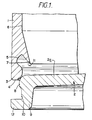
- the assembly comprises a cylindrical tubular side wall 1 and a circular base closure part or end cap 2.
- a bottom end 3 of the wall 1 has a raised annular bead 4, as shown in Figure 1, extending uniformly around the bottom end face. Adjacent the bottom end of the wall 1 is an annular internal groove 5.
- annular internal sealing flange 7 Located adjacent to the groove 5 and on the side of that groove remote from the end 3 (that is above the groove 5) is an annular internal sealing flange 7 which projects downwardly from the inner surface 6 of the side wall towards the bottom end of that wall into which the end cap 2 is to be fitted.
- the sealing flange 7 is tapered so that its thickness reduces uniformally towards its distal edge and this flange has an abutment face 11 which is continuous with the surface of the groove 5.
- the sealing flange 7 In an unstressed condition, as shown in Figure 1, the sealing flange 7 extends generally at an angle in the order of 30° relative to the wall 1 to project over the groove 5.
- the closure cap 2 has a substantially flat bottom wall 2a which will extend in a radial plane of the side wall 1 to close the bottom of the container.
- the cap 2 includes a tubular extension wall 9 which extends downwardly from the closure wall 2a.
- the extension wall 9 has at its lowermost end a radially outwardly extending flange 12 which is intended to overlie the bottom end face of the side wall 1 and provide a bottom surface on which the container will stand.
- Coplanar with the bottom wall 2a on the closure cap is a radially extending annular rib 8 which is intended to be received in the annular groove 5.
- a small external annular recess 10 is provided on the closure cap 2 at the internal corner of the L-shaped section formed between the flange 12 and extension wall 9.
- the closure cap 2 is aligned with the bottom of the cylindrical wall 1 as shown in Figure 1 and pressure applied to force the cap into the wall tube with the annular rib 8 leading.
- the rib 8 of the end cap mover over the lower end of the wall 1 to snap engage in the annular groove 5 as a tight sealing (but not necessarily complementary) fit as shown in Figure 2.
- the face 11 of the sealing flange 7 abuts the inner face of the closure wall 2a and the sealing flange is thereby displaced so that its face 11 is in face-to-face contact with the surface of the bottom wall 2a to provide a fluid seal therewith.
- the flange 12 With the rib 8 engaged in the groove 5, the flange 12 closely overlies the bottom end face formed by the annular bead 4 on the side wall 1.
- the bottom end 3 of the side wall is now permanently bonded to the flange 12 of the closure cap 2 by ultrasonic welding as shown at 3a. During this welding the material formerly creating the bead 4 becomes distributed over the flange 12 and any excess material can be accommodated in the recess 10.
- the bond formed by the weld extends around the entire periphery of the closure cap 2 to provide further sealing between the components.
- welding or other permanent bonding of the flange 12 to the side wall 1 is not essential as the fluid sealing effect of the rib 8 engaging in the groove 5 and also the abutment of the face 11 with the closure wall 2a should be adequate for a relatively viscous fluid such as paint. Also, if the flange 12 closely overlies the bottom face of the wall 1 to abut that face a sealing effect will be provided which will naturally be improved when the container assembly stands on the flange 12 by the load from the side wall 1, (particularly if several filled container assemblies are stacked one above the other).
- annular rib 8 on the closure end cap 2 engages within an annular groove 5 in the side wall 1 but in the embodiments of Figures 3 and 4 the groove and rib are effectively reversed whereby an internal annular rib on the side wall 1 snap-engages with a substantially complementary external annular groove 16 on the bottom closure cap 2.
- the bottom enclosure cap 2 is provided with an upward tubular extension 17 which is located within a complementary recess in the side wall 1.
- the side wall 1 has a peripheral sealing flange 7a which extends downwardly in a similar manner to the flange 7 in Figure 1 so that there is formed beneath the flange 7a and with the adjacent surface of the side wall a peripheral recess 18 which is complementary to the upward extension 17 on the cap 2.
- the sealing flange 7a is in face-to-face abutment with the extension wall 17 while the flange 12 abuts the bottom face of the side wall 1 to provide effective fluid seals.
- the sealing flange 7a again provides the smoothly curved concave profile 13 and the smooth transition at 14 between the inner surfaces of the walls 1 and 2a.
- the upward wall extension 17 of the bottom cap is received in a complementary annular recess or rebate 19 in the inner surface 6 of the wall 1 so that the cylindrical surface 6 of the wall is flush with the inner surface of the extension wall 17 to provide a smooth transition 20 between those surfaces.
- the upward extension wall 17 projects from the bottom closure wall 2a to present a smoothly curved concave profile 21 on the closure cap around the bottom internal corner of the container.
Landscapes
- Engineering & Computer Science (AREA)
- Mechanical Engineering (AREA)
- Closures For Containers (AREA)
Applications Claiming Priority (4)
| Application Number | Priority Date | Filing Date | Title |
|---|---|---|---|
| GB868624533A GB8624533D0 (en) | 1986-10-13 | 1986-10-13 | End cap parts |
| GB8624533 | 1986-10-13 | ||
| GB8702459 | 1987-02-04 | ||
| GB8702459A GB2195973B (en) | 1986-10-13 | 1987-02-04 | A plastics container assembly |
Publications (3)
| Publication Number | Publication Date |
|---|---|
| EP0264212A2 true EP0264212A2 (fr) | 1988-04-20 |
| EP0264212A3 EP0264212A3 (en) | 1989-02-22 |
| EP0264212B1 EP0264212B1 (fr) | 1990-09-19 |
Family
ID=26291415
Family Applications (1)
| Application Number | Title | Priority Date | Filing Date |
|---|---|---|---|
| EP87308755A Expired - Lifetime EP0264212B1 (fr) | 1986-10-13 | 1987-10-02 | Assemblage d'un récipient en plastique |
Country Status (4)
| Country | Link |
|---|---|
| US (1) | US4886181A (fr) |
| EP (1) | EP0264212B1 (fr) |
| AU (1) | AU594511B2 (fr) |
| DE (1) | DE3765076D1 (fr) |
Cited By (4)
| Publication number | Priority date | Publication date | Assignee | Title |
|---|---|---|---|---|
| EP0340949A3 (fr) * | 1988-04-29 | 1990-10-17 | Sonoco Products Company | Boíte en plastique soudée par rotation et méthode pour sa fabrication |
| EP0402166A3 (fr) * | 1989-06-08 | 1991-03-20 | Packaging Innovation Limited | Récipient en matière plastique |
| ITUD20110169A1 (it) * | 2011-10-24 | 2013-04-25 | Luca Saba | Contenitore componibile e scomponibile |
| WO2015132390A1 (fr) * | 2014-03-07 | 2015-09-11 | Polytek Innovations | Procédé et installation de fabrication de capsule |
Families Citing this family (16)
| Publication number | Priority date | Publication date | Assignee | Title |
|---|---|---|---|---|
| DE3904053A1 (de) * | 1989-02-10 | 1990-08-23 | Dillinger Juergen Dipl Finanzw | Baukastensystem |
| US5199593A (en) * | 1990-08-14 | 1993-04-06 | Fuji Photo Film Co., Ltd. | Plastic case having improved ultrasonic welds between halves thereof and method for producing same |
| US5263606A (en) * | 1992-01-17 | 1993-11-23 | Continental Plastics, Inc. | Squeeze container with sonically welded flexible tubular body and bottom cover |
| US5427268A (en) * | 1993-06-16 | 1995-06-27 | Battelle Memorial Institute | Ceramic pressure housing with metal endcaps |
| US5573141A (en) * | 1995-09-11 | 1996-11-12 | Chen; Wen-Yen | Double walled cooling mug |
| US5670108A (en) * | 1995-11-03 | 1997-09-23 | General Motors Corporation | Method of molding a plastic vessel having a flash trap |
| US5855293A (en) * | 1996-09-27 | 1999-01-05 | Automotive Fluid Systems, Inc. | Pressure vessel and method of manufacture thereof |
| US6019240A (en) * | 1997-04-25 | 2000-02-01 | Sst Fiber Drums, Inc. | Fiber board drum with plastic chime assembly |
| EP0943550A3 (fr) * | 1998-03-19 | 1999-11-17 | Frei AG | Fût en métal ayant une fermeture de fond |
| FR2856892B1 (fr) * | 2003-07-04 | 2006-11-17 | Seb Sa | Moule souple rigidifie |
| GB2411893B (en) * | 2004-03-12 | 2007-03-21 | Reckitt Benckiser Healthcare | Packaging for a pharmaceutical product |
| MY151140A (en) * | 2004-09-23 | 2014-04-30 | Petapak Aerosol Internat Corp | Plastic aerosol container and method of manufacturing same |
| US8348088B2 (en) * | 2007-06-22 | 2013-01-08 | Rehrig Pacific Company | Container with reinforced base |
| US20130336710A1 (en) * | 2012-06-14 | 2013-12-19 | Tien-Ming Chou | Plastic Unit |
| EP3758647B1 (fr) * | 2018-02-26 | 2024-07-31 | Argenta Innovation Limited | Dispositif intra-ruminal |
| US11434037B2 (en) * | 2018-08-12 | 2022-09-06 | Amisha Patel | Furan can |
Family Cites Families (16)
| Publication number | Priority date | Publication date | Assignee | Title |
|---|---|---|---|---|
| CH264556A (de) * | 1948-06-30 | 1949-10-31 | Neyer Josef | Verfahren zur Herstellung von Kochtöpfen und nach dem Verfahren hergestellter Kochtopf. |
| FR1098217A (fr) * | 1954-01-14 | 1955-07-20 | Dispositif d'assemblage de deux pièces, plus particulièrement de deux parties constitutives d'un corps creux tel qu'un récipient, dont l'une au moins est en matière élastique | |
| FR1211959A (fr) * | 1958-12-24 | 1960-03-21 | Omni Plastic | Couvercle en matière plastique pour récipients à ouverture conique s'évasant vers le haut |
| US3193132A (en) * | 1963-07-02 | 1965-07-06 | Crouse Hinds Co | Molded plastic box and cover |
| CH432358A (de) * | 1964-10-14 | 1967-03-15 | Hesser Ag Maschf | Verpackungsbehälter, insbesondere für Flüssigkeiten |
| US3843016A (en) * | 1972-08-04 | 1974-10-22 | Thermo Electron Corp | Disposable aspirator |
| BE804759A (nl) * | 1973-09-12 | 1974-01-02 | Verlinden Marius A J | Vat in het bijzonder biervat |
| AU516731B2 (en) * | 1978-03-16 | 1981-06-18 | Polysar Resins, Inc | Sealing of presson lid and container |
| US4355759A (en) * | 1978-04-14 | 1982-10-26 | Automated Container Corporation | Composite container and method |
| US4201306A (en) * | 1978-10-27 | 1980-05-06 | Greif Bros. Corporation | Variable capacity all-plastic drum |
| US4308970A (en) * | 1978-11-27 | 1982-01-05 | Holdt J W Von | Plastic bucket defining annular inwardly projecting ridge |
| AU520832B2 (en) * | 1979-09-10 | 1982-03-04 | Underwood, L. | Container and lid of molded plastic |
| DK549180A (da) * | 1980-12-23 | 1982-06-24 | Nigu Pack As | Baeger eller boetteformet formstofemballage med paatrykningslaag og fremgangsmaade ved paatrykning af laaget |
| GB2163124A (en) * | 1984-06-25 | 1986-02-19 | Vercon Inc | Thermoplastic container end spinwelded to container body |
| DE3428191A1 (de) * | 1984-07-31 | 1986-02-13 | Robert Bosch Gmbh, 7000 Stuttgart | Verfahren zum herstellen eines druckfesten verpackungsbehaelters |
| GB2203135B (en) * | 1987-04-08 | 1990-08-08 | Metal Box Plc | Plug lid for a container |
-
1987
- 1987-10-02 DE DE8787308755T patent/DE3765076D1/de not_active Expired - Lifetime
- 1987-10-02 EP EP87308755A patent/EP0264212B1/fr not_active Expired - Lifetime
- 1987-10-08 AU AU79477/87A patent/AU594511B2/en not_active Ceased
- 1987-10-09 US US07/107,786 patent/US4886181A/en not_active Expired - Fee Related
Cited By (6)
| Publication number | Priority date | Publication date | Assignee | Title |
|---|---|---|---|---|
| EP0340949A3 (fr) * | 1988-04-29 | 1990-10-17 | Sonoco Products Company | Boíte en plastique soudée par rotation et méthode pour sa fabrication |
| EP0402166A3 (fr) * | 1989-06-08 | 1991-03-20 | Packaging Innovation Limited | Récipient en matière plastique |
| ITUD20110169A1 (it) * | 2011-10-24 | 2013-04-25 | Luca Saba | Contenitore componibile e scomponibile |
| WO2015132390A1 (fr) * | 2014-03-07 | 2015-09-11 | Polytek Innovations | Procédé et installation de fabrication de capsule |
| FR3018268A1 (fr) * | 2014-03-07 | 2015-09-11 | Polytek Innovations | Procede et installation de fabrication de capsule |
| US11021279B2 (en) | 2014-03-07 | 2021-06-01 | Melchior Material And Life Science France | Method and installation for the manufacture of capsules |
Also Published As
| Publication number | Publication date |
|---|---|
| EP0264212A3 (en) | 1989-02-22 |
| AU594511B2 (en) | 1990-03-08 |
| EP0264212B1 (fr) | 1990-09-19 |
| AU7947787A (en) | 1988-04-14 |
| US4886181A (en) | 1989-12-12 |
| DE3765076D1 (de) | 1990-10-25 |
Similar Documents
| Publication | Publication Date | Title |
|---|---|---|
| EP0264212B1 (fr) | Assemblage d'un récipient en plastique | |
| US4004710A (en) | Container and closure therefor | |
| US4079857A (en) | Containers and closures | |
| US4887735A (en) | Container | |
| US9079694B2 (en) | Self sealing bag in box cap assembly | |
| US6439429B1 (en) | Tamper-evident closure and spout fitment for a pouch | |
| US4736870A (en) | Powder proof reclosable container | |
| US4529100A (en) | Container and sealed closure means | |
| US4434907A (en) | Container having an originally sealed condition which can be opened and thereafter closed | |
| US5667089A (en) | Closure having a wrap-around seal | |
| US3734393A (en) | Wide mouth tubular container construction | |
| US4620642A (en) | Resilient plug closure | |
| CA1127597A (fr) | Bec verseur refermable pour contenants | |
| IE64405B1 (en) | Plastics cap for blow-moulded plastics containers | |
| JP2004509817A (ja) | 容器の閉塞構造 | |
| US4856708A (en) | Adhesively secured container cover | |
| US4846366A (en) | Container and closure | |
| GB2195973A (en) | Container end closure | |
| EP0960055B1 (fr) | Recipient a couvercle pour contenir un milieu fluide | |
| US4427128A (en) | Can and closure therefor | |
| GB2111470A (en) | Containers | |
| JPH08198290A (ja) | 容 器 | |
| AU2010100923A4 (en) | Lid locking ring | |
| JPH03162252A (ja) | 密閉容器 | |
| JPH0420762Y2 (fr) |
Legal Events
| Date | Code | Title | Description |
|---|---|---|---|
| PUAI | Public reference made under article 153(3) epc to a published international application that has entered the european phase |
Free format text: ORIGINAL CODE: 0009012 |
|
| AK | Designated contracting states |
Kind code of ref document: A2 Designated state(s): BE CH DE FR GB IT LI NL |
|
| PUAL | Search report despatched |
Free format text: ORIGINAL CODE: 0009013 |
|
| AK | Designated contracting states |
Kind code of ref document: A3 Designated state(s): BE CH DE FR GB IT LI NL |
|
| RHK1 | Main classification (correction) |
Ipc: B65D 8/04 |
|
| 17P | Request for examination filed |
Effective date: 19890222 |
|
| 17Q | First examination report despatched |
Effective date: 19890626 |
|
| GRAA | (expected) grant |
Free format text: ORIGINAL CODE: 0009210 |
|
| AK | Designated contracting states |
Kind code of ref document: B1 Designated state(s): BE CH DE FR GB IT LI NL |
|
| ITF | It: translation for a ep patent filed | ||
| PGFP | Annual fee paid to national office [announced via postgrant information from national office to epo] |
Ref country code: FR Payment date: 19901024 Year of fee payment: 4 |
|
| REF | Corresponds to: |
Ref document number: 3765076 Country of ref document: DE Date of ref document: 19901025 |
|
| ET | Fr: translation filed | ||
| PGFP | Annual fee paid to national office [announced via postgrant information from national office to epo] |
Ref country code: NL Payment date: 19901031 Year of fee payment: 4 |
|
| PGFP | Annual fee paid to national office [announced via postgrant information from national office to epo] |
Ref country code: CH Payment date: 19901102 Year of fee payment: 4 |
|
| PGFP | Annual fee paid to national office [announced via postgrant information from national office to epo] |
Ref country code: BE Payment date: 19901129 Year of fee payment: 4 |
|
| PGFP | Annual fee paid to national office [announced via postgrant information from national office to epo] |
Ref country code: DE Payment date: 19901130 Year of fee payment: 4 |
|
| PLBE | No opposition filed within time limit |
Free format text: ORIGINAL CODE: 0009261 |
|
| STAA | Information on the status of an ep patent application or granted ep patent |
Free format text: STATUS: NO OPPOSITION FILED WITHIN TIME LIMIT |
|
| 26N | No opposition filed | ||
| ITTA | It: last paid annual fee | ||
| PG25 | Lapsed in a contracting state [announced via postgrant information from national office to epo] |
Ref country code: LI Effective date: 19911031 Ref country code: CH Effective date: 19911031 Ref country code: BE Effective date: 19911031 |
|
| BERE | Be: lapsed |
Owner name: LIN PAC MOULDINGS LTD Effective date: 19911031 |
|
| PG25 | Lapsed in a contracting state [announced via postgrant information from national office to epo] |
Ref country code: NL Effective date: 19920501 |
|
| NLV4 | Nl: lapsed or anulled due to non-payment of the annual fee | ||
| PG25 | Lapsed in a contracting state [announced via postgrant information from national office to epo] |
Ref country code: FR Effective date: 19920630 |
|
| REG | Reference to a national code |
Ref country code: CH Ref legal event code: PL |
|
| PG25 | Lapsed in a contracting state [announced via postgrant information from national office to epo] |
Ref country code: DE Effective date: 19920701 |
|
| REG | Reference to a national code |
Ref country code: FR Ref legal event code: ST |
|
| REG | Reference to a national code |
Ref country code: GB Ref legal event code: 732E |
|
| PGFP | Annual fee paid to national office [announced via postgrant information from national office to epo] |
Ref country code: GB Payment date: 19990930 Year of fee payment: 13 |
|
| PG25 | Lapsed in a contracting state [announced via postgrant information from national office to epo] |
Ref country code: GB Free format text: LAPSE BECAUSE OF NON-PAYMENT OF DUE FEES Effective date: 20001002 |
|
| GBPC | Gb: european patent ceased through non-payment of renewal fee |
Effective date: 20001002 |
|
| PG25 | Lapsed in a contracting state [announced via postgrant information from national office to epo] |
Ref country code: IT Free format text: LAPSE BECAUSE OF NON-PAYMENT OF DUE FEES;WARNING: LAPSES OF ITALIAN PATENTS WITH EFFECTIVE DATE BEFORE 2007 MAY HAVE OCCURRED AT ANY TIME BEFORE 2007. THE CORRECT EFFECTIVE DATE MAY BE DIFFERENT FROM THE ONE RECORDED. Effective date: 20051002 |