EP0264236A2 - Procédé de test de fidélité d'un système de mesure rhéologique - Google Patents
Procédé de test de fidélité d'un système de mesure rhéologique Download PDFInfo
- Publication number
- EP0264236A2 EP0264236A2 EP87308958A EP87308958A EP0264236A2 EP 0264236 A2 EP0264236 A2 EP 0264236A2 EP 87308958 A EP87308958 A EP 87308958A EP 87308958 A EP87308958 A EP 87308958A EP 0264236 A2 EP0264236 A2 EP 0264236A2
- Authority
- EP
- European Patent Office
- Prior art keywords
- power shaft
- transducer
- test chamber
- repeatability
- rheologic
- Prior art date
- Legal status (The legal status is an assumption and is not a legal conclusion. Google has not performed a legal analysis and makes no representation as to the accuracy of the status listed.)
- Ceased
Links
Images

Classifications
-
- G—PHYSICS
- G01—MEASURING; TESTING
- G01N—INVESTIGATING OR ANALYSING MATERIALS BY DETERMINING THEIR CHEMICAL OR PHYSICAL PROPERTIES
- G01N11/00—Investigating flow properties of materials, e.g. viscosity, plasticity; Analysing materials by determining flow properties
-
- G—PHYSICS
- G01—MEASURING; TESTING
- G01N—INVESTIGATING OR ANALYSING MATERIALS BY DETERMINING THEIR CHEMICAL OR PHYSICAL PROPERTIES
- G01N11/00—Investigating flow properties of materials, e.g. viscosity, plasticity; Analysing materials by determining flow properties
- G01N11/10—Investigating flow properties of materials, e.g. viscosity, plasticity; Analysing materials by determining flow properties by moving a body within the material
- G01N11/14—Investigating flow properties of materials, e.g. viscosity, plasticity; Analysing materials by determining flow properties by moving a body within the material by using rotary bodies, e.g. vane
Definitions
- This invention relates to a method of testing repeatability of a rheologic system.
- the present inventive method makes usage of a strain transducer.
- Strain transducers as such, have long been known in the prior art. However, their usage in the method as set forth herein is believed to be novel.
- the above and other prior art is not capable of measuring or responding to all components which are torsionally imparted to the power shaft within the test vessel. More particularly, the prior art does not teach a test method which measures or utilizes both the radial and axial components of torque in the test vessel.
- the present invention comprises a method for testing the repeatability of the output of a rheological instrument, said instrument having a power shaft and a test chamber.
- the method comprises the step of using a circumferentially oriented torque transducer to re-iteratively compare the reactive torque imparted to said power shaft by use of rheological reference samples and comparing the reactive torques thereof. Differences between reactive torques from identical reference samples will indicate a need to appropriately calibrate the test instrument before field usage thereof is made.
- the method according to the present invention preferably provides a method and means for simply, conveniently, and cost-effectively determining the repeatability and, thereby, correctness of calibration of a test instrument employing a power shaft as an element thereof.
- the method according to the present invention for testing the repeatability of the output of instruments is employed in measuring the viscosity of the liquid phase of normally solid materials such as polymers.
- the present inventive method may be viewed as a method for testing or calibrating an analytic test system.
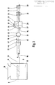
- the mixing apparatus 8 which includes the test chamber 12, a hopper 25, the power shaft 10, and a spiral mixing element 15 by which resin pellet or other test materials are selectively dropped into hopper 25 for purposes of mixing within test chamber 12 by virtue of the rotation of the said mixing element.
- such mixing occurs at a pre-determined temperature and is subject to a pre-determined torque from power shaft 10.
- This torque may be considered in terms of axial and radial components which are imparted to the lattice structure of the material placed into chamber 12.
- said pellets are elevated in temperature such that the resin, or other test material, is in its liquid phase during the interval of rotation of power shaft 10 and the mixing element 15.
- spiral (or screw-like) mixing element 15 accomplishes, by virtue of its special geometry, a summing of the axial and radial components of the reactive torque imparted from the test material. This reactive torque is then torsionally transmitted through said power shaft 10 to a spirally-wound transducer 14 (further described below).
- power shaft 10 is provided with an output coupling 26.
- a driver coupling plate 44 To said output coupling 26, and in alignment with the axis of rotation 16 of power shaft 10, is provided a driver coupling plate 44.
- This element is, in turn, mechanically mated to a driver coupling plate 42 which includes a shear pin 40.
- Said coupling plate 42 is axially secured to male element 21 through key 19 and shear pinhole 41 (See also Fig. 3).
- Male element 21 is integral with linkage 23 about which is spirally wound said transducer means 14 which, in a preferred embodiment, is a torsional strain gauge in the nature of a piezoelectric element.
- a piezoelectric element by definition, generates an analog electrical output as a direct and, within a given range, linear output of an input of mechanical pressure.
- the input is in the nature of spiral torque torsionally imparted to transducer 14 from spiral mixing element 15 through the rotation of power shaft 10 in test chamber 12.
- transducer 14 in the manner shown in Figs. 1 and 3, is significant in that it will serve to measure the integrated total of the axial and radial components of reactive torque from the test sample imparted to the mixing element 15 and power shaft 10.
- the output of the transducer 14 is compared with respective rheologic reference material samples, an accurate determination can be made as to whether a large microprocessor-controlled torque rheometer system is operating properly.
- the present method of testing the output of the rheologic measuring instrument comprises a quality-control, calibration, and self-check means through which variations of floats in measurements from the microprocessor system can be ascertained before any production use of the material mixed within chamber 12 is made.
- transducer 14 is electrically connected by wire 17 to analog-to-digital connector/convertor 30. Thereafter, the converter digital signal passes, by wire 29, thru the power shaft 10, through slip rings 20, and to voltage output 22 of the system.
- FIG. 3 and 4 The central mechanical interface of the system is shown in Figs. 3 and 4 in which linkage 23 is seen to connect to a male output hub 27 associated with the transducer 14 and its linkage 23. Therein, male hub 27 mates with female hub 28 through driving pin 38. Further shown at the connection between hubs 27 and 28 are respective male and female electrical fuses 34 and 36, the function of which is to generate an abort or interrupt signal to the system if the transducer 14 senses an excessive output across connector 30.
- the present invention is to be understood as a method for testing the repeatability of an output of a rheological measuring system.
- the method comprises the step of using the torque transducer 14 to re-iteratively compare the reactive torques imparted to said power shaft through the use of the respective rheological reference material samples and then comparing the reactive torques thereof.
- differences in the comparative reactive torques measured by said torque transducer will indicate, if such is the case, any lack of repeatability in sequential outputs of the rheological measuring system.
- the inventive method may be seen as comprising the steps of mechanically coupling said transducer 14, exteriorly of said test chambers, to a point on the axis of rotation 16 of power shaft 10. Thereafter, test chamber 12 is filled with the sample material of a pre-defined quantity and rheological characteristic, while maintaining the same material at a pre-determined temperature. As a further step, the system is operated for a fixed duration. Thereafter, the digital output of transducer 14 is measured and recorded.
- test chamber 12 must be completely emptied and cleaned. Thereafter, and prior to the next contemplated usage of a "recipe" employing said sample material, the said steps of operating the system for a fixed period of time, and measuring and recording the electrical output of said transducer are repeated. Thereafter, data generated by said repetition step and the first taking of the same data are compared. Thereby, differences in measurements recorded between the recorded torque outputs of the same rheologic reference samples will indicate the existence or absence of repeatability of the rheological measurement system. If lack of repeatability is found, there will, of course, be a need for recalibration of the test system. Further, external testing of the transducer is desirable for purposes of completeness.
- Fig. 2 the rest of the system is shown schematically. This includes male and female hubs 27 and 28 which are operated by the gear box 18 which, in turn, is powered by right angle wormdrive 32 and AC motor 24.
Landscapes
- Physics & Mathematics (AREA)
- Health & Medical Sciences (AREA)
- Life Sciences & Earth Sciences (AREA)
- Chemical & Material Sciences (AREA)
- Analytical Chemistry (AREA)
- Biochemistry (AREA)
- General Health & Medical Sciences (AREA)
- General Physics & Mathematics (AREA)
- Immunology (AREA)
- Pathology (AREA)
- Investigating Strength Of Materials By Application Of Mechanical Stress (AREA)
- Testing Of Devices, Machine Parts, Or Other Structures Thereof (AREA)
Applications Claiming Priority (4)
| Application Number | Priority Date | Filing Date | Title |
|---|---|---|---|
| US91761986A | 1986-10-10 | 1986-10-10 | |
| US917619 | 1986-10-10 | ||
| US8840487A | 1987-08-24 | 1987-08-24 | |
| US88404 | 1987-08-24 |
Publications (2)
| Publication Number | Publication Date |
|---|---|
| EP0264236A2 true EP0264236A2 (fr) | 1988-04-20 |
| EP0264236A3 EP0264236A3 (fr) | 1988-10-05 |
Family
ID=26778619
Family Applications (1)
| Application Number | Title | Priority Date | Filing Date |
|---|---|---|---|
| EP87308958A Ceased EP0264236A3 (fr) | 1986-10-10 | 1987-10-09 | Procédé de test de fidélité d'un système de mesure rhéologique |
Country Status (4)
| Country | Link |
|---|---|
| EP (1) | EP0264236A3 (fr) |
| JP (1) | JPS6457146A (fr) |
| KR (1) | KR900005218B1 (fr) |
| CN (1) | CN1012526B (fr) |
Cited By (2)
| Publication number | Priority date | Publication date | Assignee | Title |
|---|---|---|---|---|
| CN1036613C (zh) * | 1994-04-23 | 1997-12-03 | 山东省淄川区电子工业设备厂 | 旋转粘度计 |
| CN101387595B (zh) * | 2007-09-14 | 2011-04-20 | 中航惠腾风电设备股份有限公司 | 全自动凝胶试验机及其应用 |
Families Citing this family (2)
| Publication number | Priority date | Publication date | Assignee | Title |
|---|---|---|---|---|
| KR100877494B1 (ko) * | 2007-01-25 | 2009-01-09 | 재단법인서울대학교산학협력재단 | 혼합유동 레오미터 |
| CN113776988A (zh) * | 2020-06-10 | 2021-12-10 | Vmi荷兰公司 | 用于确定粘性聚合物质的流变性质的测量装置和方法 |
Family Cites Families (5)
| Publication number | Priority date | Publication date | Assignee | Title |
|---|---|---|---|---|
| US2873584A (en) * | 1954-12-02 | 1959-02-17 | Phillips Petroleum Co | Contactor and torque control device |
| US3675470A (en) * | 1970-04-24 | 1972-07-11 | Rion Co | Viscometer |
| US4145921A (en) * | 1978-01-24 | 1979-03-27 | University Of Southern California | Vorticity probe utilizing strain measurements |
| US4445365A (en) * | 1982-05-17 | 1984-05-01 | Selby Theodore W | Tapered bearing simulator-viscometer |
| US4501155A (en) * | 1983-06-29 | 1985-02-26 | Rheometrics, Inc. | Compensated rheometer |
-
1987
- 1987-09-30 CN CN87106727A patent/CN1012526B/zh not_active Expired
- 1987-10-09 EP EP87308958A patent/EP0264236A3/fr not_active Ceased
- 1987-10-10 KR KR1019870011236A patent/KR900005218B1/ko not_active Expired
- 1987-10-12 JP JP62257058A patent/JPS6457146A/ja active Pending
Cited By (2)
| Publication number | Priority date | Publication date | Assignee | Title |
|---|---|---|---|---|
| CN1036613C (zh) * | 1994-04-23 | 1997-12-03 | 山东省淄川区电子工业设备厂 | 旋转粘度计 |
| CN101387595B (zh) * | 2007-09-14 | 2011-04-20 | 中航惠腾风电设备股份有限公司 | 全自动凝胶试验机及其应用 |
Also Published As
| Publication number | Publication date |
|---|---|
| CN1012526B (zh) | 1991-05-01 |
| EP0264236A3 (fr) | 1988-10-05 |
| JPS6457146A (en) | 1989-03-03 |
| KR900005218B1 (ko) | 1990-07-21 |
| KR880005449A (ko) | 1988-06-29 |
| CN87106727A (zh) | 1988-05-04 |
Similar Documents
| Publication | Publication Date | Title |
|---|---|---|
| US4594883A (en) | Monitoring physical properties of a fluid | |
| US7526941B2 (en) | Rheometer torque calibration fixture | |
| JP3220189B2 (ja) | 物質の基本粘弾特性を測定する方法及びその装置 | |
| US5325716A (en) | Apparatus for determining the pressure distribution along a limited distance and method for manufacturing it | |
| US11719612B2 (en) | Rotor for rheological measurements of material with variable volume | |
| CA2084114A1 (fr) | Rheometre et methode de fonctionnement | |
| CN101498575A (zh) | 用于测量转动叶片上的应力的装置及方法 | |
| EP0264236A2 (fr) | Procédé de test de fidélité d'un système de mesure rhéologique | |
| US4930346A (en) | Method for the determination of the properties of mouldable materials, particularly for the determination of the plastic and reologic properties thereof | |
| JPH0349616B2 (fr) | ||
| EP2063249A2 (fr) | Fixation de rhéomètre | |
| US4899576A (en) | Method for testing repeatability of a rheologic system | |
| SU1718736A3 (ru) | Устройство дл измерени давлени массы в двухшнековом экструдере | |
| GB2025070A (en) | Method of determining characteristic rheological quantities of viscoelastic materials | |
| US3965722A (en) | Apparatus for the measurement of viscosity | |
| US11781961B1 (en) | Method and device for monitoring transformation processes of fluids | |
| US3128620A (en) | Torque tube rotational viscometer | |
| CN211696746U (zh) | 一种非密封电阻温度传感器精度测试装置 | |
| US4827768A (en) | Motor-driven material level indicator | |
| CN114813475B (zh) | 一种判断固体推进剂固化反应终点的方法 | |
| US3116631A (en) | Apparatus for measuring viscosity of thermoplastics | |
| EP0671623B1 (fr) | Appareil de mesure de l'humidité de grains et semblables | |
| SU1132200A1 (ru) | Устройство дл определени пластичности и скорости отверждени пластических масс | |
| SU697881A1 (ru) | Вискозиметр | |
| JP2001174391A (ja) | ゲル化時間測定装置 |
Legal Events
| Date | Code | Title | Description |
|---|---|---|---|
| PUAI | Public reference made under article 153(3) epc to a published international application that has entered the european phase |
Free format text: ORIGINAL CODE: 0009012 |
|
| AK | Designated contracting states |
Kind code of ref document: A2 Designated state(s): AT BE CH DE ES FR GB GR IT LI LU NL SE |
|
| RIN1 | Information on inventor provided before grant (corrected) |
Inventor name: HECTUS, GEORGE V. Inventor name: NOVEMBER, DANIEL Inventor name: LANGLEY, WILLIAM EDWARD Inventor name: DARNOPUK, HARRY |
|
| RAP1 | Party data changed (applicant data changed or rights of an application transferred) |
Owner name: HAAKE-BUCHLER INSTRUMENTS, INC. |
|
| PUAL | Search report despatched |
Free format text: ORIGINAL CODE: 0009013 |
|
| AK | Designated contracting states |
Kind code of ref document: A3 Designated state(s): AT BE CH DE ES FR GB GR IT LI LU NL SE |
|
| 17P | Request for examination filed |
Effective date: 19890405 |
|
| 17Q | First examination report despatched |
Effective date: 19890929 |
|
| STAA | Information on the status of an ep patent application or granted ep patent |
Free format text: STATUS: THE APPLICATION HAS BEEN REFUSED |
|
| 18R | Application refused |
Effective date: 19910913 |
|
| RIN1 | Information on inventor provided before grant (corrected) |
Inventor name: HECTUS, GEORGE V. Inventor name: DARNOPUK, HARRY Inventor name: LANGLEY, WILLIAM EDWARD Inventor name: NOVEMBER, DANIEL |