EP0264246B1 - Reinigungsvorrichtung für einen Behälter - Google Patents
Reinigungsvorrichtung für einen Behälter Download PDFInfo
- Publication number
- EP0264246B1 EP0264246B1 EP87309001A EP87309001A EP0264246B1 EP 0264246 B1 EP0264246 B1 EP 0264246B1 EP 87309001 A EP87309001 A EP 87309001A EP 87309001 A EP87309001 A EP 87309001A EP 0264246 B1 EP0264246 B1 EP 0264246B1
- Authority
- EP
- European Patent Office
- Prior art keywords
- cleaning
- container
- cleaning device
- base
- pillars
- Prior art date
- Legal status (The legal status is an assumption and is not a legal conclusion. Google has not performed a legal analysis and makes no representation as to the accuracy of the status listed.)
- Expired
Links
- 238000004140 cleaning Methods 0.000 title claims description 143
- 239000011521 glass Substances 0.000 claims description 26
- 239000000463 material Substances 0.000 claims description 4
- 239000004033 plastic Substances 0.000 claims description 4
- 230000003014 reinforcing effect Effects 0.000 claims description 3
- 229910052751 metal Inorganic materials 0.000 claims 1
- 239000002184 metal Substances 0.000 claims 1
- 150000002739 metals Chemical class 0.000 claims 1
- 239000003599 detergent Substances 0.000 description 5
- 238000004851 dishwashing Methods 0.000 description 4
- 230000004048 modification Effects 0.000 description 4
- 238000012986 modification Methods 0.000 description 4
- 239000007788 liquid Substances 0.000 description 3
- 239000000853 adhesive Substances 0.000 description 2
- 230000001070 adhesive effect Effects 0.000 description 2
- 238000000926 separation method Methods 0.000 description 2
- 239000012141 concentrate Substances 0.000 description 1
- 239000013013 elastic material Substances 0.000 description 1
- 239000004744 fabric Substances 0.000 description 1
- 238000001746 injection moulding Methods 0.000 description 1
- 238000003780 insertion Methods 0.000 description 1
- 230000037431 insertion Effects 0.000 description 1
- 238000000034 method Methods 0.000 description 1
- 238000005498 polishing Methods 0.000 description 1
- 230000002035 prolonged effect Effects 0.000 description 1
- 239000012858 resilient material Substances 0.000 description 1
Images


Classifications
-
- A—HUMAN NECESSITIES
- A47—FURNITURE; DOMESTIC ARTICLES OR APPLIANCES; COFFEE MILLS; SPICE MILLS; SUCTION CLEANERS IN GENERAL
- A47L—DOMESTIC WASHING OR CLEANING; SUCTION CLEANERS IN GENERAL
- A47L17/00—Apparatus or implements used in manual washing or cleaning of crockery, table-ware, cooking-ware or the like
Definitions
- the present invention generally relates to cleaning devices and more particularly to a cleaning device for cleaning inner and outer surfaces of a container such as a glass by a single cleaning step.
- a container such as a glass is cleaned by human hand.
- the container is held by one hand of a person doing the cleaning; and inner and outer surfaces of the container are cleaned by a cleaning body such as a sponge cleaner held by another hand of the person.
- a cleaning body which is permanently or removably fixed to a sink, see for instance DE-U 1 992 137 or GB-A 2 154 127 or US-A 975 862.
- a cleaning body which is permanently or removably fixed to a sink, see for instance DE-U 1 992 137 or GB-A 2 154 127 or US-A 975 862.
- a cleaning body which is permanently or removably fixed to a sink
- a dish washing machine is sometimes used.
- a container, particularly a glass, cleaned by such a dish washing machine tend to show spots of detergent on the surface of the container when the container is dried.
- This polishing operation can only be performed by human hand. Therefore, one cannot avoid the similar problems associated with the cleaning by human hand even if one uses a dish washing machine.
- the glasses cleaned by the dish washing machine tend to be chipped or cracked due to the vibration of the machine. This increases the risk of the person being injured during the removal of the spots of detergent.
- a U-shaped cleaning device for cleaning the container is also known in which a wall of the container is held between a pair of legs of the device arranged in a U-shaped configuration. The container is rotated in this state and the container is cleaned by the cleaning bodies carried by the legs of the device.
- a U-shaped cleaning device has a problem in that the cleaning of the outer surface of the container becomes incomplete when one rotates the container while pressing the container against one of the legs to clean the inner surface.
- the cleaning of the inner surface becomes incomplete when one rotates the container while pressing the container against another leg to clean the outer surface.
- Another and more specific object of the present invention is to provide a cleaning device of a container such as a glass comprising first and second pillars standing from a base in a generally vertical direction from the base and respectively extending along a contour of inner and outer surfaces of the container to be cleaned, first and second cleaning bodies respectively carried by the first and second pillars for cleaning the inner surface and outer surface of the container, and a third pillar standing from a portion of the base at a vicinity of the first cleaning body in a generally vertical direction and extending along the first cleaning body, in which the first pillar supports the inner surface of a first wall portion of the container mounted on the device for cleaning with the first cleaning body carried by the first pillar intervening between the first pillar and the inner surface, the second pillar supports the outer surface of a second wall portion of the container diametrically opposing to the first wall portion with the second cleaning body intervening between the second pillar and the outer surface, the third pillar presses the outer surface of the first wall portion of the container toward the direction of the first pillar so as to urge
- the container is supported in a stable manner by the first, second and third pillars as it is rotated for cleaning and the inner surface and the outer surface of the container is cleaned by the rubbing action of the first and second cleaning bodies in a single step of operation. Further, the need for urging the container toward the direction of the first and second pillars during the rotation is eliminated.
- the device according to the present invention is easy to use and the danger of damaging the container is minimized. The risk of the working person being injured is also minimized accordingly, and the efficiency of the cleaning work is improved. Further, the cleaning device according to the present invention is simple and easily manufactured with little cost.
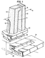
- FIG.1 is a perspective view showing a first embodiment of the cleaning device according to the present invention.
- the cleaning device comprises a first and second resilient pillars 11 and 12 standing from a base 10 in a generally vertical direction to the base and extending along a contour of an inner surface (including a bottom) and an outer surface of a container 16 such as a glass or a plastic cup to be cleaned (not shown in FIG.1).
- the pillars 11 and 12 hold on one side first and second elastically deformable cleaning bodies 13 and 14 which contact with the inner and outer surfaces of the container 16 and clean these surfaces.
- the cleaning bodies are formed from a soft and porous elastic material such as a sponge rubber and the like and absorb a cleaning liquid containing a detergent.
- such cleaning bodies cover one side of the surface of the pillars 11 and 12 completely and extend continuously along the contour of the inner and outer surfaces of the container. Further, a tip of the pillar 11 is bent toward the direction of the pillar 12 at a position generally corresponding to the tip of the pillar 12 along the contour of the container 16.
- the container 16 is a glass having a shape of a truncated cone.
- the bent portion of the pillar 11 supports a bottom of the glass by the cleaning body 13.
- the pillars 11 and 12 has a sufficient length such as 10 - 20 cm depending on the depth of the glass.
- the pillars 11 and 12 also have a width of several centimeters, for example, sufficient for supporting the inner and outer surface of the container 16 in a stable manner when the glass is rotated for cleaning.
- a third resilient pillar 15 stands from the base 10 adjacent to the first cleaning body 13 supporting the inner surface of the container 16 and extends along the cleaning body 13.
- the pillar 15 extends along the pillar 11 carrying the cleaning body 13.
- the pillars 11, 12 and 15 are made of plastic material having a sufficient resiliency. Further, it is most advantageous to produce the pillars 11, 12 and 15 together with the base 10 as an integral body by injection molding and the like. The pillar 15 extends for an appropriate distance from the base 10 and the tip of the pillar 15 is curved towards direction away from the cleaning body 13.
- a structure 22 at a bottom surface of the base 10 for mounting the base 10 to a mount 21 fixed on a wall 20 in the vicinity of a sink (not shown).
- the structure 22 is shown as a rail slideably engages with a corresponding groove in the mount 21.
- the structure is not limited to such a rail but any known structures such as a suction pad may be used instead.
- the mount 21 may be fixed on the wall 20 by well known means such as adhesives or screws.
- ribs 31 and 32 may be provided on the pillars 11 and 12 (FIG.2) according to the need.
- each of the pillars 11, 12 and 15 there are only one each of the pillars 11, 12 and 15.
- the number of the pillars are not limited to one but a plurality of pillars may be used for pillar 11, 12 and 15 according to the size and shape of the container to be cleaned. It is to be understood that such modifications are included within the scope of the present invention.
- FIG.2 is a cross sectional view of the cleaning device in FIG.1 taken along the line A-A and shows the state of the cleaning device in use.
- the base 10 is mounted on the mount 21 fixed on the vertical wall 20 in the vicinity of the sink (not shown) by the engagement of the structure 22.
- the container 16 is inserted into the device in such a manner that the outer surface of the first wall portion 16b of the container 16 is supported by the second cleaning body 14 carried by the second pillar 12 and a second wall portion 16a diametrically opposing to the first wall portion 16b is received in a gap between the third pillar 15 and the first pillar 11 carrying the first cleaning body 13.
- the pillar 15 presses the outer surface of the second wall portion 16a against the cleaning body 13 and urges the container 16 as a whole in a downward direction toward the pillars 11 and 12, thereby the cleaning bodies 13 and 14 are deformed.
- the cleaning bodies 13 and 14 are soft elastic body and the pillars 11, 12 and 15 also have sufficient resiliency, the stress and strain caused by the insertion of the container 16 is absorbed and damage to the container is avoided.
- the tip of the pillar 11 supports a bottom 16d of the container 16 by the cleaning body 13 carried thereon.
- the cleaning bodies 13 and 14 are soaked with a cleaning liquid containing a detergent, and the container 16 is rotated around its axis on the cleaning device. As a result, the first cleaning body 13 rubs the inner surface and the bottom of the container 16 and the second cleaning body 14 rubs the outer surface of the container 16.
- the cleaning device according to the present invention cleans the inner surface of the container 16 including the bottom and the outer surface of the container 16 in a single step of operation by rotating the container mounted on the cleaning device, thereby the necessity of applying force to the container by a human hand is eliminated.
- the pillar 15 of the cleaning device of the present invention applies a strong urging force to the container 16 toward the direction of the cleaning bodies 13 and 14.
- a bottom 16d of the container 16 is rubbed by the cleaning body 13 so that the cleaning of the bottom is complete as opposed to the conventional manual cleaning method in which the bottom tends not to be completely cleaned.
- the container 16 is rotated in a stable manner as the container is supported at the inner and outer surfaces aslwell as at the bottom by the pillars 11, 12 and 15.
- the cleaning work becomes easy and the danger of the accident is minimized, thereby the efficiency of the cleaning work is greatly increased.
- the wall of the container covers only the upper portion of the cleaning bodies 13 and 14 when the container is mounted on the cleaning device.
- the length of the pillar 15 should be chosen to be sufficiently long in order that the cleaning device is used also effectively in such cases.
- FIG.3 shows a modification of the cleaning device of FIG.1 in which the cleaning device is adapted to such a container as a wine glass having a curved surface.
- the first pillar 11 extends along the contour of the curved inner surface of a wine glass 16 and the cleaning body 13 supports the inner surface of a first wall portion 16a of the wine glass 16.
- the second pillar 12 extends along the contour of the curved outer surface of the glass and the cleaning body 14 supports the outer surface of the second wall portion 16b opposing diametrically to the first wall portion 16a.
- the structure for mounting the base 10 on the wall is omitted for simplicity.
- the second wall portion 16b of the wine glass 16 is inserted into a gap formed between the cleaning bodies 13 and 14 adjacent to the tip of the pillar 11, and the first wall portion 16a diametrically opposing the second wall portion 16b is received into a gap between the first pillar 12 and the third pillar 15.
- the pillar 15 presses the outer surface of the second wall portion 16a as is the case of FIG.2, thereby the wine glass 16 is urged as a whole toward the direction of the pillars 11 and 12.
- the inner surface and the outer surface of the wine glass is strongly urged to the cleaning bodies 13 and 14.
- the cleaning bodies 13 and 14 are made of elastically deformable material such as a sponge rubber and the pillars 11, 12 and 15 are made of resilient material having an appropriate elasticity. It is also possible to provide reinforcing ribs 31, 32 and 33 for reinforcing the stiffness of the pillars 11, 12 and 15 if desired.
- FIG.4 shows another embodiment of the cleaning device according to the present invention.
- those parts corresponding to the parts in FIG.1 are given the identical reference numerals and the descriptions thereof will be omitted.
- the base 10 is made of two base parts 10a and 10b, and the base parts 10a and 10b are mounted on the mount 21 in a slideable manner so that the distance between the base part 10a and the base part 10b is adjustable.
- the first base part 10a carries the pillar 11 carrying the cleaning body 13 as well as the pillar 15, and the second base part 10b carries the pillar 12 carrying the cleaning body 14.
- the two base parts 10a and 10b are mounted in the common mount 21 in a slideable manner by rail portions 22a and 22b engaged in a corresponding groove in the mount 21. It is to be understood that the mounting of the base parts 1 Oa and 10b on the mount 21 is not limited to such a rail and a groove mechanism, but any known means allowing the adjustment of the separation between the base parts 10a and 10b may be used.
- the separation between the pillars 11 and 12 may be adjusted according to the size (diameter) of the container.
- the cleaning device of the present invention can be used for containers having various sizes.
- the pillars 11 and 12 are fixed at a desired position by means of a screw and the like shown schematically by the reference numerals 23a and 23b.
- FIGS.5(A) and (B) show the cross sectional view of the cleaning device of FIG.4 in two different states in which a container having a relatively small size and a container having a relatively large size are mounted, respectively.
- FIG.5(A) shows a state in which the cleaning device is mounted with a container 16 having a similar size to the container shown in FIG.2.
- the base parts 10a and 10b are fixed to each other at a closest position by the screws 23a and 23b.
- the container 16 is rotated and the inner surface, outer surface, and the bottom of the container 16 are cleaned by the cleaning bodies 13 and 14 as described.
- FIG.5(B) shows the cleaning device in the state in which a container 17 having a larger diameter to the container 16 in FIG.5(A) is mounted.
- the cleaning device is adapted to the container 17 such that the base parts 10a and 10b are separated from each other by an appropriate distance and fixed on the mount 21 by the screws 23a and 23b.
- the mount 21 is fixed on the wall 20 by using adhesives and the like.
- the cleaning device according to the present invention is mounted on a convenient wall surface in the vicinity of the sink of the kitchen in a detachable manner. Therefore, the whole set of the cleaning device including the base 10 or the base parts 10a and 10b, the pillars 11, 12 and 15 and the cleaning bodies 13 and 14 is easily exchanged for a new one when the cleaning bodies 13 and 14 are worn out by use.
Landscapes
- Cleaning In General (AREA)
- Cleaning Implements For Floors, Carpets, Furniture, Walls, And The Like (AREA)
- Washing And Drying Of Tableware (AREA)
Claims (11)
Applications Claiming Priority (2)
| Application Number | Priority Date | Filing Date | Title |
|---|---|---|---|
| JP61242316A JPS6397138A (ja) | 1986-10-13 | 1986-10-13 | コツプ等の容器洗浄具 |
| JP242316/86 | 1986-10-13 |
Publications (3)
| Publication Number | Publication Date |
|---|---|
| EP0264246A2 EP0264246A2 (de) | 1988-04-20 |
| EP0264246A3 EP0264246A3 (en) | 1988-08-03 |
| EP0264246B1 true EP0264246B1 (de) | 1990-12-19 |
Family
ID=17087400
Family Applications (1)
| Application Number | Title | Priority Date | Filing Date |
|---|---|---|---|
| EP87309001A Expired EP0264246B1 (de) | 1986-10-13 | 1987-10-12 | Reinigungsvorrichtung für einen Behälter |
Country Status (4)
| Country | Link |
|---|---|
| US (1) | US4811448A (de) |
| EP (1) | EP0264246B1 (de) |
| JP (1) | JPS6397138A (de) |
| DE (2) | DE264246T1 (de) |
Families Citing this family (7)
| Publication number | Priority date | Publication date | Assignee | Title |
|---|---|---|---|---|
| US6298515B1 (en) * | 2000-03-09 | 2001-10-09 | Bessie Jane Robinson | Multi-purpose scrubbing sponge |
| US6779317B2 (en) * | 2002-01-24 | 2004-08-24 | Tyson Fresh Meats, Inc. | Food container cleaner apparatus and method |
| KR20090029614A (ko) | 2007-09-18 | 2009-03-23 | 정재용 | 컵 세척기 |
| KR101020359B1 (ko) | 2008-07-24 | 2011-03-08 | 김동원 | 수조식 자동 컵 세척기 및 수조식 자동 컵 세척 방법 |
| NL2002794C2 (en) * | 2009-04-24 | 2010-10-26 | Aquafox Holding B V | A device for cleaning drinking glasses. |
| US20150336125A1 (en) * | 2014-05-20 | 2015-11-26 | Angel Luis Alvarez | Rim Detailing Tool |
| CN114425546B (zh) * | 2021-12-24 | 2023-11-14 | 安徽扬天金塑新能源装备有限公司 | 一种用于奥氏体不锈钢容器的酒精清洗装置 |
Family Cites Families (6)
| Publication number | Priority date | Publication date | Assignee | Title |
|---|---|---|---|---|
| DE1992137U (de) * | 1968-08-22 | Jens Wittwer, 3471 Amelunxen | Zusatzspüle aus Plastik | |
| US975862A (en) * | 1910-04-18 | 1910-11-15 | Louis George Hatosy Jr | Glass-cleaner. |
| US2506075A (en) * | 1948-08-10 | 1950-05-02 | Fleury Lawrence Anthony | Glass-cleaning device |
| US3934300A (en) * | 1974-04-15 | 1976-01-27 | The Raymond Lee Organization, Inc. | Drinking glass cleaner |
| US3913165A (en) * | 1974-12-09 | 1975-10-21 | Hoffman William | Glass cleaning device |
| GB2154127A (en) * | 1984-02-04 | 1985-09-04 | Kenneth Walter Everett | Mop attachment for a sink |
-
1986
- 1986-10-13 JP JP61242316A patent/JPS6397138A/ja active Pending
-
1987
- 1987-10-08 US US07/106,579 patent/US4811448A/en not_active Expired - Fee Related
- 1987-10-12 DE DE198787309001T patent/DE264246T1/de active Pending
- 1987-10-12 DE DE8787309001T patent/DE3766789D1/de not_active Expired - Lifetime
- 1987-10-12 EP EP87309001A patent/EP0264246B1/de not_active Expired
Also Published As
| Publication number | Publication date |
|---|---|
| JPS6397138A (ja) | 1988-04-27 |
| EP0264246A2 (de) | 1988-04-20 |
| DE3766789D1 (de) | 1991-01-31 |
| EP0264246A3 (en) | 1988-08-03 |
| US4811448A (en) | 1989-03-14 |
| DE264246T1 (de) | 1988-08-11 |
Similar Documents
| Publication | Publication Date | Title |
|---|---|---|
| US5071276A (en) | Contact lens cleaning system | |
| US3753267A (en) | Cleaning mop | |
| EP0264246B1 (de) | Reinigungsvorrichtung für einen Behälter | |
| US20060048313A1 (en) | Hearing aid cleaner | |
| US6298515B1 (en) | Multi-purpose scrubbing sponge | |
| US3135003A (en) | Scrubbing sponge for drinking vessels | |
| KR200492049Y1 (ko) | 전동식 세척솔 기구 | |
| KR20110000730U (ko) | 누름회전 설거지 브러시 | |
| KR100804219B1 (ko) | 청소용 도구 | |
| KR20010106605A (ko) | 다용도 세척기 | |
| US2070313A (en) | Cleaning device | |
| KR102116921B1 (ko) | 유리창 청소 도구 | |
| US11565361B2 (en) | Blade cleaner | |
| KR900006330Y1 (ko) | 용기 세척장치 | |
| CA2816221A1 (en) | Glass drying device | |
| JP2000271062A (ja) | 手動式コップ洗い器 | |
| KR200491035Y1 (ko) | 자동 전신 때밀이 장치 | |
| CN220860044U (zh) | 清洁擦 | |
| US20250120567A1 (en) | Cleaning Device | |
| CN210077463U (zh) | 一种新型磨刀切菜两用砧板 | |
| KR200333018Y1 (ko) | 자동세척기 | |
| JPH1176135A (ja) | スポンジたわし | |
| JPH0121635Y2 (de) | ||
| JP4208074B2 (ja) | 食器類洗浄用具 | |
| JPH11206699A (ja) | Oa機器類の外面やキーボード等の洗浄具 |
Legal Events
| Date | Code | Title | Description |
|---|---|---|---|
| PUAI | Public reference made under article 153(3) epc to a published international application that has entered the european phase |
Free format text: ORIGINAL CODE: 0009012 |
|
| AK | Designated contracting states |
Kind code of ref document: A2 Designated state(s): DE FR GB IT |
|
| ITCL | It: translation for ep claims filed |
Representative=s name: MODIANO & ASSOCIATI S.R.L. |
|
| EL | Fr: translation of claims filed | ||
| PUAL | Search report despatched |
Free format text: ORIGINAL CODE: 0009013 |
|
| AK | Designated contracting states |
Kind code of ref document: A3 Designated state(s): DE FR GB IT |
|
| DET | De: translation of patent claims | ||
| 17P | Request for examination filed |
Effective date: 19880922 |
|
| 17Q | First examination report despatched |
Effective date: 19900417 |
|
| GRAA | (expected) grant |
Free format text: ORIGINAL CODE: 0009210 |
|
| AK | Designated contracting states |
Kind code of ref document: B1 Designated state(s): DE FR GB IT |
|
| ET | Fr: translation filed | ||
| REF | Corresponds to: |
Ref document number: 3766789 Country of ref document: DE Date of ref document: 19910131 |
|
| ITF | It: translation for a ep patent filed | ||
| PLBE | No opposition filed within time limit |
Free format text: ORIGINAL CODE: 0009261 |
|
| STAA | Information on the status of an ep patent application or granted ep patent |
Free format text: STATUS: NO OPPOSITION FILED WITHIN TIME LIMIT |
|
| ITTA | It: last paid annual fee | ||
| 26N | No opposition filed | ||
| PGFP | Annual fee paid to national office [announced via postgrant information from national office to epo] |
Ref country code: GB Payment date: 19961003 Year of fee payment: 10 |
|
| PGFP | Annual fee paid to national office [announced via postgrant information from national office to epo] |
Ref country code: FR Payment date: 19961009 Year of fee payment: 10 |
|
| PGFP | Annual fee paid to national office [announced via postgrant information from national office to epo] |
Ref country code: DE Payment date: 19961018 Year of fee payment: 10 |
|
| PG25 | Lapsed in a contracting state [announced via postgrant information from national office to epo] |
Ref country code: GB Free format text: LAPSE BECAUSE OF NON-PAYMENT OF DUE FEES Effective date: 19971012 |
|
| PG25 | Lapsed in a contracting state [announced via postgrant information from national office to epo] |
Ref country code: FR Free format text: THE PATENT HAS BEEN ANNULLED BY A DECISION OF A NATIONAL AUTHORITY Effective date: 19971031 |
|
| GBPC | Gb: european patent ceased through non-payment of renewal fee |
Effective date: 19971012 |
|
| PG25 | Lapsed in a contracting state [announced via postgrant information from national office to epo] |
Ref country code: DE Free format text: LAPSE BECAUSE OF NON-PAYMENT OF DUE FEES Effective date: 19980701 |
|
| REG | Reference to a national code |
Ref country code: FR Ref legal event code: ST |
|
| PG25 | Lapsed in a contracting state [announced via postgrant information from national office to epo] |
Ref country code: IT Free format text: LAPSE BECAUSE OF NON-PAYMENT OF DUE FEES;WARNING: LAPSES OF ITALIAN PATENTS WITH EFFECTIVE DATE BEFORE 2007 MAY HAVE OCCURRED AT ANY TIME BEFORE 2007. THE CORRECT EFFECTIVE DATE MAY BE DIFFERENT FROM THE ONE RECORDED. Effective date: 20051012 |