EP0264274A2 - Medium für optische Aufzeichnung - Google Patents
Medium für optische Aufzeichnung Download PDFInfo
- Publication number
- EP0264274A2 EP0264274A2 EP87309095A EP87309095A EP0264274A2 EP 0264274 A2 EP0264274 A2 EP 0264274A2 EP 87309095 A EP87309095 A EP 87309095A EP 87309095 A EP87309095 A EP 87309095A EP 0264274 A2 EP0264274 A2 EP 0264274A2
- Authority
- EP
- European Patent Office
- Prior art keywords
- optical recording
- substituted
- recording medium
- group
- medium according
- Prior art date
- Legal status (The legal status is an assumption and is not a legal conclusion. Google has not performed a legal analysis and makes no representation as to the accuracy of the status listed.)
- Withdrawn
Links
- 230000003287 optical effect Effects 0.000 title claims abstract description 69
- -1 salt compounds Chemical class 0.000 claims abstract description 183
- 150000001875 compounds Chemical class 0.000 claims abstract description 35
- 239000000975 dye Substances 0.000 claims description 29
- 125000000217 alkyl group Chemical group 0.000 claims description 17
- 125000003118 aryl group Chemical group 0.000 claims description 12
- 125000004435 hydrogen atom Chemical group [H]* 0.000 claims description 10
- 125000003710 aryl alkyl group Chemical group 0.000 claims description 9
- 150000001450 anions Chemical class 0.000 claims description 6
- 125000005843 halogen group Chemical group 0.000 claims description 6
- 125000003342 alkenyl group Chemical group 0.000 claims description 5
- 125000005504 styryl group Chemical group 0.000 claims description 5
- 125000004432 carbon atom Chemical group C* 0.000 claims description 3
- 125000000623 heterocyclic group Chemical group 0.000 claims description 3
- 125000004429 atom Chemical group 0.000 claims 1
- 239000010410 layer Substances 0.000 description 31
- 238000000034 method Methods 0.000 description 29
- 150000003839 salts Chemical class 0.000 description 27
- 239000010409 thin film Substances 0.000 description 22
- VZSRBBMJRBPUNF-UHFFFAOYSA-N 2-(2,3-dihydro-1H-inden-2-ylamino)-N-[3-oxo-3-(2,4,6,7-tetrahydrotriazolo[4,5-c]pyridin-5-yl)propyl]pyrimidine-5-carboxamide Chemical compound C1C(CC2=CC=CC=C12)NC1=NC=C(C=N1)C(=O)NCCC(N1CC2=C(CC1)NN=N2)=O VZSRBBMJRBPUNF-UHFFFAOYSA-N 0.000 description 14
- 238000000576 coating method Methods 0.000 description 13
- 239000011248 coating agent Substances 0.000 description 12
- 239000000758 substrate Substances 0.000 description 12
- 239000004417 polycarbonate Substances 0.000 description 11
- 230000000052 comparative effect Effects 0.000 description 10
- ZWEHNKRNPOVVGH-UHFFFAOYSA-N 2-Butanone Chemical compound CCC(C)=O ZWEHNKRNPOVVGH-UHFFFAOYSA-N 0.000 description 9
- 229920002678 cellulose Polymers 0.000 description 7
- 229920002554 vinyl polymer Polymers 0.000 description 7
- 125000003277 amino group Chemical class 0.000 description 6
- 239000001913 cellulose Substances 0.000 description 6
- 239000010408 film Substances 0.000 description 6
- 239000007788 liquid Substances 0.000 description 6
- 229910052751 metal Inorganic materials 0.000 description 6
- 239000002184 metal Substances 0.000 description 6
- 239000011347 resin Substances 0.000 description 6
- 229920005989 resin Polymers 0.000 description 6
- 230000010355 oscillation Effects 0.000 description 5
- 229920003229 poly(methyl methacrylate) Polymers 0.000 description 5
- 229920000515 polycarbonate Polymers 0.000 description 5
- 239000004926 polymethyl methacrylate Substances 0.000 description 5
- 239000004065 semiconductor Substances 0.000 description 5
- 125000000391 vinyl group Chemical group [H]C([*])=C([H])[H] 0.000 description 5
- 125000000143 2-carboxyethyl group Chemical group [H]OC(=O)C([H])([H])C([H])([H])* 0.000 description 4
- 125000000954 2-hydroxyethyl group Chemical group [H]C([*])([H])C([H])([H])O[H] 0.000 description 4
- 125000003903 2-propenyl group Chemical group [H]C([*])([H])C([H])=C([H])[H] 0.000 description 4
- QOXOZONBQWIKDA-UHFFFAOYSA-N 3-hydroxypropyl Chemical group [CH2]CCO QOXOZONBQWIKDA-UHFFFAOYSA-N 0.000 description 4
- SXIFAEWFOJETOA-UHFFFAOYSA-N 4-hydroxy-butyl Chemical group [CH2]CCCO SXIFAEWFOJETOA-UHFFFAOYSA-N 0.000 description 4
- KAESVJOAVNADME-UHFFFAOYSA-N Pyrrole Chemical compound C=1C=CNC=1 KAESVJOAVNADME-UHFFFAOYSA-N 0.000 description 4
- 239000008186 active pharmaceutical agent Substances 0.000 description 4
- 125000001797 benzyl group Chemical group [H]C1=C([H])C([H])=C(C([H])=C1[H])C([H])([H])* 0.000 description 4
- 125000004369 butenyl group Chemical group C(=CCC)* 0.000 description 4
- 125000002057 carboxymethyl group Chemical group [H]OC(=O)C([H])([H])[*] 0.000 description 4
- 125000006165 cyclic alkyl group Chemical group 0.000 description 4
- 238000001035 drying Methods 0.000 description 4
- 230000007613 environmental effect Effects 0.000 description 4
- 125000001495 ethyl group Chemical group [H]C([H])([H])C([H])([H])* 0.000 description 4
- 125000006038 hexenyl group Chemical group 0.000 description 4
- 125000006289 hydroxybenzyl group Chemical group 0.000 description 4
- 230000006872 improvement Effects 0.000 description 4
- 230000003993 interaction Effects 0.000 description 4
- 125000000959 isobutyl group Chemical group [H]C([H])([H])C([H])(C([H])([H])[H])C([H])([H])* 0.000 description 4
- 125000001449 isopropyl group Chemical group [H]C([H])([H])C([H])(*)C([H])([H])[H] 0.000 description 4
- 238000005259 measurement Methods 0.000 description 4
- 125000002496 methyl group Chemical group [H]C([H])([H])* 0.000 description 4
- 239000000203 mixture Substances 0.000 description 4
- 125000004108 n-butyl group Chemical group [H]C([H])([H])C([H])([H])C([H])([H])C([H])([H])* 0.000 description 4
- 125000004123 n-propyl group Chemical group [H]C([H])([H])C([H])([H])C([H])([H])* 0.000 description 4
- 125000004365 octenyl group Chemical group C(=CCCCCCC)* 0.000 description 4
- 125000002255 pentenyl group Chemical group C(=CCCC)* 0.000 description 4
- 125000001844 prenyl group Chemical group [H]C([*])([H])C([H])=C(C([H])([H])[H])C([H])([H])[H] 0.000 description 4
- 125000004368 propenyl group Chemical group C(=CC)* 0.000 description 4
- 125000002914 sec-butyl group Chemical group [H]C([H])([H])C([H])([H])C([H])(*)C([H])([H])[H] 0.000 description 4
- 238000013112 stability test Methods 0.000 description 4
- 125000000547 substituted alkyl group Chemical group 0.000 description 4
- 125000000999 tert-butyl group Chemical group [H]C([H])([H])C(*)(C([H])([H])[H])C([H])([H])[H] 0.000 description 4
- 238000012360 testing method Methods 0.000 description 4
- WSLDOOZREJYCGB-UHFFFAOYSA-N 1,2-Dichloroethane Chemical group ClCCCl WSLDOOZREJYCGB-UHFFFAOYSA-N 0.000 description 3
- CSCPPACGZOOCGX-UHFFFAOYSA-N Acetone Chemical compound CC(C)=O CSCPPACGZOOCGX-UHFFFAOYSA-N 0.000 description 3
- UHOVQNZJYSORNB-UHFFFAOYSA-N Benzene Chemical compound C1=CC=CC=C1 UHOVQNZJYSORNB-UHFFFAOYSA-N 0.000 description 3
- YMWUJEATGCHHMB-UHFFFAOYSA-N Dichloromethane Chemical compound ClCCl YMWUJEATGCHHMB-UHFFFAOYSA-N 0.000 description 3
- LFQSCWFLJHTTHZ-UHFFFAOYSA-N Ethanol Chemical compound CCO LFQSCWFLJHTTHZ-UHFFFAOYSA-N 0.000 description 3
- XEKOWRVHYACXOJ-UHFFFAOYSA-N Ethyl acetate Chemical compound CCOC(C)=O XEKOWRVHYACXOJ-UHFFFAOYSA-N 0.000 description 3
- OKKJLVBELUTLKV-UHFFFAOYSA-N Methanol Chemical compound OC OKKJLVBELUTLKV-UHFFFAOYSA-N 0.000 description 3
- ZMXDDKWLCZADIW-UHFFFAOYSA-N N,N-Dimethylformamide Chemical compound CN(C)C=O ZMXDDKWLCZADIW-UHFFFAOYSA-N 0.000 description 3
- NIPNSKYNPDTRPC-UHFFFAOYSA-N N-[2-oxo-2-(2,4,6,7-tetrahydrotriazolo[4,5-c]pyridin-5-yl)ethyl]-2-[[3-(trifluoromethoxy)phenyl]methylamino]pyrimidine-5-carboxamide Chemical compound O=C(CNC(=O)C=1C=NC(=NC=1)NCC1=CC(=CC=C1)OC(F)(F)F)N1CC2=C(CC1)NN=N2 NIPNSKYNPDTRPC-UHFFFAOYSA-N 0.000 description 3
- 239000000020 Nitrocellulose Substances 0.000 description 3
- YXFVVABEGXRONW-UHFFFAOYSA-N Toluene Chemical compound CC1=CC=CC=C1 YXFVVABEGXRONW-UHFFFAOYSA-N 0.000 description 3
- 238000010521 absorption reaction Methods 0.000 description 3
- 230000015572 biosynthetic process Effects 0.000 description 3
- UOCJDOLVGGIYIQ-PBFPGSCMSA-N cefatrizine Chemical group S([C@@H]1[C@@H](C(N1C=1C(O)=O)=O)NC(=O)[C@H](N)C=2C=CC(O)=CC=2)CC=1CSC=1C=NNN=1 UOCJDOLVGGIYIQ-PBFPGSCMSA-N 0.000 description 3
- 125000000113 cyclohexyl group Chemical group [H]C1([H])C([H])([H])C([H])([H])C([H])(*)C([H])([H])C1([H])[H] 0.000 description 3
- 230000006866 deterioration Effects 0.000 description 3
- 239000006185 dispersion Substances 0.000 description 3
- 238000011156 evaluation Methods 0.000 description 3
- 230000031700 light absorption Effects 0.000 description 3
- 125000001280 n-hexyl group Chemical group C(CCCCC)* 0.000 description 3
- 125000001624 naphthyl group Chemical group 0.000 description 3
- 229920001220 nitrocellulos Polymers 0.000 description 3
- 239000003960 organic solvent Substances 0.000 description 3
- 125000001997 phenyl group Chemical group [H]C1=C([H])C([H])=C(*)C([H])=C1[H] 0.000 description 3
- 239000011241 protective layer Substances 0.000 description 3
- 125000000094 2-phenylethyl group Chemical group [H]C1=C([H])C([H])=C(C([H])=C1[H])C([H])([H])C([H])([H])* 0.000 description 2
- ZBRZSJUFJUMKIM-UHFFFAOYSA-N 3-(1-phenylpropan-2-ylamino)propanenitrile;hydrochloride Chemical compound Cl.N#CCCNC(C)CC1=CC=CC=C1 ZBRZSJUFJUMKIM-UHFFFAOYSA-N 0.000 description 2
- 239000004925 Acrylic resin Substances 0.000 description 2
- 229920000178 Acrylic resin Polymers 0.000 description 2
- HEDRZPFGACZZDS-UHFFFAOYSA-N Chloroform Chemical compound ClC(Cl)Cl HEDRZPFGACZZDS-UHFFFAOYSA-N 0.000 description 2
- IAZDPXIOMUYVGZ-UHFFFAOYSA-N Dimethylsulphoxide Chemical compound CS(C)=O IAZDPXIOMUYVGZ-UHFFFAOYSA-N 0.000 description 2
- KFZMGEQAYNKOFK-UHFFFAOYSA-N Isopropanol Chemical compound CC(C)O KFZMGEQAYNKOFK-UHFFFAOYSA-N 0.000 description 2
- 239000004952 Polyamide Substances 0.000 description 2
- 239000004642 Polyimide Substances 0.000 description 2
- WYURNTSHIVDZCO-UHFFFAOYSA-N Tetrahydrofuran Chemical compound C1CCOC1 WYURNTSHIVDZCO-UHFFFAOYSA-N 0.000 description 2
- CUFNKYGDVFVPHO-UHFFFAOYSA-N azulene Chemical compound C1=CC=CC2=CC=CC2=C1 CUFNKYGDVFVPHO-UHFFFAOYSA-N 0.000 description 2
- 238000007611 bar coating method Methods 0.000 description 2
- 239000011230 binding agent Substances 0.000 description 2
- DQXBYHZEEUGOBF-UHFFFAOYSA-N but-3-enoic acid;ethene Chemical compound C=C.OC(=O)CC=C DQXBYHZEEUGOBF-UHFFFAOYSA-N 0.000 description 2
- 125000000484 butyl group Chemical group [H]C([*])([H])C([H])([H])C([H])([H])C([H])([H])[H] 0.000 description 2
- 125000000609 carbazolyl group Chemical group C1(=CC=CC=2C3=CC=CC=C3NC12)* 0.000 description 2
- 125000004122 cyclic group Chemical group 0.000 description 2
- JHIVVAPYMSGYDF-UHFFFAOYSA-N cyclohexanone Chemical compound O=C1CCCCC1 JHIVVAPYMSGYDF-UHFFFAOYSA-N 0.000 description 2
- SWXVUIWOUIDPGS-UHFFFAOYSA-N diacetone alcohol Chemical compound CC(=O)CC(C)(C)O SWXVUIWOUIDPGS-UHFFFAOYSA-N 0.000 description 2
- 229940098237 dicel Drugs 0.000 description 2
- 125000005805 dimethoxy phenyl group Chemical group 0.000 description 2
- 239000003822 epoxy resin Substances 0.000 description 2
- 239000005038 ethylene vinyl acetate Substances 0.000 description 2
- 125000002541 furyl group Chemical group 0.000 description 2
- 125000001041 indolyl group Chemical group 0.000 description 2
- 239000004922 lacquer Substances 0.000 description 2
- 150000002739 metals Chemical class 0.000 description 2
- 125000006384 methylpyridyl group Chemical group 0.000 description 2
- VLKZOEOYAKHREP-UHFFFAOYSA-N n-Hexane Chemical compound CCCCCC VLKZOEOYAKHREP-UHFFFAOYSA-N 0.000 description 2
- 239000005011 phenolic resin Substances 0.000 description 2
- 229920001200 poly(ethylene-vinyl acetate) Polymers 0.000 description 2
- 229920002647 polyamide Polymers 0.000 description 2
- 229920000647 polyepoxide Polymers 0.000 description 2
- 229920000728 polyester Polymers 0.000 description 2
- 229920001721 polyimide Polymers 0.000 description 2
- 229920000642 polymer Polymers 0.000 description 2
- KCTAWXVAICEBSD-UHFFFAOYSA-N prop-2-enoyloxy prop-2-eneperoxoate Chemical compound C=CC(=O)OOOC(=O)C=C KCTAWXVAICEBSD-UHFFFAOYSA-N 0.000 description 2
- 125000004076 pyridyl group Chemical group 0.000 description 2
- 125000005493 quinolyl group Chemical group 0.000 description 2
- 238000005096 rolling process Methods 0.000 description 2
- 239000000126 substance Substances 0.000 description 2
- 238000010189 synthetic method Methods 0.000 description 2
- VZGDMQKNWNREIO-UHFFFAOYSA-N tetrachloromethane Chemical compound ClC(Cl)(Cl)Cl VZGDMQKNWNREIO-UHFFFAOYSA-N 0.000 description 2
- 125000001544 thienyl group Chemical group 0.000 description 2
- 125000003944 tolyl group Chemical group 0.000 description 2
- 125000001680 trimethoxyphenyl group Chemical group 0.000 description 2
- 229910052724 xenon Inorganic materials 0.000 description 2
- FHNFHKCVQCLJFQ-UHFFFAOYSA-N xenon atom Chemical compound [Xe] FHNFHKCVQCLJFQ-UHFFFAOYSA-N 0.000 description 2
- 125000005023 xylyl group Chemical group 0.000 description 2
- LNAZSHAWQACDHT-XIYTZBAFSA-N (2r,3r,4s,5r,6s)-4,5-dimethoxy-2-(methoxymethyl)-3-[(2s,3r,4s,5r,6r)-3,4,5-trimethoxy-6-(methoxymethyl)oxan-2-yl]oxy-6-[(2r,3r,4s,5r,6r)-4,5,6-trimethoxy-2-(methoxymethyl)oxan-3-yl]oxyoxane Chemical compound CO[C@@H]1[C@@H](OC)[C@H](OC)[C@@H](COC)O[C@H]1O[C@H]1[C@H](OC)[C@@H](OC)[C@H](O[C@H]2[C@@H]([C@@H](OC)[C@H](OC)O[C@@H]2COC)OC)O[C@@H]1COC LNAZSHAWQACDHT-XIYTZBAFSA-N 0.000 description 1
- RYHBNJHYFVUHQT-UHFFFAOYSA-N 1,4-Dioxane Chemical compound C1COCCO1 RYHBNJHYFVUHQT-UHFFFAOYSA-N 0.000 description 1
- OCJBOOLMMGQPQU-UHFFFAOYSA-N 1,4-dichlorobenzene Chemical compound ClC1=CC=C(Cl)C=C1 OCJBOOLMMGQPQU-UHFFFAOYSA-N 0.000 description 1
- CBCKQZAAMUWICA-UHFFFAOYSA-N 1,4-phenylenediamine Chemical group NC1=CC=C(N)C=C1 CBCKQZAAMUWICA-UHFFFAOYSA-N 0.000 description 1
- YIWGJFPJRAEKMK-UHFFFAOYSA-N 1-(2H-benzotriazol-5-yl)-3-methyl-8-[2-[[3-(trifluoromethoxy)phenyl]methylamino]pyrimidine-5-carbonyl]-1,3,8-triazaspiro[4.5]decane-2,4-dione Chemical group CN1C(=O)N(c2ccc3n[nH]nc3c2)C2(CCN(CC2)C(=O)c2cnc(NCc3cccc(OC(F)(F)F)c3)nc2)C1=O YIWGJFPJRAEKMK-UHFFFAOYSA-N 0.000 description 1
- XNWFRZJHXBZDAG-UHFFFAOYSA-N 2-METHOXYETHANOL Chemical compound COCCO XNWFRZJHXBZDAG-UHFFFAOYSA-N 0.000 description 1
- GJCOSYZMQJWQCA-UHFFFAOYSA-N 9H-xanthene Chemical compound C1=CC=C2CC3=CC=CC=C3OC2=C1 GJCOSYZMQJWQCA-UHFFFAOYSA-N 0.000 description 1
- QTBSBXVTEAMEQO-UHFFFAOYSA-M Acetate Chemical compound CC([O-])=O QTBSBXVTEAMEQO-UHFFFAOYSA-M 0.000 description 1
- CPELXLSAUQHCOX-UHFFFAOYSA-M Bromide Chemical compound [Br-] CPELXLSAUQHCOX-UHFFFAOYSA-M 0.000 description 1
- DKPFZGUDAPQIHT-UHFFFAOYSA-N Butyl acetate Natural products CCCCOC(C)=O DKPFZGUDAPQIHT-UHFFFAOYSA-N 0.000 description 1
- 229920008347 Cellulose acetate propionate Polymers 0.000 description 1
- DQEFEBPAPFSJLV-UHFFFAOYSA-N Cellulose propionate Chemical compound CCC(=O)OCC1OC(OC(=O)CC)C(OC(=O)CC)C(OC(=O)CC)C1OC1C(OC(=O)CC)C(OC(=O)CC)C(OC(=O)CC)C(COC(=O)CC)O1 DQEFEBPAPFSJLV-UHFFFAOYSA-N 0.000 description 1
- VEXZGXHMUGYJMC-UHFFFAOYSA-M Chloride anion Chemical compound [Cl-] VEXZGXHMUGYJMC-UHFFFAOYSA-M 0.000 description 1
- 239000004709 Chlorinated polyethylene Substances 0.000 description 1
- KRKNYBCHXYNGOX-UHFFFAOYSA-K Citrate Chemical compound [O-]C(=O)CC(O)(CC([O-])=O)C([O-])=O KRKNYBCHXYNGOX-UHFFFAOYSA-K 0.000 description 1
- XDTMQSROBMDMFD-UHFFFAOYSA-N Cyclohexane Chemical compound C1CCCCC1 XDTMQSROBMDMFD-UHFFFAOYSA-N 0.000 description 1
- SNRUBQQJIBEYMU-UHFFFAOYSA-N Dodecane Chemical group CCCCCCCCCCCC SNRUBQQJIBEYMU-UHFFFAOYSA-N 0.000 description 1
- ZZSNKZQZMQGXPY-UHFFFAOYSA-N Ethyl cellulose Chemical compound CCOCC1OC(OC)C(OCC)C(OCC)C1OC1C(O)C(O)C(OC)C(CO)O1 ZZSNKZQZMQGXPY-UHFFFAOYSA-N 0.000 description 1
- 239000001856 Ethyl cellulose Substances 0.000 description 1
- KIWBPDUYBMNFTB-UHFFFAOYSA-N Ethyl hydrogen sulfate Chemical compound CCOS(O)(=O)=O KIWBPDUYBMNFTB-UHFFFAOYSA-N 0.000 description 1
- OFOBLEOULBTSOW-UHFFFAOYSA-L Malonate Chemical compound [O-]C(=O)CC([O-])=O OFOBLEOULBTSOW-UHFFFAOYSA-L 0.000 description 1
- FXHOOIRPVKKKFG-UHFFFAOYSA-N N,N-Dimethylacetamide Chemical compound CN(C)C(C)=O FXHOOIRPVKKKFG-UHFFFAOYSA-N 0.000 description 1
- 229910002651 NO3 Inorganic materials 0.000 description 1
- NHNBFGGVMKEFGY-UHFFFAOYSA-N Nitrate Chemical compound [O-][N+]([O-])=O NHNBFGGVMKEFGY-UHFFFAOYSA-N 0.000 description 1
- CTQNGGLPUBDAKN-UHFFFAOYSA-N O-Xylene Chemical compound CC1=CC=CC=C1C CTQNGGLPUBDAKN-UHFFFAOYSA-N 0.000 description 1
- MUBZPKHOEPUJKR-UHFFFAOYSA-N Oxalic acid Chemical compound OC(=O)C(O)=O MUBZPKHOEPUJKR-UHFFFAOYSA-N 0.000 description 1
- 229910019142 PO4 Inorganic materials 0.000 description 1
- NBIIXXVUZAFLBC-UHFFFAOYSA-N Phosphoric acid Chemical compound OP(O)(O)=O NBIIXXVUZAFLBC-UHFFFAOYSA-N 0.000 description 1
- 229920002845 Poly(methacrylic acid) Polymers 0.000 description 1
- 229920002319 Poly(methyl acrylate) Polymers 0.000 description 1
- 239000004698 Polyethylene Substances 0.000 description 1
- 239000004743 Polypropylene Substances 0.000 description 1
- 239000004793 Polystyrene Substances 0.000 description 1
- 239000004372 Polyvinyl alcohol Substances 0.000 description 1
- XBDQKXXYIPTUBI-UHFFFAOYSA-M Propionate Chemical compound CCC([O-])=O XBDQKXXYIPTUBI-UHFFFAOYSA-M 0.000 description 1
- 229920002125 Sokalan® Polymers 0.000 description 1
- QAOWNCQODCNURD-UHFFFAOYSA-L Sulfate Chemical compound [O-]S([O-])(=O)=O QAOWNCQODCNURD-UHFFFAOYSA-L 0.000 description 1
- 229910003069 TeO2 Inorganic materials 0.000 description 1
- RTAQQCXQSZGOHL-UHFFFAOYSA-N Titanium Chemical compound [Ti] RTAQQCXQSZGOHL-UHFFFAOYSA-N 0.000 description 1
- XSTXAVWGXDQKEL-UHFFFAOYSA-N Trichloroethylene Chemical group ClC=C(Cl)Cl XSTXAVWGXDQKEL-UHFFFAOYSA-N 0.000 description 1
- DTQVDTLACAAQTR-UHFFFAOYSA-M Trifluoroacetate Chemical compound [O-]C(=O)C(F)(F)F DTQVDTLACAAQTR-UHFFFAOYSA-M 0.000 description 1
- 229920002433 Vinyl chloride-vinyl acetate copolymer Polymers 0.000 description 1
- DHKHKXVYLBGOIT-UHFFFAOYSA-N acetaldehyde Diethyl Acetal Natural products CCOC(C)OCC DHKHKXVYLBGOIT-UHFFFAOYSA-N 0.000 description 1
- 150000001241 acetals Chemical class 0.000 description 1
- KXKVLQRXCPHEJC-UHFFFAOYSA-N acetic acid trimethyl ester Natural products COC(C)=O KXKVLQRXCPHEJC-UHFFFAOYSA-N 0.000 description 1
- 150000001298 alcohols Chemical class 0.000 description 1
- 150000001338 aliphatic hydrocarbons Chemical class 0.000 description 1
- 125000003545 alkoxy group Chemical group 0.000 description 1
- 150000001408 amides Chemical class 0.000 description 1
- PYKYMHQGRFAEBM-UHFFFAOYSA-N anthraquinone Natural products CCC(=O)c1c(O)c2C(=O)C3C(C=CC=C3O)C(=O)c2cc1CC(=O)OC PYKYMHQGRFAEBM-UHFFFAOYSA-N 0.000 description 1
- 150000004056 anthraquinones Chemical class 0.000 description 1
- 239000002216 antistatic agent Substances 0.000 description 1
- 229910052785 arsenic Inorganic materials 0.000 description 1
- 230000004888 barrier function Effects 0.000 description 1
- 239000011324 bead Substances 0.000 description 1
- 230000008901 benefit Effects 0.000 description 1
- JEHKKBHWRAXMCH-UHFFFAOYSA-M benzenesulfinate Chemical compound [O-]S(=O)C1=CC=CC=C1 JEHKKBHWRAXMCH-UHFFFAOYSA-M 0.000 description 1
- SRSXLGNVWSONIS-UHFFFAOYSA-M benzenesulfonate Chemical compound [O-]S(=O)(=O)C1=CC=CC=C1 SRSXLGNVWSONIS-UHFFFAOYSA-M 0.000 description 1
- 229940077388 benzenesulfonate Drugs 0.000 description 1
- WPYMKLBDIGXBTP-UHFFFAOYSA-N benzoic acid Chemical compound OC(=O)C1=CC=CC=C1 WPYMKLBDIGXBTP-UHFFFAOYSA-N 0.000 description 1
- VQLYBLABXAHUDN-UHFFFAOYSA-N bis(4-fluorophenyl)-methyl-(1,2,4-triazol-1-ylmethyl)silane;methyl n-(1h-benzimidazol-2-yl)carbamate Chemical compound C1=CC=C2NC(NC(=O)OC)=NC2=C1.C=1C=C(F)C=CC=1[Si](C=1C=CC(F)=CC=1)(C)CN1C=NC=N1 VQLYBLABXAHUDN-UHFFFAOYSA-N 0.000 description 1
- 229910052797 bismuth Inorganic materials 0.000 description 1
- 229910052793 cadmium Inorganic materials 0.000 description 1
- 125000002091 cationic group Chemical group 0.000 description 1
- 229920002301 cellulose acetate Polymers 0.000 description 1
- HKQOBOMRSSHSTC-UHFFFAOYSA-N cellulose acetate Chemical compound OC1C(O)C(O)C(CO)OC1OC1C(CO)OC(O)C(O)C1O.CC(=O)OCC1OC(OC(C)=O)C(OC(C)=O)C(OC(C)=O)C1OC1C(OC(C)=O)C(OC(C)=O)C(OC(C)=O)C(COC(C)=O)O1.CCC(=O)OCC1OC(OC(=O)CC)C(OC(=O)CC)C(OC(=O)CC)C1OC1C(OC(=O)CC)C(OC(=O)CC)C(OC(=O)CC)C(COC(=O)CC)O1 HKQOBOMRSSHSTC-UHFFFAOYSA-N 0.000 description 1
- 229920006217 cellulose acetate butyrate Polymers 0.000 description 1
- 229920001727 cellulose butyrate Polymers 0.000 description 1
- 229920003086 cellulose ether Polymers 0.000 description 1
- 229920006218 cellulose propionate Polymers 0.000 description 1
- 230000008859 change Effects 0.000 description 1
- 150000004697 chelate complex Chemical class 0.000 description 1
- MVPPADPHJFYWMZ-UHFFFAOYSA-N chlorobenzene Chemical compound ClC1=CC=CC=C1 MVPPADPHJFYWMZ-UHFFFAOYSA-N 0.000 description 1
- XTHPWXDJESJLNJ-UHFFFAOYSA-M chlorosulfate Chemical compound [O-]S(Cl)(=O)=O XTHPWXDJESJLNJ-UHFFFAOYSA-M 0.000 description 1
- 229920006026 co-polymeric resin Polymers 0.000 description 1
- 238000011109 contamination Methods 0.000 description 1
- 229920001577 copolymer Polymers 0.000 description 1
- 238000007766 curtain coating Methods 0.000 description 1
- 229940117389 dichlorobenzene Drugs 0.000 description 1
- 238000003618 dip coating Methods 0.000 description 1
- XPPKVPWEQAFLFU-UHFFFAOYSA-N diphosphoric acid Chemical compound OP(O)(=O)OP(O)(O)=O XPPKVPWEQAFLFU-UHFFFAOYSA-N 0.000 description 1
- 239000002270 dispersing agent Substances 0.000 description 1
- 238000004090 dissolution Methods 0.000 description 1
- 125000003438 dodecyl group Chemical group [H]C([H])([H])C([H])([H])C([H])([H])C([H])([H])C([H])([H])C([H])([H])C([H])([H])C([H])([H])C([H])([H])C([H])([H])C([H])([H])C([H])([H])* 0.000 description 1
- 239000000428 dust Substances 0.000 description 1
- 230000000694 effects Effects 0.000 description 1
- 150000002148 esters Chemical class 0.000 description 1
- 150000002170 ethers Chemical class 0.000 description 1
- 229920001249 ethyl cellulose Polymers 0.000 description 1
- 235000019325 ethyl cellulose Nutrition 0.000 description 1
- 238000001704 evaporation Methods 0.000 description 1
- 230000008020 evaporation Effects 0.000 description 1
- 230000001747 exhibiting effect Effects 0.000 description 1
- 239000003063 flame retardant Substances 0.000 description 1
- 239000007789 gas Substances 0.000 description 1
- 239000011521 glass Substances 0.000 description 1
- 229910052736 halogen Inorganic materials 0.000 description 1
- 150000002367 halogens Chemical class 0.000 description 1
- LNEPOXFFQSENCJ-UHFFFAOYSA-N haloperidol Chemical compound C1CC(O)(C=2C=CC(Cl)=CC=2)CCN1CCCC(=O)C1=CC=C(F)C=C1 LNEPOXFFQSENCJ-UHFFFAOYSA-N 0.000 description 1
- 230000017525 heat dissipation Effects 0.000 description 1
- IPCSVZSSVZVIGE-UHFFFAOYSA-M hexadecanoate Chemical compound CCCCCCCCCCCCCCCC([O-])=O IPCSVZSSVZVIGE-UHFFFAOYSA-M 0.000 description 1
- FUZZWVXGSFPDMH-UHFFFAOYSA-N hexanoic acid Chemical compound CCCCCC(O)=O FUZZWVXGSFPDMH-UHFFFAOYSA-N 0.000 description 1
- 150000002430 hydrocarbons Chemical group 0.000 description 1
- XMBWDFGMSWQBCA-UHFFFAOYSA-N hydrogen iodide Chemical compound I XMBWDFGMSWQBCA-UHFFFAOYSA-N 0.000 description 1
- 238000010348 incorporation Methods 0.000 description 1
- 229910052738 indium Inorganic materials 0.000 description 1
- 150000002576 ketones Chemical class 0.000 description 1
- QDLAGTHXVHQKRE-UHFFFAOYSA-N lichenxanthone Natural products COC1=CC(O)=C2C(=O)C3=C(C)C=C(OC)C=C3OC2=C1 QDLAGTHXVHQKRE-UHFFFAOYSA-N 0.000 description 1
- 239000004611 light stabiliser Substances 0.000 description 1
- 230000007774 longterm Effects 0.000 description 1
- 239000000314 lubricant Substances 0.000 description 1
- 239000000463 material Substances 0.000 description 1
- 230000008018 melting Effects 0.000 description 1
- 238000002844 melting Methods 0.000 description 1
- 150000002736 metal compounds Chemical class 0.000 description 1
- 229920000609 methyl cellulose Polymers 0.000 description 1
- JZMJDSHXVKJFKW-UHFFFAOYSA-M methyl sulfate(1-) Chemical compound COS([O-])(=O)=O JZMJDSHXVKJFKW-UHFFFAOYSA-M 0.000 description 1
- 239000001923 methylcellulose Substances 0.000 description 1
- 235000010981 methylcellulose Nutrition 0.000 description 1
- 229940105132 myristate Drugs 0.000 description 1
- QIQXTHQIDYTFRH-UHFFFAOYSA-N octadecanoic acid Chemical compound CCCCCCCCCCCCCCCCCC(O)=O QIQXTHQIDYTFRH-UHFFFAOYSA-N 0.000 description 1
- 229940049964 oleate Drugs 0.000 description 1
- ZQPPMHVWECSIRJ-KTKRTIGZSA-N oleic acid Chemical compound CCCCCCCC\C=C/CCCCCCCC(O)=O ZQPPMHVWECSIRJ-KTKRTIGZSA-N 0.000 description 1
- VLTRZXGMWDSKGL-UHFFFAOYSA-M perchlorate Inorganic materials [O-]Cl(=O)(=O)=O VLTRZXGMWDSKGL-UHFFFAOYSA-M 0.000 description 1
- VLTRZXGMWDSKGL-UHFFFAOYSA-N perchloric acid Chemical compound OCl(=O)(=O)=O VLTRZXGMWDSKGL-UHFFFAOYSA-N 0.000 description 1
- 239000010452 phosphate Substances 0.000 description 1
- NBIIXXVUZAFLBC-UHFFFAOYSA-K phosphate Chemical compound [O-]P([O-])([O-])=O NBIIXXVUZAFLBC-UHFFFAOYSA-K 0.000 description 1
- IEQIEDJGQAUEQZ-UHFFFAOYSA-N phthalocyanine Chemical compound N1C(N=C2C3=CC=CC=C3C(N=C3C4=CC=CC=C4C(=N4)N3)=N2)=C(C=CC=C2)C2=C1N=C1C2=CC=CC=C2C4=N1 IEQIEDJGQAUEQZ-UHFFFAOYSA-N 0.000 description 1
- 229920003023 plastic Polymers 0.000 description 1
- 239000004033 plastic Substances 0.000 description 1
- 239000004014 plasticizer Substances 0.000 description 1
- 229920001485 poly(butyl acrylate) polymer Polymers 0.000 description 1
- 229920002285 poly(styrene-co-acrylonitrile) Polymers 0.000 description 1
- 229920002037 poly(vinyl butyral) polymer Polymers 0.000 description 1
- 229920002401 polyacrylamide Polymers 0.000 description 1
- 239000004584 polyacrylic acid Substances 0.000 description 1
- 229920002239 polyacrylonitrile Polymers 0.000 description 1
- 229920001230 polyarylate Polymers 0.000 description 1
- 229920000573 polyethylene Polymers 0.000 description 1
- 229920000139 polyethylene terephthalate Polymers 0.000 description 1
- 239000005020 polyethylene terephthalate Substances 0.000 description 1
- 229920000098 polyolefin Polymers 0.000 description 1
- 229920005672 polyolefin resin Polymers 0.000 description 1
- 229920001155 polypropylene Polymers 0.000 description 1
- 229920002223 polystyrene Polymers 0.000 description 1
- 229920002689 polyvinyl acetate Polymers 0.000 description 1
- 239000011118 polyvinyl acetate Substances 0.000 description 1
- 229920002451 polyvinyl alcohol Polymers 0.000 description 1
- 229920000036 polyvinylpyrrolidone Polymers 0.000 description 1
- 239000001267 polyvinylpyrrolidone Substances 0.000 description 1
- 235000013855 polyvinylpyrrolidone Nutrition 0.000 description 1
- 230000002265 prevention Effects 0.000 description 1
- 125000001436 propyl group Chemical group [H]C([*])([H])C([H])([H])C([H])([H])[H] 0.000 description 1
- TYRGSDXYMNTMML-UHFFFAOYSA-N propyl hydrogen sulfate Chemical compound CCCOS(O)(=O)=O TYRGSDXYMNTMML-UHFFFAOYSA-N 0.000 description 1
- WVIICGIFSIBFOG-UHFFFAOYSA-N pyrylium Chemical compound C1=CC=[O+]C=C1 WVIICGIFSIBFOG-UHFFFAOYSA-N 0.000 description 1
- 230000009257 reactivity Effects 0.000 description 1
- 238000007761 roller coating Methods 0.000 description 1
- 229910052711 selenium Inorganic materials 0.000 description 1
- 230000035945 sensitivity Effects 0.000 description 1
- 239000007787 solid Substances 0.000 description 1
- 239000002904 solvent Substances 0.000 description 1
- 238000005507 spraying Methods 0.000 description 1
- 239000003381 stabilizer Substances 0.000 description 1
- 229920003048 styrene butadiene rubber Polymers 0.000 description 1
- 125000001424 substituent group Chemical group 0.000 description 1
- KDYFGRWQOYBRFD-UHFFFAOYSA-L succinate(2-) Chemical compound [O-]C(=O)CCC([O-])=O KDYFGRWQOYBRFD-UHFFFAOYSA-L 0.000 description 1
- 150000003462 sulfoxides Chemical class 0.000 description 1
- 230000001502 supplementing effect Effects 0.000 description 1
- 239000004094 surface-active agent Substances 0.000 description 1
- 238000003786 synthesis reaction Methods 0.000 description 1
- LAJZODKXOMJMPK-UHFFFAOYSA-N tellurium dioxide Chemical compound O=[Te]=O LAJZODKXOMJMPK-UHFFFAOYSA-N 0.000 description 1
- TUNFSRHWOTWDNC-UHFFFAOYSA-N tetradecanoic acid Chemical compound CCCCCCCCCCCCCC(O)=O TUNFSRHWOTWDNC-UHFFFAOYSA-N 0.000 description 1
- YLQBMQCUIZJEEH-UHFFFAOYSA-N tetrahydrofuran Natural products C=1C=COC=1 YLQBMQCUIZJEEH-UHFFFAOYSA-N 0.000 description 1
- ANRHNWWPFJCPAZ-UHFFFAOYSA-M thionine Chemical compound [Cl-].C1=CC(N)=CC2=[S+]C3=CC(N)=CC=C3N=C21 ANRHNWWPFJCPAZ-UHFFFAOYSA-M 0.000 description 1
- 229910052718 tin Inorganic materials 0.000 description 1
- QHGNHLZPVBIIPX-UHFFFAOYSA-N tin(II) oxide Inorganic materials [Sn]=O QHGNHLZPVBIIPX-UHFFFAOYSA-N 0.000 description 1
- JOXIMZWYDAKGHI-UHFFFAOYSA-N toluene-4-sulfonic acid Chemical compound CC1=CC=C(S(O)(=O)=O)C=C1 JOXIMZWYDAKGHI-UHFFFAOYSA-N 0.000 description 1
- UBOXGVDOUJQMTN-UHFFFAOYSA-N trichloroethylene Natural products ClCC(Cl)Cl UBOXGVDOUJQMTN-UHFFFAOYSA-N 0.000 description 1
- AAAQKTZKLRYKHR-UHFFFAOYSA-N triphenylmethane Chemical compound C1=CC=CC=C1C(C=1C=CC=CC=1)C1=CC=CC=C1 AAAQKTZKLRYKHR-UHFFFAOYSA-N 0.000 description 1
- PBYZMCDFOULPGH-UHFFFAOYSA-N tungstate Chemical compound [O-][W]([O-])(=O)=O PBYZMCDFOULPGH-UHFFFAOYSA-N 0.000 description 1
- XLYOFNOQVPJJNP-UHFFFAOYSA-N water Substances O XLYOFNOQVPJJNP-UHFFFAOYSA-N 0.000 description 1
- 239000008096 xylene Substances 0.000 description 1
Images

Classifications
-
- G—PHYSICS
- G11—INFORMATION STORAGE
- G11B—INFORMATION STORAGE BASED ON RELATIVE MOVEMENT BETWEEN RECORD CARRIER AND TRANSDUCER
- G11B7/00—Recording or reproducing by optical means, e.g. recording using a thermal beam of optical radiation by modifying optical properties or the physical structure, reproducing using an optical beam at lower power by sensing optical properties; Record carriers therefor
- G11B7/24—Record carriers characterised by shape, structure or physical properties, or by the selection of the material
- G11B7/241—Record carriers characterised by shape, structure or physical properties, or by the selection of the material characterised by the selection of the material
- G11B7/242—Record carriers characterised by shape, structure or physical properties, or by the selection of the material characterised by the selection of the material of recording layers
- G11B7/244—Record carriers characterised by shape, structure or physical properties, or by the selection of the material characterised by the selection of the material of recording layers comprising organic materials only
- G11B7/246—Record carriers characterised by shape, structure or physical properties, or by the selection of the material characterised by the selection of the material of recording layers comprising organic materials only containing dyes
- G11B7/247—Record carriers characterised by shape, structure or physical properties, or by the selection of the material characterised by the selection of the material of recording layers comprising organic materials only containing dyes methine or polymethine dyes
-
- G—PHYSICS
- G11—INFORMATION STORAGE
- G11B—INFORMATION STORAGE BASED ON RELATIVE MOVEMENT BETWEEN RECORD CARRIER AND TRANSDUCER
- G11B7/00—Recording or reproducing by optical means, e.g. recording using a thermal beam of optical radiation by modifying optical properties or the physical structure, reproducing using an optical beam at lower power by sensing optical properties; Record carriers therefor
- G11B7/24—Record carriers characterised by shape, structure or physical properties, or by the selection of the material
- G11B7/241—Record carriers characterised by shape, structure or physical properties, or by the selection of the material characterised by the selection of the material
- G11B7/242—Record carriers characterised by shape, structure or physical properties, or by the selection of the material characterised by the selection of the material of recording layers
- G11B7/244—Record carriers characterised by shape, structure or physical properties, or by the selection of the material characterised by the selection of the material of recording layers comprising organic materials only
- G11B7/245—Record carriers characterised by shape, structure or physical properties, or by the selection of the material characterised by the selection of the material of recording layers comprising organic materials only containing a polymeric component
-
- G—PHYSICS
- G11—INFORMATION STORAGE
- G11B—INFORMATION STORAGE BASED ON RELATIVE MOVEMENT BETWEEN RECORD CARRIER AND TRANSDUCER
- G11B7/00—Recording or reproducing by optical means, e.g. recording using a thermal beam of optical radiation by modifying optical properties or the physical structure, reproducing using an optical beam at lower power by sensing optical properties; Record carriers therefor
- G11B7/24—Record carriers characterised by shape, structure or physical properties, or by the selection of the material
- G11B7/241—Record carriers characterised by shape, structure or physical properties, or by the selection of the material characterised by the selection of the material
- G11B7/242—Record carriers characterised by shape, structure or physical properties, or by the selection of the material characterised by the selection of the material of recording layers
- G11B7/244—Record carriers characterised by shape, structure or physical properties, or by the selection of the material characterised by the selection of the material of recording layers comprising organic materials only
- G11B7/246—Record carriers characterised by shape, structure or physical properties, or by the selection of the material characterised by the selection of the material of recording layers comprising organic materials only containing dyes
-
- G—PHYSICS
- G11—INFORMATION STORAGE
- G11B—INFORMATION STORAGE BASED ON RELATIVE MOVEMENT BETWEEN RECORD CARRIER AND TRANSDUCER
- G11B7/00—Recording or reproducing by optical means, e.g. recording using a thermal beam of optical radiation by modifying optical properties or the physical structure, reproducing using an optical beam at lower power by sensing optical properties; Record carriers therefor
- G11B7/24—Record carriers characterised by shape, structure or physical properties, or by the selection of the material
- G11B7/241—Record carriers characterised by shape, structure or physical properties, or by the selection of the material characterised by the selection of the material
- G11B7/242—Record carriers characterised by shape, structure or physical properties, or by the selection of the material characterised by the selection of the material of recording layers
- G11B7/244—Record carriers characterised by shape, structure or physical properties, or by the selection of the material characterised by the selection of the material of recording layers comprising organic materials only
- G11B7/246—Record carriers characterised by shape, structure or physical properties, or by the selection of the material characterised by the selection of the material of recording layers comprising organic materials only containing dyes
- G11B7/2463—Record carriers characterised by shape, structure or physical properties, or by the selection of the material characterised by the selection of the material of recording layers comprising organic materials only containing dyes azulene
-
- G—PHYSICS
- G11—INFORMATION STORAGE
- G11B—INFORMATION STORAGE BASED ON RELATIVE MOVEMENT BETWEEN RECORD CARRIER AND TRANSDUCER
- G11B7/00—Recording or reproducing by optical means, e.g. recording using a thermal beam of optical radiation by modifying optical properties or the physical structure, reproducing using an optical beam at lower power by sensing optical properties; Record carriers therefor
- G11B7/24—Record carriers characterised by shape, structure or physical properties, or by the selection of the material
- G11B7/241—Record carriers characterised by shape, structure or physical properties, or by the selection of the material characterised by the selection of the material
- G11B7/242—Record carriers characterised by shape, structure or physical properties, or by the selection of the material characterised by the selection of the material of recording layers
- G11B7/244—Record carriers characterised by shape, structure or physical properties, or by the selection of the material characterised by the selection of the material of recording layers comprising organic materials only
- G11B7/246—Record carriers characterised by shape, structure or physical properties, or by the selection of the material characterised by the selection of the material of recording layers comprising organic materials only containing dyes
- G11B7/247—Record carriers characterised by shape, structure or physical properties, or by the selection of the material characterised by the selection of the material of recording layers comprising organic materials only containing dyes methine or polymethine dyes
- G11B7/2472—Record carriers characterised by shape, structure or physical properties, or by the selection of the material characterised by the selection of the material of recording layers comprising organic materials only containing dyes methine or polymethine dyes cyanine
-
- G—PHYSICS
- G11—INFORMATION STORAGE
- G11B—INFORMATION STORAGE BASED ON RELATIVE MOVEMENT BETWEEN RECORD CARRIER AND TRANSDUCER
- G11B7/00—Recording or reproducing by optical means, e.g. recording using a thermal beam of optical radiation by modifying optical properties or the physical structure, reproducing using an optical beam at lower power by sensing optical properties; Record carriers therefor
- G11B7/24—Record carriers characterised by shape, structure or physical properties, or by the selection of the material
- G11B7/241—Record carriers characterised by shape, structure or physical properties, or by the selection of the material characterised by the selection of the material
- G11B7/242—Record carriers characterised by shape, structure or physical properties, or by the selection of the material characterised by the selection of the material of recording layers
- G11B7/244—Record carriers characterised by shape, structure or physical properties, or by the selection of the material characterised by the selection of the material of recording layers comprising organic materials only
- G11B7/246—Record carriers characterised by shape, structure or physical properties, or by the selection of the material characterised by the selection of the material of recording layers comprising organic materials only containing dyes
- G11B7/248—Record carriers characterised by shape, structure or physical properties, or by the selection of the material characterised by the selection of the material of recording layers comprising organic materials only containing dyes porphines; azaporphines, e.g. phthalocyanines
-
- G—PHYSICS
- G11—INFORMATION STORAGE
- G11B—INFORMATION STORAGE BASED ON RELATIVE MOVEMENT BETWEEN RECORD CARRIER AND TRANSDUCER
- G11B7/00—Recording or reproducing by optical means, e.g. recording using a thermal beam of optical radiation by modifying optical properties or the physical structure, reproducing using an optical beam at lower power by sensing optical properties; Record carriers therefor
- G11B7/24—Record carriers characterised by shape, structure or physical properties, or by the selection of the material
- G11B7/241—Record carriers characterised by shape, structure or physical properties, or by the selection of the material characterised by the selection of the material
- G11B7/242—Record carriers characterised by shape, structure or physical properties, or by the selection of the material characterised by the selection of the material of recording layers
- G11B7/244—Record carriers characterised by shape, structure or physical properties, or by the selection of the material characterised by the selection of the material of recording layers comprising organic materials only
- G11B7/249—Record carriers characterised by shape, structure or physical properties, or by the selection of the material characterised by the selection of the material of recording layers comprising organic materials only containing organometallic compounds
-
- G—PHYSICS
- G11—INFORMATION STORAGE
- G11B—INFORMATION STORAGE BASED ON RELATIVE MOVEMENT BETWEEN RECORD CARRIER AND TRANSDUCER
- G11B7/00—Recording or reproducing by optical means, e.g. recording using a thermal beam of optical radiation by modifying optical properties or the physical structure, reproducing using an optical beam at lower power by sensing optical properties; Record carriers therefor
- G11B7/24—Record carriers characterised by shape, structure or physical properties, or by the selection of the material
- G11B7/241—Record carriers characterised by shape, structure or physical properties, or by the selection of the material characterised by the selection of the material
- G11B7/252—Record carriers characterised by shape, structure or physical properties, or by the selection of the material characterised by the selection of the material of layers other than recording layers
- G11B7/253—Record carriers characterised by shape, structure or physical properties, or by the selection of the material characterised by the selection of the material of layers other than recording layers of substrates
- G11B7/2531—Record carriers characterised by shape, structure or physical properties, or by the selection of the material characterised by the selection of the material of layers other than recording layers of substrates comprising glass
-
- G—PHYSICS
- G11—INFORMATION STORAGE
- G11B—INFORMATION STORAGE BASED ON RELATIVE MOVEMENT BETWEEN RECORD CARRIER AND TRANSDUCER
- G11B7/00—Recording or reproducing by optical means, e.g. recording using a thermal beam of optical radiation by modifying optical properties or the physical structure, reproducing using an optical beam at lower power by sensing optical properties; Record carriers therefor
- G11B7/24—Record carriers characterised by shape, structure or physical properties, or by the selection of the material
- G11B7/241—Record carriers characterised by shape, structure or physical properties, or by the selection of the material characterised by the selection of the material
- G11B7/252—Record carriers characterised by shape, structure or physical properties, or by the selection of the material characterised by the selection of the material of layers other than recording layers
- G11B7/253—Record carriers characterised by shape, structure or physical properties, or by the selection of the material characterised by the selection of the material of layers other than recording layers of substrates
- G11B7/2532—Record carriers characterised by shape, structure or physical properties, or by the selection of the material characterised by the selection of the material of layers other than recording layers of substrates comprising metals
-
- G—PHYSICS
- G11—INFORMATION STORAGE
- G11B—INFORMATION STORAGE BASED ON RELATIVE MOVEMENT BETWEEN RECORD CARRIER AND TRANSDUCER
- G11B7/00—Recording or reproducing by optical means, e.g. recording using a thermal beam of optical radiation by modifying optical properties or the physical structure, reproducing using an optical beam at lower power by sensing optical properties; Record carriers therefor
- G11B7/24—Record carriers characterised by shape, structure or physical properties, or by the selection of the material
- G11B7/241—Record carriers characterised by shape, structure or physical properties, or by the selection of the material characterised by the selection of the material
- G11B7/252—Record carriers characterised by shape, structure or physical properties, or by the selection of the material characterised by the selection of the material of layers other than recording layers
- G11B7/253—Record carriers characterised by shape, structure or physical properties, or by the selection of the material characterised by the selection of the material of layers other than recording layers of substrates
- G11B7/2533—Record carriers characterised by shape, structure or physical properties, or by the selection of the material characterised by the selection of the material of layers other than recording layers of substrates comprising resins
-
- G—PHYSICS
- G11—INFORMATION STORAGE
- G11B—INFORMATION STORAGE BASED ON RELATIVE MOVEMENT BETWEEN RECORD CARRIER AND TRANSDUCER
- G11B7/00—Recording or reproducing by optical means, e.g. recording using a thermal beam of optical radiation by modifying optical properties or the physical structure, reproducing using an optical beam at lower power by sensing optical properties; Record carriers therefor
- G11B7/24—Record carriers characterised by shape, structure or physical properties, or by the selection of the material
- G11B7/241—Record carriers characterised by shape, structure or physical properties, or by the selection of the material characterised by the selection of the material
- G11B7/252—Record carriers characterised by shape, structure or physical properties, or by the selection of the material characterised by the selection of the material of layers other than recording layers
- G11B7/253—Record carriers characterised by shape, structure or physical properties, or by the selection of the material characterised by the selection of the material of layers other than recording layers of substrates
- G11B7/2533—Record carriers characterised by shape, structure or physical properties, or by the selection of the material characterised by the selection of the material of layers other than recording layers of substrates comprising resins
- G11B7/2534—Record carriers characterised by shape, structure or physical properties, or by the selection of the material characterised by the selection of the material of layers other than recording layers of substrates comprising resins polycarbonates [PC]
-
- G—PHYSICS
- G11—INFORMATION STORAGE
- G11B—INFORMATION STORAGE BASED ON RELATIVE MOVEMENT BETWEEN RECORD CARRIER AND TRANSDUCER
- G11B7/00—Recording or reproducing by optical means, e.g. recording using a thermal beam of optical radiation by modifying optical properties or the physical structure, reproducing using an optical beam at lower power by sensing optical properties; Record carriers therefor
- G11B7/24—Record carriers characterised by shape, structure or physical properties, or by the selection of the material
- G11B7/241—Record carriers characterised by shape, structure or physical properties, or by the selection of the material characterised by the selection of the material
- G11B7/252—Record carriers characterised by shape, structure or physical properties, or by the selection of the material characterised by the selection of the material of layers other than recording layers
- G11B7/256—Record carriers characterised by shape, structure or physical properties, or by the selection of the material characterised by the selection of the material of layers other than recording layers of layers improving adhesion between layers
Definitions
- This invention relates to an optical recording medium, particularly to an optical recording medium improved in recording reproduction characteristic and storage stability which can be used for optical disc or optical card technique.
- optical recording medium such as optical disc and optical card memory high density information by making optically detectable small (e.g. about 1 ⁇ ) pits formed on a thin recording layer provided on a substrate in the form of a spiral or circular and linear track.
- optically detectable small e.g. about 1 ⁇
- laser converged on the surface of a laser sensitive layer is scanned and only the surface irradiated with the laser beam forms pits, which pits are formed in the form of spiral or circular or linear track.
- the laser sensitive layer can absorb the laser energy to form optically detectable pits.
- the laser sensitive layer can absorb heat energy and form small concavities (pits) through evaporation or melting at that site.
- a pit having optically detectable density difference at that site can be formed.
- optical recording medium to be used in this kind of optical recording and reproduction device there have been known those constituted of a substrate, a metal reflective layer and a recording layer containing a dye.
- Such optical recording medium is formed so as to detect easily the reflected light by permitting the laser beam incident on the recording layer containing a dye to reach the metal reflective layer to be reflected thereagainst, and the above metal reflective layer in this case is provided for supplementing the amount of reflected light which is insufficient only with the recording layer.
- the threshold value to laser power is required to be distinct.
- distinct threshold value as mentioned above can be obtained with difficulty, as compared with inorganic thin films, and tends to be deteriorated during reproduction.
- An object of the present invention is to provide an optical recording medium which is improved particularly in stability of the organic dye thin film to heat and light, and also enhanced in stability for a long term and repeated reproduction characteristic, by addition of a light stabilizer.
- Another object of the present invention is to provide an optical recording medium, having high sensitivity and C/N ratio (carrier/noise ratio) as well as excellent recording reproduction characteristic having a distinct threshold value to a laser power.
- the optical recording medium of the present invention is accomplished by having an optical dye thin film containing a dye selected from polymethine dyes represented by the formulae [1-I] to [2-IV] shown below and a compound selected from aminium salt compounds and diimonium salt compounds in a recording layer.
- R11, R12, R13, R14, R15, R16, R17, R18 and R19 may include hydrogen atom, halogen atom, alkyl group (e.g. methyl, ethyl, n-propyl, iso-propyl, n-butyl, sec-butyl, iso-butyl, t-butyl, n-amyl, t-amyl, n-hexyl, n-octyl, t-octyl, etc.), further other alkyl groups such as substituted alkyl group (e.g.
- alkenyl group (vinyl, allyl, propenyl, butenyl, pentenyl, hexenyl, heptenyl, octenyl, dodecyl, prenyl, etc.), aralkyl group (e.g. benzyl, phenethyl, ⁇ -naphtylmethyl, ⁇ -naphthylmethyl, etc.), substituted aralkyl group (e.g. carboxybenzyl, sulfobenzyl, hydroxybenzyl, etc.).
- alkenyl group (vinyl, allyl, propenyl, butenyl, pentenyl, hexenyl, heptenyl, octenyl, dodecyl, prenyl, etc.)
- aralkyl group e.g. benzyl, phenethyl, ⁇ -naphtyl
- R11, R12, R13, R14, R15, R16, R17, R18 and R19 represent substituted or unsubstitute aryl group (e.g. phenyl, naphthyl, tolyl, xylyl, methoxyphenyl, dimethoxyphenyl, trimethoxyphenyl, ethoxyphenyl, dimethylaminophenyl, diethylaminophenyl, dipropylaminophenyl, di-n-butylaminophenyl, dibenzylaminophenyl, diphenylaminophenyl, etc.), substituted or unsubstituted heterocyclic group (e.g.
- aryl group e.g. phenyl, naphthyl, tolyl, xylyl, methoxyphenyl, dimethoxyphenyl, trimethoxyphenyl, ethoxyphenyl, dimethylaminophenyl, dieth
- pyridyl quinolyl, lepidyl, methylpyridyl, furyl, thienyl, indolyl, pyrrole, carbazolyl, N-ethylcarbazolyl, etc.
- substituted or unsubstituted styryl group e.g.
- styryl methoxystyryl, dimethoxystyryl, trimethoxystyryl, ethoxystytyl, dimethylaminostyryl, diethylaminostyryl, dipropylaminostyryl, dibenzylaminostyryl, diphenylaminostyryl, 2,2-diphenylvinyl, 2-phenyl-2-methylvinyl, 2-(dimethylaminophenyl)-2-phenylvinyl, 2-(diethylaminophenyl)-2-phenylvinyl, 2-(dibenzylaminophenyl)-2-phenylvinyl, 2,2-di(diethylaminophenyl)vinyl, 2,2-di(methoxyphenyl)vinyl,2,2-di(ethoxyphenyl)vinyl, 2-(dimethylaminophenyl)-2-methylvinyl, 2-(diethy
- R11, R12, R13 and R14 is dialkylamino-substituted aryl group. Particularly, the case when at least one of R11 and R12 and at least one of R13 and R14 are dialkylamino-substituted aryl groups are preferred. Also, the alkyl in the dialkylamino-substituted aryl group should preferably have 1 to 4 carbon atoms.
- X ⁇ represents anion such as chloride, bromide, iodide, perchlorate, nitrate, benzenesulfonate, p-toluenesulfonate, methylsulfate, ethylsulfate, propylsulfate, tetrafloroborate, tetraphenylborate, hexafluorophosphate, benzenesulfinate, acetate, trifluoroacetate, propionacetate, benzoate, oxalate, succinate, malonate, oleate, stearate, citrate, monohydrogen diphosphate, dihydrogen monophosphate, chlorosulfonate, pentachlorostannate, florosulfonate, trifloromethanesulfonate, hexafluoroarsenate, hexafluoroantimonate, moly
- A, B, D, and E represent hydrogen atom, halogen atom, or alkyl group (e.g. methyl, ethyl, n-propyl, iso-propyl, n-butyl, secbutyl, iso-butyl, t-butyl, n-amyl, t-amyl, n-hexyl, n-octyl, t-octyl, etc.), further other alkyl groups such as substituted alkyl group (e.g.
- alkenyl group (vinyl, allyl, propenyl, butenyl, pentenyl, hexenyl, heptenyl, octenyl, dodecynyl, prenyl, etc.), aralkyl group (e.g. benzyl, phnethyl, ⁇ -naphtylmethyl, ⁇ -naphthylmethyl, etc., substituted aralkyl group (e.g. carboxybenzyl, sulfobenzyl, hydroxybenzyl, etc.).
- alkenyl group (vinyl, allyl, propenyl, butenyl, pentenyl, hexenyl, heptenyl, octenyl, dodecynyl, prenyl, etc.)
- aralkyl group e.g. benzyl, phnethyl, ⁇ -nap
- A, B, D and E represent substituted or unsubstituted aryl group (e.g. phenyl, naphthyl, tolyl, xylyl, methoxyphenyl, dimethoxyphenyl, trimethoxyphenyl, ethoxyphenyl, dimethylaminophenyl, diethylaminophenyl, dipropylaminophenyl, di-n-butylaminophenyl, dibenzylaminophenyl, diphenylaminophenyl, etc.), substituted or unsubstituted heterocyclic group (e.g.
- aryl group e.g. phenyl, naphthyl, tolyl, xylyl, methoxyphenyl, dimethoxyphenyl, trimethoxyphenyl, ethoxyphenyl, dimethylaminophenyl, diethylaminophenyl, dipropylaminophenyl, di
- pyridyl quinolyl, lepidyl, methylpyridyl, furyl, thienyl, indolyl, pyrrole, carbazolyl, N-ethylcarbazolyl, etc.
- substituted or unsubstituted styryl group e.g.
- styryl methoxystyryl, dimethoxystyryl, trimethoxystyryl, ethoxystytyl, dimethylaminostyryl, diethylaminostyryl, dipropylaminostyryl, dibenzylaminostyryl, diphenylaminostyryl, 2,2-diphenylvinyl, 2-phenyl-2-methylvinyl, 2-(dimethylaminophenyl)-2-phenylvinyl, 2-(diethylaminophenyl)-2-phenylvinyl, 2-(dibenzylaminophenyl)-2-phenylvinyl, 2,2-di(diethylaminophenyl)vinyl,2,2-di(methoxyphenyl)vinyl, 2,2-di(ethoxyphenyl)vinyl, 2-(dimethylaminophenyl)-2-methylvinyl, 2-(diethyla
- At least one of A, B, D and E is dialkylamino-substituted aryl group. Particularly, the case when at least one of A and B and at least one of D and E are dialkylamino-substituted aryl groups are preferred.
- the alkyl in the dialkylamino-substituted aryl group should preferably have 1 to 4 carbon atoms.
- R21, R22, R23, R24 and R25 may include hydrogen atom, halogen atom, alkyl group (e.g. methyl, ethyl, n-propyl, iso-propyl, n-butyl, sec-butyl, iso-butyl, t-butyl, n-amyl-, t-amyl, n-hexyl, n-octyl,t- octyl, etc.), further other alkyl groups such as substituted alkyl group (e.g.
- alkenyl group (vinyl, allyl, propenyl, butenyl, pentenyl, hexenyl, heptenyl, octenyl, dodecynyl, prenyl, etc.), aralkyl group (e.g. benzyl, phenethyl, ⁇ -naphtylmethyl, ⁇ -naphthylmethyl, etc.), substituted aralkyl group (e.g. carboxybenzyl, sulfobenzyl, hydroxybenzyl, etc.).
- m2 and n2 are each 0, 1 or 2.
- Z ⁇ represents X ⁇ may include the same as mentioned above.
- the DS group having dialkyl-substituted amino group has been found to be higher in light stability resistance, particularly smaller in lowering of reflectance, than the DN group having hydrogen atom, halogen, alkoxy group, etc. as the substituent on the terminal aryl group. This may be considered to be due to similarity in structure to the polymethine compound, because the aminium salt or the diimonium salt is a p-phenylenediamine (or 4,4 ⁇ -diaminodiphenyl) substituted with an aryl group having dialkyl-substituted amino group.
- the polymethine compound of the present invention may be considered to have the cationic center non-localized, including the polymethine chain and the aryl group conjugated therewith.
- the aminium salt or the diimonium salt of the present invention is one-electron oxidized product or two-electron oxidized product, both being cationic species, and the cationic center is considered to be non-localized.
- DS group when the DS group is compared with the DN group, DS group has dialkyl-substituted amino group on the aryl group, having many similarities in structure to the aminium salt or the diimonium salt of the present invention.
- the DN group because the DN group has no dialkyl-substituted amino group on the aryl group, it has little similarity in structure to the aminium salt or the diimonium salt.
- the polymethine compound may be considered to interact strongly with the aminium salt or the diimonium salt through the above two actions and, in the optical recording layer comprising the polymethine compound and the aminium salt or the diimonium salt, the aminium salt or the diimonium salt may be estimated to act effectively on the excited species of the polymethine compound formed by absorption of light. This is because the aminium salt or the diimonium salt is considered to extinguish the excited species through the spacial and/or electronic interaction concerning consumption of excessive energy possessed by the excited species.
- polymethine compounds can be obtained easily by synthesis according to the synthetic methods disclosed in Bernard S. wildi et al, J. Am. Chem. Soc. (Journal of American Chemical Society) 80 , 3772 - 3777 (1959), H. Schmidt et al, Ann. (Liebig Annalen der Chemie) 623 , 204 - 216 or R. Wlzinger et al, Helv. Chm, Acta (Helvetica Chica Acta) 24 , 369, etc.
- Such dyes have absorption peaks with great absorption coefficients in the near infrared region, have also good solubility in organic solvents and can give good characteristics as optical recording medium. Further, it has been found that recording reproduction characteristic and storage stability can be improved by incorporation of an aminium salt compound or a diimonium salt compound in the cyclic polymethine compound as described above.
- aminium salt compound and the diimonium salt compound to be used in the present invention are represented by the formula [3] and the formula [4] shown below, respectively.
- the groups represented by R10 may be either the same or different and may include hydrogen atom or alkyl group (e.g. methyl, ethyl, n-propyl, iso-propyl, n-butyl, sec-butyl, iso-butyl, t-butyl, n-amyl, t-amyl, n-hexyl, n-octyl, t-octyl, alkyl having C9-C12, etc.), further other alkyl groups such as substituted alkyl group (e.g.
- alkenyl group (vinyl, allyl, propenyl, butenyl, pentenyl, hexenyl, heptenyl, octenyl, dodecynyl, prenyl, etc.), aralkyl group (e.g. benzyl, phnethyl, ⁇ -naphtylmethyl, ⁇ -naphthylmethyl, etc.), substituted aralkyl group (e.g. carboxybenzyl, sulfobenzyl, hydroxybenzyl, etc.).
- A represents X ⁇ represents an anion, which can be represented by the anion as in the above formula [1-I].
- aminium salt compounds and diimonium salt compounds can be synthesized according to the synthetic methods as disclosed in Japanese Patent Publication No. 25335/1968.
- aminium salt compounds (A) represented by the above formula [3] are set forth.
- the optical recording medium of the present invention can be made to have a structure as shown in Fig. 1.
- the optical recording medium shown in Fig. 1 can be formed by providing an organic thin film 2 containing at least a polymethine compound and an aminium salt compound or a diimonium salt compound on the substrate 1.
- Such organic thin film 2 can be formed by coating of a coating liquid in which the above compounds are mixed by dissolution or mixed by dispersion in an organic solvent.
- two or more kinds of the above compounds can be used, and further other dyes than the compounds of the above formulae [1-I] to [2-IV], such as polymethine, azulene, pyrylium, squarilium, croconium, triphenylmethane, xanthene, anthraquinone, cyanine, phthalocyanine, dioxadine, tetrahydrocholine, triphenothiazine, phnanthrene, metal chelate complex dyes, etc. or metals and metal compounds, such as Al, Te, Bi, Sn, In, Se, SnO, TeO2, As, Cd, etc. may be mixed by dispersion or laminated.
- dyes such as polymethine, azulene, pyrylium, squarilium, croconium, triphenylmethane, xanthene, anthraquinone, cyanine, phthalocyanine, dio
- the above compounds may be contained as dispersed or dissolved in a binder.
- the binder may include cellulose esters such as nitrocellulose, cellulose phosphate, cellulose sulfate, cellulose acetate, cellulose propionate,cellulose butyrate, cellulose myristate, cellulose palmitate, cellulose acetate-propionate, cellulose acetate butyrate; cellulose ethers such as methyl cellulose, ethyl cellulose, propyl cellulose, butyl cellulose, etc.; vinyl resins such as polystyrene, polyvinyl choride, polyvinyl acetate, polyvinyl butyral, polyvinyl acetal, polyvinyl alcohol, polyvinyl pyrrolidone, etc.; copolymer resins such as styrene-butadiene copolymer, styrene-acrylonitrile copolymer, styrene-butadiene-acrylon
- surfactants for the organic thin film 2, surfactants, antistatic agents, stabilizers, dispersing agents, flame retardants, lubricants, plasticizers, etc. may be contained.
- the organic solvent which can be used during coating may differ on whether the coating liquid is formed in a dispersion or a solution, but may generally include alcohols such as methanol, ethanol, isopropanol, diacetone alcohol, etc.; ketones such as acetone, methyl ethyl ketone, cyclohexanone, etc.; amides such as N,N-dimethylformamide, N,N-dimethylacetamide, etc.; sulfoxides such as dimethyl sulfoxide, etc.; ethers such as tetrahydrofuran, dioxane, ethylene glycol monomethyl ether, etc.; esters such as methyl acetate, ethyl acetate, butyl acetate, etc.; aliphatic halogenated hydrocarbons such as chloroform, methylene chloride, dichloroethylene, carbon tetrachloride, trichloroethylene, etc.; aromatics such as benzene,
- coating method there may be employed dip coating, spray coating, spinner coating, bead coating, wire bar coating, blade coating, roller coating, curtain coating, etc.
- the amount of the aminium salt compound and/or the diimonium salt compound added may be 1 to 60 wt.% in the organic thin film layer based on the total solids, preferably 5 to 40 wt.%.
- the dry film thickness of the organic thin film layer may be suitable 50 ⁇ to 100 ⁇ m, preferably 200 ⁇ to 1 ⁇ m.
- plastics such as polyester, polycarbonate, acrylic resin, polyolefin resin, phenol resin, epoxy resin, polyamide, polyimide, etc., glasses or metals can be used.
- the present invention can be made to have a constitution provided with a subbing layer 3 and/or a protective layer 4 as shown in Fig. 2 through Fig. 4.
- the subbing layer is provided for improvement of adhesiveness, for improvement of barrier characteristic against water or gas and storage stability of recording layer, improvement of reflectance, protection of the substrate from solvent, formation of pre-group and the effect of heat dissipation.
- the protective layer is provided for protection from flaws, dust, contamination, etc. and for improvement of storage stability of the recording layer and reflectance.
- the optical recording medium of the present invention can be also made an air sandwich structure in which two sheets of recording medium with the same constitution as shown in Fig. 1 to Fig. 4 (in some cases, one sheet being made only of the substrate) and the recording layer 2 is arranged innerside thereof and sealed, or alternatively made the so called adhesion structure (plastered structure) adhered through the protective layer 4.
- adhesion structure plastered structure
- PMMA polymethyl methacrylate
- a pre-group with a thickness of 50 ⁇ was provided by use of an epoxy-acrylate type UV-ray curable resin according to the 2P method (the photo-polymer method), and a liquid having the above polymethine type dye compound No. D-1 and the above aminium salt compound No. A-9 dissolved at a weight ratio of 80:20 in 1,2-dichloroethane was applied according to spinner coating, followed by drying, to obtain an organic thin film layer of 850 ⁇ .
- the thus prepared optical recording medium was mounted on a turn table, and under rotation of the turn table by a motor at 1800 rpm, information was written at a recording power of 6 mW and a recording frequency of 2MHz by use of a semiconductor laser of an oscillation wavelength of 830 nm on the organic thin film recording layer with a spot size of 1.5 ⁇ m0 ⁇ , reproduced with a reading power of 0.8 mW, and the reproduced waveform was spectrally analyzed (scanning filter, band width 30 KHz) to measure the C/N ratio (carrier/oise ratio).
- the same recording medium prepared under the same conditions was left to stand under the conditions of 60 °C, 95% RH for 3000 hours to perform environmental storage stability test, followed by measurement of reflectance (at 830 nm) and C/N ratio. Also, the same recording medium was irradiated with xenon lamp light of 1000 W/m2 (300 - 900 nm) for 100 hours for testing light stability resistance, and thereafter reflectance (at 830 nm) and C/N ratio were measured. The results are shown in Table 1-1.
- Example 1-1 By replacing the polymethine dye and the aminium salt compound used in Example 1-1 with the combinations shown below in Table 1-2, recording media were prepared according to the same procedure as in Example 1 to give optical recording media of Examples 1-2 to 1-8, respectively.
- optical recording media of the above Examples 1-2 to 1-8 were measured according to the same method as in Example 1-1 to obtain the results shown in Table 1-4.
- Optical recording media were prepared and evaluated according to the same method as in Example 1-1 except for omitting the aminium compounds No. A-9 and A-10, respectively, used in Examples 1-1 and 1-7. The results are shown in Table 1-4.
- a liquid comprising a mixture of 4 parts by weight of a combination of a polymethine dye (D) and an aminium compound (A) shown below in Table 1-3 and 1 part by weight of a nitrocellulose resin (OH-less Lacquer produced by Dicel K.K.) with 95 parts by weight of methyl ethyl ketone was applied by spinner coating onto a polycarbonate substrate of 130 mm o in diameter and 1.2 mm in thickness provided with a pre-group to obtain an organic thin film recording layer with a dried film thickness of 950 ⁇ .
- optical recording medium thus prepared was measured according to the same method as in Example 1-1 to give the results shown in Table 1-4.
- a pre-group was provided by the hot press method and a mixture of a plymethine dye and an aminium salt compound as indicated below in Table 1-5 in diacetoalcohol was applied by the bar coating method, followed by drying, to form an organic thin film recording layer of 850 ⁇ . Further, on the layer, through an ethylene-vinyl acetate film, a PC substrate of Waret size with a thickness of 0.3 mm was provided according to the hot roll method to prepare an optical recording medium with a closely adhered structure.
- PC polycarbonate of Waret size with a thickness of 0.4 mm
- the optical recording media of Examples 12 - 15 thus prepared were each mounted on the stage driven in the X-Y direction, and information was written in the Y-axis direction with a spot size of 0.3 ⁇ m0 ⁇ at a recording power of 4.0 mW and a recording pulse of 80 ⁇ sec. by use of a semiconductor laser of oscillation wavelength of 830 nm from the PC substate side with a thickness of 0.4 mm on the organic thin recording layer, and reproduced with a reading power of 0.4 mW, to measure its contrast ratio [(A - B)/A: A is signal intensity at non-recorded portion and B is signal intensity at recorded portion].
- Example 1-1 Example 1-1
- reflectance and contrast ratio were measured. The results are shown in Table 1-6.
- recording media were prepared according to the combinations shown in Table 1-7, following otherwise the same procedure as in Example 1-1, to provide optical recording media of Examples 1-17 to 1-23, respectively.
- optical recording media of the above Examples 1-17 to 1-23 were measured according to the same method as in Example 1-1 to obtain the results shown in Table 1-9.
- aminium salt compound (A) used in Example 1-9 was replaced with the diimonium salt compound (I), and according to the combinations indicated in Table 1-8, recording media were prepared by the same method as in Example 1-1 to provide optical recording media of Examples 1-23 to 1-26.
- optical recording media of the above Examples 1-23 to 1-26 were measured according to the same method as in Example 1-1 to obtain the results shown in Table 1-9.
- optical recording media of the above Examples 1-27 to 1-30 were measured in the same manner as in Example 1-12 to obtain the results as shown in Table 1-11.
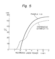
- Example 1-16 By use of the optical recording medium prepared in Example 1-16, C/N ratio was measured by varying the recording laser power from 0.5 mW to 7 mW in the evaluation of Example 1-16 for examination of the threshold value. The results are shown in Fig. 5.
- Example 1- For the optical recording medium of Example 1-31, a clear threshold value not recorded at a low power of laser power of 2 mW or less can be obtained. In contrast, in Comparative example 1-3, the threshold value was not clear as recorded at a lower power of 2 mW or lower. This indicates that deterioration will readily occur during repeated reproduction.
- Example 1-31 higher C/N value could be obtained as compared with Comparative example 1-3.
- optical recording media were prepared and evaluated similarly as in Examples 1-32 and 1-33. The results are shown in Table 1-12.
- PMMA polymethyl methacrylate
- a pre-group with a thickness of 50 ⁇ was provided by use of an epoxy-acrylate type UV-ray curable resin according to the 2P method (the photo-polymer method), and a liquid having the above polymethine type dye compound No. D-38 and the above aminium salt compound No. A-9 dissolved at a weight ratio of 80:20 in 1,2-dichloroethane was applied according to spinner coating, followed by drying, to obtain an organic thin film layer of 850 ⁇ .
- the thus prepared optical recording medium was mounted on a turn table, and under rotation of the turn table by a motor at 1800 rpm, information was written at a recording power of 6 mW and a recording frequency of 2MHz by use of a semiconductor laser of an oscillation wavelength of 830 nm on the organic thin film recording layer with a spot size of 1.5 ⁇ m0 ⁇ , reproduced with a reading power of 0.8 mW, and the reproduced waveform was spectrally analyzed (scanning filter, band width 30 KHz) to measure the C/N ratio (carrier/oise ratio).
- the same recording medium prepared under the same conditions was left to stand under the conditions of 45 °C, 95% RH for 3000 hours to perform environmental storage stability test, followed by measurement of reflectance (at 830 nm) and C/N ratio. Also, the same recording medium was irradiated with xenon lamp light of 1000 W/m2 (300 - 900 nm) for 100 hours for testing light stability resistance, and thereafter reflectance (at 8.30 nm) and C/N ratio were measured. The results are shown in Table 2-1.
- Example 2-1 By replacing the polymethine dye and the aminium salt compound (A) used in Example 2-1 with the combinations shown below in Table 2-2, recording media were prepared according to the same procedure as in Example 2-1 to give optical recording media of Examples 2-2 to 2-9, respectively.
- optical recording media of the above Examples 2-2 to 2-9 were measured according to the same method as in Example 2-1 to obtain the results shown in Table 2-4.
- a liquid comprising a mixture of 4 parts by weight of a combination of a polymethine dye (D) and an aminium compound (A) shown below in Table 2-3 and 1 part by weight of a nitrocellulose resin (OH-less Lacquer produced by Dicel K.K.) with 95 parts by weight of methyl ethyl ketone was applied by spinner coating onto a polycarbonate substrate of 130 mm o in diameter and 1.2 mm in thickness provided with a pre-group to obtain an organic thin film recording layer with a dried film thickness of 950 ⁇ .
- optical recording medium thus prepared was measured according to the same method as in Example 1-1 to give the results shown in Table 2-4.
- Optical recording media were prepared and evaluated according to the same method as in Example 2-1 except for omitting the aminium salt compounds No. A-9 and A-26 respectively used in Examples 2-1 and 2-6. The results are shown in Table 2-4.
- a pre-group was provided by the hot press method and a mixture of a cyclic polymethine compound and an aminium salt compound as indicated below in Table 2-5 in diacetoalcohol was applied by the bar coating method, followed by drying, to form an organic thin film recording layer of 850 ⁇ . Further, on the layer, through an ethylene-vinyl acetate film, a PC substrate of Waret size with a thickness of 0.3 mm was provided according to the hot roll method to prepare an optical recording medium with a closely adhered structure.
- PC polycarbonate of Waret size with a thickness of 0.4 mm
- optical recording media of Examples 2-14 to 2-17 thus prepared were each mounted on the stage driven in the X-Y direction, and information was written in the Y-axis direction with a spot size of 3.0 ⁇ mo at a recording power of 4.0 mW and a recording pulse of 80 u sec. by use of a semiconductor laser of oscillation wavelength of 830 nm from the PC substate side with a thickness of 0.4 mm on the organic thin recording layer, and reproduced with a reading power of 0.4 mW, to measure its contrast ratio [(A - B)/A: A is signal intensity at non-recorded portion and B is signal intensity at recorded portion].
- Example 2-1 the same recording media prepared under the above conditions were subjected to the environmental storage stability tests and light stability resistance tests under the same conditions as in Example 2-1, and thereafter reflectance and contrast ratio were measured. The results are shown in Table 2-6.
- the diimonium salt compound was used, and recording media were prepared according to the combinations shown in Table 2-7, following otherwise the same procedure as in Example 2-18 to 2-21, respectively.
- optical recording media of the above Examples 2-18 to 2-21 were measured according to the same method as in Example 2-1 to obtain the results shown in Table 2-9.
- the diimonium salt compound was used, and recording media were prepared according to the combinations shown in Table 2-8, following otherwise the same procedure as in Examples 2-10, to provide optical recording media of Examples 2-22 to 2-25, respectively.
- optical recording media of the above Examples 2-22 to 2-25 were measured according to the same method as in Example 2-1 to obtain the results shown in Table 2-9.
- aminium salt compound (A) used in Example 2-14 was replaced with the diimonium salt compound (I), and according to the combinations indicated in Table 2-10, recording media were prepared by the same method as in Example 2-14 to provide optical recording media of Examples 2-26 to 2-29.
- optical recording media of the above Examples 2-26 to 2-29 were measured according to the same method as in Example 2-14 to obtain the results shown in Table 2-11.
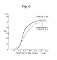
- Example 2-19 In evaluation of Example 2-19 by use of the optical recording medium prepared in Example 2-19, C/N ratio was measured by varying the recording laser power from 0.5 mW to 7 mW for examination of the threshold value. The results are shown in Fig. 6.
- Example 2- For the optical recording medium of Example 2-30, a clear threshold value not recorded at a low power of laser power of 2 mW or less can be obtained. In contrast, in Comparative example 2-3, the threshold value was not clear as recorded at a lower power of 2 mW or lower. This indicates that deterioration will readily occur during repeated reproduction.
- Example 2-30 higher C/N value could be obtained as compared with Comparative example 2-3.
- optical recording media were prepared in the same manner as in Example 2-31 and evaluated. The results are shown in Table 2-12.
Landscapes
- Thermal Transfer Or Thermal Recording In General (AREA)
- Optical Record Carriers And Manufacture Thereof (AREA)
Applications Claiming Priority (4)
| Application Number | Priority Date | Filing Date | Title |
|---|---|---|---|
| JP24460986 | 1986-10-14 | ||
| JP244609/86 | 1986-10-14 | ||
| JP25330186 | 1986-10-23 | ||
| JP253301/86 | 1986-10-23 |
Publications (2)
| Publication Number | Publication Date |
|---|---|
| EP0264274A2 true EP0264274A2 (de) | 1988-04-20 |
| EP0264274A3 EP0264274A3 (en) | 1989-02-01 |
Family
ID=26536810
Family Applications (1)
| Application Number | Title | Priority Date | Filing Date |
|---|---|---|---|
| EP87309095A Withdrawn EP0264274A3 (en) | 1986-10-14 | 1987-10-14 | Optical recording medium |
Country Status (1)
| Country | Link |
|---|---|
| EP (1) | EP0264274A3 (de) |
Cited By (4)
| Publication number | Priority date | Publication date | Assignee | Title |
|---|---|---|---|---|
| EP0353007A3 (en) * | 1988-07-27 | 1990-05-23 | Minnesota Mining And Manufacturing Company | Polymethine dyes suitable for optical recording media |
| EP0352068A3 (en) * | 1988-07-18 | 1990-06-27 | Hitachi Maxell Ltd. | Optical data recording medium |
| EP0347183A3 (de) * | 1988-06-14 | 1991-09-25 | Fuji Photo Film Co., Ltd. | Farbstofflösung und Verfahren zur Herstellung eines Informationsaufzeichnungsmedium |
| EP0554627A1 (de) * | 1992-01-06 | 1993-08-11 | Canon Kabushiki Kaisha | Aminium-Salzverbindung und optisches Aufzeichnungsmedium |
Family Cites Families (3)
| Publication number | Priority date | Publication date | Assignee | Title |
|---|---|---|---|---|
| DE3503995A1 (de) * | 1984-02-06 | 1985-08-08 | Ricoh Co., Ltd., Tokio/Tokyo | Optischer informationsaufzeichnungstraeger |
| DE3537539A1 (de) * | 1984-10-23 | 1986-04-24 | Ricoh Co., Ltd., Tokio/Tokyo | Optisches informationsaufzeichnungsmaterial |
| GB8712646D0 (en) * | 1987-05-29 | 1987-07-01 | Clayton Found Res | Structural evidence |
-
1987
- 1987-10-14 EP EP87309095A patent/EP0264274A3/en not_active Withdrawn
Cited By (6)
| Publication number | Priority date | Publication date | Assignee | Title |
|---|---|---|---|---|
| EP0347183A3 (de) * | 1988-06-14 | 1991-09-25 | Fuji Photo Film Co., Ltd. | Farbstofflösung und Verfahren zur Herstellung eines Informationsaufzeichnungsmedium |
| EP0352068A3 (en) * | 1988-07-18 | 1990-06-27 | Hitachi Maxell Ltd. | Optical data recording medium |
| US4996089A (en) * | 1988-07-18 | 1991-02-26 | Hitachi Maxell, Ltd. | Optical data recording medium |
| EP0353007A3 (en) * | 1988-07-27 | 1990-05-23 | Minnesota Mining And Manufacturing Company | Polymethine dyes suitable for optical recording media |
| EP0554627A1 (de) * | 1992-01-06 | 1993-08-11 | Canon Kabushiki Kaisha | Aminium-Salzverbindung und optisches Aufzeichnungsmedium |
| US5605732A (en) * | 1992-01-06 | 1997-02-25 | Canon Kabushiki Kaisha | Aminium salt compound and optical recording medium |
Also Published As
| Publication number | Publication date |
|---|---|
| EP0264274A3 (en) | 1989-02-01 |
Similar Documents
| Publication | Publication Date | Title |
|---|---|---|
| US4735839A (en) | Optical information recording medium | |
| US5190849A (en) | Optical recording medium containing carboxylic acid-base metallic complex and squarylium-base or croconium-base dye | |
| EP0295144B1 (de) | Optischer Aufzeichnungsträger | |
| EP0554627A1 (de) | Aminium-Salzverbindung und optisches Aufzeichnungsmedium | |
| EP0264274A2 (de) | Medium für optische Aufzeichnung | |
| EP0838463B1 (de) | Squaryliumverbindungen und diese benutzende optische Informationsaufzeichnungsmittel | |
| EP0264198B1 (de) | Medium für optische Informationsaufzeichnung | |
| JP2874888B2 (ja) | 珪素ナフタロシアニン及びこの化合物を含有する感光性塗装薄膜 | |
| JP3412078B2 (ja) | 光記録媒体 | |
| JP2605116B2 (ja) | 光情報記録媒体 | |
| US4965178A (en) | Optical recording medium | |
| JPH0624146A (ja) | 赤外吸収化合物及びそれを用いた光記録媒体 | |
| US5271979A (en) | Optical recording medium containing polymethine compound | |
| JPS63226642A (ja) | 光学記録媒体 | |
| JP2649672B2 (ja) | 光学的記録媒体 | |
| JP2530443B2 (ja) | 光学的記録媒体 | |
| JP3039739B2 (ja) | アミニウム塩化合物及びそれを用いた光記録媒体 | |
| JPH0316785A (ja) | 光記録媒体 | |
| JP2510529B2 (ja) | 光学情報記録媒体 | |
| JP2602078B2 (ja) | アミニウム塩化合物、ジイモニウム塩化合物及び光記録媒体 | |
| JPH07133475A (ja) | 赤外吸収化合物及びそれを用いた光記録媒体 | |
| JP3005111B2 (ja) | 光記録媒体、情報記録方法及び光記録媒体の製造方法 | |
| US5187043A (en) | Optical recording medium | |
| JP2740851B2 (ja) | 光情報記録媒体 | |
| JPH03254991A (ja) | 光情報記録媒体 |
Legal Events
| Date | Code | Title | Description |
|---|---|---|---|
| PUAI | Public reference made under article 153(3) epc to a published international application that has entered the european phase |
Free format text: ORIGINAL CODE: 0009012 |
|
| AK | Designated contracting states |
Kind code of ref document: A2 Designated state(s): DE FR GB |
|
| PUAL | Search report despatched |
Free format text: ORIGINAL CODE: 0009013 |
|
| AK | Designated contracting states |
Kind code of ref document: A3 Designated state(s): DE FR GB |
|
| 17P | Request for examination filed |
Effective date: 19890705 |
|
| 17Q | First examination report despatched |
Effective date: 19900508 |
|
| STAA | Information on the status of an ep patent application or granted ep patent |
Free format text: STATUS: THE APPLICATION IS DEEMED TO BE WITHDRAWN |
|
| 18D | Application deemed to be withdrawn |
Effective date: 19901120 |
|
| RIN1 | Information on inventor provided before grant (corrected) |
Inventor name: OGUCHI, YOSHIHIRO Inventor name: FUKUI, TETSURO Inventor name: SUGATA, HIROYUKI Inventor name: MIURA, KYO Inventor name: TAKASU, YOSHIO |