EP0264314A1 - Mehrpoliger Differentialmodulschutzschalter - Google Patents
Mehrpoliger Differentialmodulschutzschalter Download PDFInfo
- Publication number
- EP0264314A1 EP0264314A1 EP87402073A EP87402073A EP0264314A1 EP 0264314 A1 EP0264314 A1 EP 0264314A1 EP 87402073 A EP87402073 A EP 87402073A EP 87402073 A EP87402073 A EP 87402073A EP 0264314 A1 EP0264314 A1 EP 0264314A1
- Authority
- EP
- European Patent Office
- Prior art keywords
- differential
- circuit
- circuit breaker
- test
- block
- Prior art date
- Legal status (The legal status is an assumption and is not a legal conclusion. Google has not performed a legal analysis and makes no representation as to the accuracy of the status listed.)
- Granted
Links
- 230000005405 multipole Effects 0.000 title claims description 5
- 238000012360 testing method Methods 0.000 claims abstract description 51
- 230000007246 mechanism Effects 0.000 claims abstract description 23
- 230000035945 sensitivity Effects 0.000 claims description 15
- 238000004804 winding Methods 0.000 claims description 14
- 238000012545 processing Methods 0.000 claims description 6
- 238000011144 upstream manufacturing Methods 0.000 claims description 5
- 238000005259 measurement Methods 0.000 claims description 4
- 238000001514 detection method Methods 0.000 claims description 3
- 239000004020 conductor Substances 0.000 description 21
- 230000001681 protective effect Effects 0.000 description 10
- 210000002105 tongue Anatomy 0.000 description 5
- 230000005540 biological transmission Effects 0.000 description 4
- 238000010586 diagram Methods 0.000 description 4
- 230000007935 neutral effect Effects 0.000 description 4
- 239000003990 capacitor Substances 0.000 description 2
- 230000001960 triggered effect Effects 0.000 description 2
- 230000015556 catabolic process Effects 0.000 description 1
- 230000009849 deactivation Effects 0.000 description 1
- 238000006731 degradation reaction Methods 0.000 description 1
- 230000003111 delayed effect Effects 0.000 description 1
- 230000000881 depressing effect Effects 0.000 description 1
- 230000000994 depressogenic effect Effects 0.000 description 1
- 238000011161 development Methods 0.000 description 1
- 230000000694 effects Effects 0.000 description 1
- 230000005284 excitation Effects 0.000 description 1
- 238000003780 insertion Methods 0.000 description 1
- 230000037431 insertion Effects 0.000 description 1
- 239000011810 insulating material Substances 0.000 description 1
- 239000007769 metal material Substances 0.000 description 1
- 238000012986 modification Methods 0.000 description 1
- 230000004048 modification Effects 0.000 description 1
- 230000002035 prolonged effect Effects 0.000 description 1
- 230000004044 response Effects 0.000 description 1
- 238000003466 welding Methods 0.000 description 1
Images




Classifications
-
- H—ELECTRICITY
- H01—ELECTRIC ELEMENTS
- H01H—ELECTRIC SWITCHES; RELAYS; SELECTORS; EMERGENCY PROTECTIVE DEVICES
- H01H83/00—Protective switches, e.g. circuit-breaking switches, or protective relays operated by abnormal electrical conditions otherwise than solely by excess current
- H01H83/02—Protective switches, e.g. circuit-breaking switches, or protective relays operated by abnormal electrical conditions otherwise than solely by excess current operated by earth fault currents
- H01H83/04—Protective switches, e.g. circuit-breaking switches, or protective relays operated by abnormal electrical conditions otherwise than solely by excess current operated by earth fault currents with testing means for indicating the ability of the switch or relay to function properly
-
- H—ELECTRICITY
- H02—GENERATION; CONVERSION OR DISTRIBUTION OF ELECTRIC POWER
- H02H—EMERGENCY PROTECTIVE CIRCUIT ARRANGEMENTS
- H02H3/00—Emergency protective circuit arrangements for automatic disconnection directly responsive to an undesired change from normal electric working condition with or without subsequent reconnection ; integrated protection
- H02H3/02—Details
- H02H3/05—Details with means for increasing reliability, e.g. redundancy arrangements
-
- H—ELECTRICITY
- H01—ELECTRIC ELEMENTS
- H01H—ELECTRIC SWITCHES; RELAYS; SELECTORS; EMERGENCY PROTECTIVE DEVICES
- H01H83/00—Protective switches, e.g. circuit-breaking switches, or protective relays operated by abnormal electrical conditions otherwise than solely by excess current
- H01H83/02—Protective switches, e.g. circuit-breaking switches, or protective relays operated by abnormal electrical conditions otherwise than solely by excess current operated by earth fault currents
- H01H83/04—Protective switches, e.g. circuit-breaking switches, or protective relays operated by abnormal electrical conditions otherwise than solely by excess current operated by earth fault currents with testing means for indicating the ability of the switch or relay to function properly
- H01H2083/045—Auxiliary switch opening testing circuit in synchronism with the main circuit
-
- H—ELECTRICITY
- H01—ELECTRIC ELEMENTS
- H01H—ELECTRIC SWITCHES; RELAYS; SELECTORS; EMERGENCY PROTECTIVE DEVICES
- H01H71/00—Details of the protective switches or relays covered by groups H01H73/00 - H01H83/00
- H01H71/10—Operating or release mechanisms
- H01H71/1009—Interconnected mechanisms
- H01H71/1018—Interconnected mechanisms with only external interconnections
Definitions
- the invention relates to a differential protection multipole electric circuit breaker comprising a modular assembly of a circuit breaker block having a multipole breaking device with separable contacts actuated by a joystick control mechanism, and a differential trip block comprising a trip relay , a first mechanical link capable of transmitting a triggering order from the relay to the control mechanism, when a differential current appears, a second mechanical link to derive from the opening movement of the lever an automatic reset movement of the relay, and a test circuit having at least one test resistor in a leakage derivative circuit, a test button the closing of which creates an artificial differential current, and a protection switch intended to disconnect the test resistance and to interrupt the artificial differential current in the test circuit after opening of the circuit breaker by dec differential triggering.
- the differential trip unit of a miniature circuit breaker generally contains the differential current detector formed by a transformer in the form of a toroid surrounding the active conductors of the network to be protected.
- the secondary winding is directly connected to the trip relay, and it is therefore essential to have a trip unit for each trip sensitivity.
- an electronic circuit is interposed between the secondary winding and the relay to obtain a highly sensitive differential protection device. A special trigger block is also required. The number of different trip units poses storage and cost problems for a range of miniature circuit breakers.
- the object of the invention is to provide a circuit breaker modular differential using the maximum of common parts for each of the electromechanical or electronic versions.
- the circuit breaker according to the invention is characterized in that one of the faces of the housing of the trip unit coming into engagement with the circuit breaker unit has openings for transverse passage of the first and second mechanical connections, and that the other opposite face of the housing alternately serves as a support, either for a detector block containing a totalizing transformer for the detection of a residual differential current, or for an auxiliary block containing an electronic circuit controlled by trip and supply signals from the separate detector block.
- the differential trip unit is connected by an internal electrical connection, either to the measuring winding of the transformer incorporated in the detector unit, or to the electronic circuit board of the auxiliary unit. It is noted that the structures of the circuit breaker block, the trip block and the detector block are identical for each version, the only modification being the presence or absence of the auxiliary block with appropriate wiring.
- the front panel of the auxiliary unit is fitted with a differential trigger sensitivity adjustment selector, and a time-out button for adjusting the differential trigger delay.
- the trigger block includes an integrated remote opening command by artificial differential trigger, and a differential trigger viewing window, located near the test button.
- the detector block is electronically connected by a ribbon cable to a connector of the electronic circuit of the auxiliary block so as to transmit the power supply and the differential current measurement signal to the electronic circuit board, and to ensure the connection of the test circuit with the network upstream and downstream of the transformer.
- the electronic circuit includes load resistors for the secondary winding of the transformer, cooperating with the adjustment selector to choose the differential tripping sensitivity, said selector being in connection with an auxiliary switch intended to be actuated by the test button to force the automatic switching of the selector to the highest sensitivity when the test circuit is closed.
- FIG. 1 shows the electrical diagram of a bipolar differential circuit breaker inserted in a single-phase alternating network having a phase conductor L and a neutral conductor N.
- the differential circuit breaker 10 comprises a breaking device 12 bipolar or unipolar and neutral with separable contacts 14, 16 actuated by a joystick control mechanism 18, which cooperates with a thermomagnetic trip device (not shown) sensitive to overload and short-circuit currents, and a differential trip device 20 sensitive to a ground leakage current .
- the differential trip device 20 comprises a residual differential current detector formed by a totalizing transformer 21 for detecting a zero sequence current, having a toric core 22 surrounding the active conductors L and N, and a measurement winding 24 wound on the core 22.
- the measuring winding 24 is electrically connected to a polarized electromagnetic relay 26 for triggering cooperating with the mechanism 18 via a first mechanical triggering link 27 so as to cause the automatic opening of the contacts 14, 16, when the appearance of a differential fault in conductors L and N.
- a test circuit 28 is associated with the differential trip device 20 by being electrically connected by a conductor 29 to a first connection point 30 of the phase conductor L, and by a conductor 31 at a second connection point 32 of the neutral conductor N, respectively upstream and downstream of the totalizing transformer 21.
- the circuit test 28 constitutes a leakage derivative circuit comprising a pair of resistors 34, 36 for testing, an interruption or protection device 38 with double contacts 40, 42, and a push button test button 44. Manual closing of the test button 44 simulates a differential current by inserting resistors 34, 36 in the test circuit 28, making it possible to verify the proper functioning of the differential trigger.
- the artificial differential current flows in the test circuit 28 from the first point of connection 30 of phase conductor L through resistance 36, protective contact 40, test button 44, protective contact 42, resistance 34, to return to the second connection point of neutral conductor N.
- the opening of the protective contacts 40, 42 of the interruption device 38 intervenes automatically thanks to a second mechanical connection 45 of the mechanism 18, causing the two circuits to be switched off. resistors 34, 36, even in the event of prolonged pressing of the test button 44.
- the interruption device 38 of the test circuit 28 is located between the test button 44 and the resistors 34, 36.
- a remote trip control can be associated with the mechanism 18 of the circuit breaker 10, and includes a single remote control contact 46 inserted in a link circuit 48 capable of being electrically connected in parallel to the terminals 50, 52 of the test button 44.
- L actuation of the remote control contact 46 provides the same effect as the local closing of the test button 44, that is to say an opening of the contacts 14, 16 of the circuit breaker 10 by differential tripping.
- the presence in the test circuit 28 of the two protective contacts 40, 42 of the interruption device 38 allows after differential tripping to completely isolate the test button 44 and the remote control contact 46 from the network.
- the power off by complete disconnection of the two buttons 44, 46 is effected by the simultaneous interruption of the two conductors 29, 31, independently of the mode of connection of the circuit breaker 10, that is to say in the event of supply by upstream (terminals 51, 53) or opposite supply from downstream (terminals 54, 56).
- test resistor 34, 36 in each conductor 31, 29 of the test circuit 28 makes it possible to obtain total safety for the user, even in the event of accidental welding of one of the protective contacts 40, 42 .
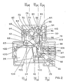
- the mechanism 60 of the differential trip unit 20 is housed in an insulating box 62 capable of being juxtaposed and coupled to the circuit breaker unit 11 containing the breaking device 12, the mechanism 18 and the magnetothermal trip device.
- the trigger relay 26 of the mechanism 60 comprises a movable pallet (not shown) capable of cooperating with an arm 63 for actuating a drive lever 64 pivotally mounted on an axis 66 between an armed position and a triggered position.
- the drive lever 64 carries a finger 68 constituting the first mechanical triggering link 27 intended to release the latch of the mechanism 18 of the circuit breaker 10 when the pallet of the relay 26 is actuated towards the tripped position following a differential fault.
- the second mechanical link 45 of the differential mechanism 60 connects the lever 19 of the mechanism 18 of the circuit breaker 10 to a transmission cam 70 pivotally mounted on an axis 72 so as to follow the opening and closing movements of the lever 19.
- the transmission cam 70 cooperates on the one hand with an arm 74 of a reset lever 76 and on the other hand with an indicator lever 78, both pivotally mounted on the same axis 80.
- a lock 82 (fig. 2 and 4) is pivotally mounted on an axis 84 and has a retaining spout 86 capable of locking the indicator lever 78 in an inactive position in which an indicator 88 is moved away from a viewing window 90 formed in the front face of the housing 62.
- a spring 92 of the torsion type made of electrically conductive metallic material.
- One of the ends 94 of the spring 92 is supported on a flange of the reset lever 76 so as to urge it clockwise, in support of the cam 70.
- the end 94 of the spring can cooperate on the other hand with a first fixed conductive tongue 96 to constitute the protective contact 40 of the interruption device 38 of the test circuit 28.
- the other end 97 of the spring 92 is in engagement against a stop 98 of the housing 62, and is connected to the resistor 36 electrically connected by the conductor 29 at the first connection point 30 of the phase conductor L.
- the other protective contact 42 of the interruption device 38 comprises a second fixed conductive tab 100 capable of cooperating with an elastic contact piece 102.
- the opposite end of this blade 102 is secured to a fixed anchor 104 of the housing 62 surrounding the pivot axis 66 of the drive lever 64, and is electrically connected to the resistor 34 inserted in the conductor 31 of the test circuit 28.
- the contact blade 102 is actuated by a finger 103 of the reset lever 76.
- the two fixed tabs 96, 100 are respectively connected to two plugs 106, 108 for connecting the connection circuit 48 of the remote control contact 46, the two plugs 106, 108 being in electrical connection with the terminals 50, 52 of the test button 44.
- a plug 110 can block the access opening to the plugs 106, 108 when the remote trip control is not connected to the differential trip device 20.
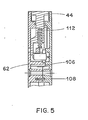
- the test button 44 is equipped with a deformable elastic blade 112 described in detail in French Patent No. 2 526 995.
- the blade 112 comes into contact in the depressed position of the test button 44, with the first fixed tongue 96 of the protective contact 40.
- the second mechanical link 45 with the mechanism 18 derives from the opening movement of the circuit breaker, an automatic resetting movement of the relay 26 by means of the drive lever 64 urged by the reset lever 76.
- the indicator lever 78 brings about on the other hand, the indicator in an active position opposite the viewing window 90 to signal the trip on differential fault.
- the second mechanical link 45 returns the reset lever 76 and the indicator lever 78 to their original position during manual movement of the lever 19 from the open position to the closed position of the circuit breaker.
- a differential fault is simulated by depressing the push button 44 causing the resistors 34, 36 to be inserted into the test circuit 28.
- the elastic contact blade 112 comes into contact with the terminal 50 of the first tongue 96.
- the two protective contacts 40, 42 open automatically by the pivoting movement of the reset lever 76 clockwise.
- the end 94 of the spring 92 and the contact blade 102 deviate respectively from the first and second tongues 96, 100 fixed, and ensure the deactivation of the two resistors 34, 36.
- the test circuit 28 is thus temporarily kept energized during the response time of mechanism 18 of the circuit breaker. Terminals 50, 52 and plugs 106, 108 are de-energized when the circuit breaker is open.
- the reset lever 76 urges the protective contacts 40, 42 in the closed position. A new test can then be performed.
- the arm 63 for actuating the lever 64 is common to the first and second mechanical connections 27, 45, and serves both as a triggering member, when a triggering signal is sent to the coil of the relay 26, and of relay 26 reset member, when the circuit breaker opens.
- the arm 63 is associated with an elastic tongue 120 (FIG. 2) made of insulating material, intended to maintain a predetermined clearance 122 between the arm 63 and the pallet after resetting of the relay 26, and when the handle 19 of the circuit breaker 10 is moved from the open position to the closed position. The presence of this clearance allows good transmission of the trip order from relay 26.
- FIGS. 6 and 7 show the modular assembly of the differential circuit breaker 10 according to FIG. 1, with the electromechanical differential trip unit 20 interposed between the bipolar circuit breaker unit 11 and the detector block 150 with totalizing transformer 21 for the detection of residual differential current.
- the secondary winding 24 of the transformer 21 incorporated in the detector unit 150 is connected to the coil of the relay 26 of the differential trip unit 20 by an internal electrical link 152.
- Each pole of the unit breaker 11 is for example you type described in French patent application No. 86 00111 filed on 01.03.86 by the applicant, but any other multi miniature circuit breaker can be used.
- the lever 19 is mechanically coupled to the second mechanical link 45 of the differential trigger block 20, while the first mechanical trigger link 27 controls the latch of the mechanism 18.
- the differential circuit breaker 10 comprises a pair of intermediate connecting conductors 154, 156 connected between the lower terminals 158, 160 of the bipolar circuit breaker block 11 and the upper terminals 162, 164 of the detector block 150.
- the differential circuit breaker 10 is supplied with power with its own current, and the connection of the conductors L, N of the network takes place at the upstream terminals 51, 53 of the circuit breaker block 11, and at the downstream terminals 54, 56 of the detector block 150.
- the toroid 22 of the totalizing transformer 21 has two coils primary 166, 168, the opposite ends of which are connected to the upper 162, 164 and downstream 54, 56 corresponding terminals of the detector block 150.
- the entry of the intermediate conductors 154, 156 into the detector block 150 takes place through openings 170, 172 arranged under the downstream terminals 54, 56.
- FIGS. 8 to 10 relate to an alternative embodiment of an electronic differential circuit breaker 200 with an auxiliary power source.
- the same reference numbers will be used to designate parts identical or similar to those of the circuit breaker 10 in FIGS. 1 to 7.
- the differential circuit breaker 200 comprises a modular assembly of a bipolar circuit breaker block 11 attached to the differential trip block 20, and to a auxiliary unit 202 containing an electronic circuit 204 for processing signals from the separate detector unit 150.
- a ply 206 of five connecting wires connects the detector block 150 to an input connector 208 of the electronic circuit 204 to ensure on the one hand the emission of a first measurement signal of the secondary winding 24, and a second signal for the power source Vcc, and on the other hand the connection of the test circuit 28 of the differential trip unit 20 with push button 44.
- the electronic circuit 204 of the auxiliary block 202 is connected to the relay 26, to the test circuit 28 and to the test buttons 44 and of the remote control 46 of the trip unit 20 by an internal connection 210 of eight wires.
- the front face of the auxiliary electronic unit 202 is provided with an adjustment selector 212 of the differential tripping sensitivity (for example 30 m A, 300 m A, 1 A, 3 A), and a timer button 214 for the differential trigger delay setting.
- an adjustment selector 212 of the differential tripping sensitivity for example 30 m A, 300 m A, 1 A, 3 A
- a timer button 214 for the differential trigger delay setting.
- the electronic circuit 204 (fig. 9) of the auxiliary unit 202 includes a network of resistors R0, R1, R2, R3, for adjusting the sensitivity, and the secondary winding 24 of the transformer 21 totalizer is charged by one or more of these resistors R0 to R3 depending on the position of the selector 212.
- the highest sensitivity of 30 m A corresponds to the insertion of the resistance R0, while the sensitivities of 300 m A, 1 A, and 3 A correspond when paralleling R1, R2, R3 with resistance R0.
- the output of the resistance network R0 to R3 is connected to an operational amplifier 216, arranged as a comparator which controls a processing circuit 218 of the differential trigger signal.
- the remote control contact 46 is connected directly to the processing circuit 218 by resistors 220, 222.
- the output of the processing circuit 218 is connected to one of the inputs of an OR logic gate 224 which controls the excitation of the coil of trigger relay 26.
- the output terminal 226 of the secondary winding 24 of the transformer 21 is connected by a resistor 228 to the power source Vcc, and by a capacitor 230 to the network of resistors R0 to R3.
- the other input of the OR logic gate 224 is connected by a conductor 232 to the terminal 226 of the winding 24. Poor continuity of the secondary circuit of the detector block 150 causes a potential rise in the terminal 226, delayed by the constant time RC of the resistor 228 and of the capacitor 230.
- the OR logic gate 224 can thus receive two trip orders comprising a first trip signal on differential fault produced by the processing circuit 218, and a second trip signal on fault of continuity of the secondary circuit. The two trip signals are discriminated by the opening times of the RCD 200.
- the sensitivity adjustment selector 212 is connected to ground via an auxiliary switch 232 (figs. 8 and 9).
- the latter is housed in the trip unit 20 and is actuated when the test button 44 is pressed (see fig. 2 and 5), causing with the closing of the test circuit 28 an automatic interruption of the connection of the selector 212 with the ground .
- the selector 212 or of the auxiliary switch 232 leads to an increase in the sensitivity of the electronic circuit 204.
- the detector block 150 is part of the modular assembly, being necessarily attached to the trip block 20.
- the auxiliary block 202 of the electronic circuit 204 is placed side by side with the trip unit 20, while the detector unit 150 is physically separated from the modular assembly, with simple electrical connections to the circuit breaker unit 11 (conductors 154, 156), and the electronic circuit 204 (tablecloth 206).
Landscapes
- Breakers (AREA)
- Protection Of Generators And Motors (AREA)
- Multiple-Way Valves (AREA)
- Emergency Protection Circuit Devices (AREA)
- Coupling Device And Connection With Printed Circuit (AREA)
- Keying Circuit Devices (AREA)
- Stand-By Power Supply Arrangements (AREA)
Priority Applications (1)
| Application Number | Priority Date | Filing Date | Title |
|---|---|---|---|
| AT87402073T ATE84915T1 (de) | 1986-09-23 | 1987-09-16 | Mehrpoliger differentialmodulschutzschalter. |
Applications Claiming Priority (2)
| Application Number | Priority Date | Filing Date | Title |
|---|---|---|---|
| FR8613369A FR2604294B1 (fr) | 1986-09-23 | 1986-09-23 | Disjoncteur differentiel multipolaire a assemblage modulaire |
| FR8613369 | 1986-09-23 |
Publications (2)
| Publication Number | Publication Date |
|---|---|
| EP0264314A1 true EP0264314A1 (de) | 1988-04-20 |
| EP0264314B1 EP0264314B1 (de) | 1993-01-20 |
Family
ID=9339246
Family Applications (1)
| Application Number | Title | Priority Date | Filing Date |
|---|---|---|---|
| EP87402073A Expired - Lifetime EP0264314B1 (de) | 1986-09-23 | 1987-09-16 | Mehrpoliger Differentialmodulschutzschalter |
Country Status (12)
| Country | Link |
|---|---|
| EP (1) | EP0264314B1 (de) |
| JP (1) | JPS6388729A (de) |
| CN (1) | CN1021388C (de) |
| AT (1) | ATE84915T1 (de) |
| AU (1) | AU601490B2 (de) |
| DE (1) | DE3783704T2 (de) |
| ES (1) | ES2040270T3 (de) |
| FR (1) | FR2604294B1 (de) |
| IN (1) | IN170069B (de) |
| PT (1) | PT85770B (de) |
| TN (1) | TNSN87104A1 (de) |
| YU (1) | YU173687A (de) |
Cited By (14)
| Publication number | Priority date | Publication date | Assignee | Title |
|---|---|---|---|---|
| GB2247568A (en) * | 1990-08-30 | 1992-03-04 | Mk Electric Ltd | Circuitbreaker electrical control apparatus |
| EP0437220A3 (en) * | 1990-01-12 | 1992-07-01 | Mitsubishi Denki Kabushiki Kaisha | Circuit breaker with leakage current detecting functions |
| EP0502393A3 (en) * | 1991-03-02 | 1992-12-09 | Abb Patent Gmbh | Ground fault circuit interrupter |
| EP0357472B1 (de) * | 1988-08-30 | 1993-12-15 | Hager Electro S.A. | Elektrische Schalt- und/oder Schutzgeräte, Bestandteile dieser Geräte und aus diesen Teilen gebildete Baugruppen |
| EP0641045A1 (de) * | 1993-08-31 | 1995-03-01 | CMC Carl Maier + Cie AG | Fehlerstromgeschützte Steckdose |
| DE29504864U1 (de) * | 1995-03-22 | 1995-05-18 | Siemens AG, 80333 München | Fehlerstromschutzschalter in Modulbauweise |
| EP0924837A3 (de) * | 1997-12-22 | 2000-11-02 | Siemens Aktiengesellschaft | Zusatzeinrichtung für Schutzeinrichtungen, insbesondere für Fehlerstrom- bzw. Differenzstromschutzeinrichtungen |
| US6919785B2 (en) | 2000-05-16 | 2005-07-19 | General Electric Company | Pressure sensitive trip mechanism for a rotary breaker |
| EP1432002A3 (de) * | 2002-12-16 | 2005-09-14 | Stefan Goethe | Schutzvorrichtung |
| US6995640B2 (en) | 2000-05-16 | 2006-02-07 | General Electric Company | Pressure sensitive trip mechanism for circuit breakers |
| CN106504954A (zh) * | 2016-12-15 | 2017-03-15 | 苏州未来电器股份有限公司 | 具有漏电保护功能及分合闸功能的断路器 |
| CN106504957A (zh) * | 2016-12-15 | 2017-03-15 | 苏州未来电器股份有限公司 | 具有漏电保护功能的断路器 |
| CN106710990A (zh) * | 2016-12-27 | 2017-05-24 | 温州圣普电气有限公司 | 小型断路器重合闸机构 |
| WO2019122539A1 (fr) * | 2017-12-22 | 2019-06-27 | Hager-Electro Sas | Appareil électrique de commutation de type modulaire |
Families Citing this family (77)
| Publication number | Priority date | Publication date | Assignee | Title |
|---|---|---|---|---|
| AT384907B (de) * | 1985-12-02 | 1988-01-25 | Felten & Guilleaume Ag Oester | Fehlerstrom- und leitungsschutzschalter |
| GB8913633D0 (en) * | 1989-06-14 | 1989-08-02 | Electrolux Northern | Electromagnetic actuator arrangement |
| DE4011336A1 (de) * | 1990-04-07 | 1991-10-10 | Felten & Guilleaume Energie | Fehlerstromschutzschalter in modulbauweise |
| DE4337254B4 (de) * | 1993-11-02 | 2005-05-19 | Aeg Niederspannungstechnik Gmbh & Co Kg | Fehlerstrommodul, der mit Leitungsschutzschaltern zusammensetzbar ist |
| IT1292453B1 (it) | 1997-07-02 | 1999-02-08 | Aeg Niederspannungstech Gmbh | Gruppo rotante di contatti per interrutttori di alta portata |
| FR2774822B1 (fr) † | 1998-02-11 | 2000-03-17 | Schneider Electric Ind Sa | Dispositif de protection differentielle |
| DE19819242B4 (de) | 1998-04-29 | 2005-11-10 | Ge Power Controls Polska Sp.Z.O.O. | Thermomagnetischer Leistungsschalter |
| US6114641A (en) | 1998-05-29 | 2000-09-05 | General Electric Company | Rotary contact assembly for high ampere-rated circuit breakers |
| US6087913A (en) | 1998-11-20 | 2000-07-11 | General Electric Company | Circuit breaker mechanism for a rotary contact system |
| US6037555A (en) | 1999-01-05 | 2000-03-14 | General Electric Company | Rotary contact circuit breaker venting arrangement including current transformer |
| US6166344A (en) | 1999-03-23 | 2000-12-26 | General Electric Company | Circuit breaker handle block |
| US6262872B1 (en) | 1999-06-03 | 2001-07-17 | General Electric Company | Electronic trip unit with user-adjustable sensitivity to current spikes |
| US6268991B1 (en) | 1999-06-25 | 2001-07-31 | General Electric Company | Method and arrangement for customizing electronic circuit interrupters |
| US6218917B1 (en) | 1999-07-02 | 2001-04-17 | General Electric Company | Method and arrangement for calibration of circuit breaker thermal trip unit |
| US6188036B1 (en) | 1999-08-03 | 2001-02-13 | General Electric Company | Bottom vented circuit breaker capable of top down assembly onto equipment |
| US6710988B1 (en) | 1999-08-17 | 2004-03-23 | General Electric Company | Small-sized industrial rated electric motor starter switch unit |
| US6252365B1 (en) | 1999-08-17 | 2001-06-26 | General Electric Company | Breaker/starter with auto-configurable trip unit |
| US6175288B1 (en) | 1999-08-27 | 2001-01-16 | General Electric Company | Supplemental trip unit for rotary circuit interrupters |
| US6396369B1 (en) | 1999-08-27 | 2002-05-28 | General Electric Company | Rotary contact assembly for high ampere-rated circuit breakers |
| US6232570B1 (en) | 1999-09-16 | 2001-05-15 | General Electric Company | Arcing contact arrangement |
| US6326869B1 (en) | 1999-09-23 | 2001-12-04 | General Electric Company | Clapper armature system for a circuit breaker |
| US6239395B1 (en) | 1999-10-14 | 2001-05-29 | General Electric Company | Auxiliary position switch assembly for a circuit breaker |
| US6229413B1 (en) | 1999-10-19 | 2001-05-08 | General Electric Company | Support of stationary conductors for a circuit breaker |
| US6317018B1 (en) | 1999-10-26 | 2001-11-13 | General Electric Company | Circuit breaker mechanism |
| US6232856B1 (en) | 1999-11-02 | 2001-05-15 | General Electric Company | Magnetic shunt assembly |
| ES2249875T3 (es) | 1999-11-03 | 2006-04-01 | AEG NIEDERSPANNUNGSTECHNIK GMBH & CO. KG | Disposicion de brazo de contacto rotatorio para disyuntor. |
| US6377144B1 (en) | 1999-11-03 | 2002-04-23 | General Electric Company | Molded case circuit breaker base and mid-cover assembly |
| US6300586B1 (en) | 1999-12-09 | 2001-10-09 | General Electric Company | Arc runner retaining feature |
| US6310307B1 (en) | 1999-12-17 | 2001-10-30 | General Electric Company | Circuit breaker rotary contact arm arrangement |
| US6184761B1 (en) | 1999-12-20 | 2001-02-06 | General Electric Company | Circuit breaker rotary contact arrangement |
| US6172584B1 (en) | 1999-12-20 | 2001-01-09 | General Electric Company | Circuit breaker accessory reset system |
| US6215379B1 (en) | 1999-12-23 | 2001-04-10 | General Electric Company | Shunt for indirectly heated bimetallic strip |
| US6281461B1 (en) | 1999-12-27 | 2001-08-28 | General Electric Company | Circuit breaker rotor assembly having arc prevention structure |
| US6346869B1 (en) | 1999-12-28 | 2002-02-12 | General Electric Company | Rating plug for circuit breakers |
| US6211758B1 (en) | 2000-01-11 | 2001-04-03 | General Electric Company | Circuit breaker accessory gap control mechanism |
| US6239677B1 (en) | 2000-02-10 | 2001-05-29 | General Electric Company | Circuit breaker thermal magnetic trip unit |
| US6429759B1 (en) | 2000-02-14 | 2002-08-06 | General Electric Company | Split and angled contacts |
| US6281458B1 (en) | 2000-02-24 | 2001-08-28 | General Electric Company | Circuit breaker auxiliary magnetic trip unit with pressure sensitive release |
| US6313425B1 (en) | 2000-02-24 | 2001-11-06 | General Electric Company | Cassette assembly with rejection features |
| US6204743B1 (en) | 2000-02-29 | 2001-03-20 | General Electric Company | Dual connector strap for a rotary contact circuit breaker |
| US6404314B1 (en) | 2000-02-29 | 2002-06-11 | General Electric Company | Adjustable trip solenoid |
| US6448521B1 (en) | 2000-03-01 | 2002-09-10 | General Electric Company | Blocking apparatus for circuit breaker contact structure |
| US6379196B1 (en) | 2000-03-01 | 2002-04-30 | General Electric Company | Terminal connector for a circuit breaker |
| US6340925B1 (en) | 2000-03-01 | 2002-01-22 | General Electric Company | Circuit breaker mechanism tripping cam |
| US6346868B1 (en) | 2000-03-01 | 2002-02-12 | General Electric Company | Circuit interrupter operating mechanism |
| US6211757B1 (en) | 2000-03-06 | 2001-04-03 | General Electric Company | Fast acting high force trip actuator |
| US6459349B1 (en) | 2000-03-06 | 2002-10-01 | General Electric Company | Circuit breaker comprising a current transformer with a partial air gap |
| US6496347B1 (en) | 2000-03-08 | 2002-12-17 | General Electric Company | System and method for optimization of a circuit breaker mechanism |
| US6429659B1 (en) | 2000-03-09 | 2002-08-06 | General Electric Company | Connection tester for an electronic trip unit |
| US6366188B1 (en) | 2000-03-15 | 2002-04-02 | General Electric Company | Accessory and recess identification system for circuit breakers |
| US6218919B1 (en) | 2000-03-15 | 2001-04-17 | General Electric Company | Circuit breaker latch mechanism with decreased trip time |
| US6232859B1 (en) | 2000-03-15 | 2001-05-15 | General Electric Company | Auxiliary switch mounting configuration for use in a molded case circuit breaker |
| US6459059B1 (en) | 2000-03-16 | 2002-10-01 | General Electric Company | Return spring for a circuit interrupter operating mechanism |
| US6373010B1 (en) | 2000-03-17 | 2002-04-16 | General Electric Company | Adjustable energy storage mechanism for a circuit breaker motor operator |
| US6586693B2 (en) | 2000-03-17 | 2003-07-01 | General Electric Company | Self compensating latch arrangement |
| FR2806548B1 (fr) | 2000-03-17 | 2002-08-23 | Ge Power Controls France | Mecanisme extractible pour disjoncteurs |
| US6639168B1 (en) | 2000-03-17 | 2003-10-28 | General Electric Company | Energy absorbing contact arm stop |
| US6472620B2 (en) | 2000-03-17 | 2002-10-29 | Ge Power Controls France Sas | Locking arrangement for circuit breaker draw-out mechanism |
| US6559743B2 (en) | 2000-03-17 | 2003-05-06 | General Electric Company | Stored energy system for breaker operating mechanism |
| US6476698B1 (en) | 2000-03-17 | 2002-11-05 | General Electric Company | Convertible locking arrangement on breakers |
| US6479774B1 (en) | 2000-03-17 | 2002-11-12 | General Electric Company | High energy closing mechanism for circuit breakers |
| US6388213B1 (en) | 2000-03-17 | 2002-05-14 | General Electric Company | Locking device for molded case circuit breakers |
| US6747535B2 (en) | 2000-03-27 | 2004-06-08 | General Electric Company | Precision location system between actuator accessory and mechanism |
| US6400245B1 (en) | 2000-10-13 | 2002-06-04 | General Electric Company | Draw out interlock for circuit breakers |
| US6531941B1 (en) | 2000-10-19 | 2003-03-11 | General Electric Company | Clip for a conductor in a rotary breaker |
| US6429760B1 (en) | 2000-10-19 | 2002-08-06 | General Electric Company | Cross bar for a conductor in a rotary breaker |
| US6806800B1 (en) | 2000-10-19 | 2004-10-19 | General Electric Company | Assembly for mounting a motor operator on a circuit breaker |
| US6362711B1 (en) | 2000-11-10 | 2002-03-26 | General Electric Company | Circuit breaker cover with screw locating feature |
| US6380829B1 (en) | 2000-11-21 | 2002-04-30 | General Electric Company | Motor operator interlock and method for circuit breakers |
| US6448522B1 (en) | 2001-01-30 | 2002-09-10 | General Electric Company | Compact high speed motor operator for a circuit breaker |
| US6476337B2 (en) | 2001-02-26 | 2002-11-05 | General Electric Company | Auxiliary switch actuation arrangement |
| US6882258B2 (en) | 2001-02-27 | 2005-04-19 | General Electric Company | Mechanical bell alarm assembly for a circuit breaker |
| US6678135B2 (en) | 2001-09-12 | 2004-01-13 | General Electric Company | Module plug for an electronic trip unit |
| US6469882B1 (en) | 2001-10-31 | 2002-10-22 | General Electric Company | Current transformer initial condition correction |
| US6804101B2 (en) | 2001-11-06 | 2004-10-12 | General Electric Company | Digital rating plug for electronic trip unit in circuit breakers |
| CN102683131B (zh) * | 2011-03-09 | 2014-10-08 | 上海电科电器科技有限公司 | 优化空间分配的断路器 |
| DE102016115658A1 (de) | 2016-08-23 | 2018-03-01 | Eaton Electrical Ip Gmbh & Co. Kg | Schaltgerät mit Strom-/Energiemesseinrichtung und Versorgungsabzweig |
Citations (6)
| Publication number | Priority date | Publication date | Assignee | Title |
|---|---|---|---|---|
| DE1256775B (de) * | 1966-07-23 | 1967-12-21 | Stotz Kontakt Gmbh | Mehrpoliger elektrischer Schutzschalter mit UEberstrom-, Kurzschluss- und Fehlerstromausloesung |
| FR2088489A1 (de) * | 1970-05-11 | 1972-01-07 | Rucker Co | |
| FR2371805A1 (fr) * | 1976-11-19 | 1978-06-16 | Etrelec | Procede de protection d'appareillage |
| DE2825442A1 (de) * | 1978-06-09 | 1979-12-13 | Lauerer Friedrich | Fehlerstrom-schutzschalter |
| FR2437692A1 (fr) * | 1978-09-28 | 1980-04-25 | Merlin Gerin | Dispositif de protection differentielle a bloc differentiel accouple au bloc disjoncteur |
| EP0058589A1 (de) * | 1981-02-18 | 1982-08-25 | Merlin Gerin | Zwischenstecker mit Fehlerstromschutzschalter |
Family Cites Families (3)
| Publication number | Priority date | Publication date | Assignee | Title |
|---|---|---|---|---|
| JPS5732531A (en) * | 1980-08-06 | 1982-02-22 | Fuji Electric Co Ltd | Leakage breaker |
| AT378283B (de) * | 1983-11-28 | 1985-07-10 | Felten & Guilleaume Ag Oester | Leitungsschutzschalter mit schalter fuer einen mittelleiter |
| AT384907B (de) * | 1985-12-02 | 1988-01-25 | Felten & Guilleaume Ag Oester | Fehlerstrom- und leitungsschutzschalter |
-
1986
- 1986-09-23 FR FR8613369A patent/FR2604294B1/fr not_active Expired - Fee Related
-
1987
- 1987-09-15 IN IN670/MAS/87A patent/IN170069B/en unknown
- 1987-09-16 AT AT87402073T patent/ATE84915T1/de not_active IP Right Cessation
- 1987-09-16 EP EP87402073A patent/EP0264314B1/de not_active Expired - Lifetime
- 1987-09-16 ES ES198787402073T patent/ES2040270T3/es not_active Expired - Lifetime
- 1987-09-16 DE DE8787402073T patent/DE3783704T2/de not_active Expired - Fee Related
- 1987-09-18 JP JP62232729A patent/JPS6388729A/ja active Pending
- 1987-09-18 YU YU01736/87A patent/YU173687A/xx unknown
- 1987-09-21 TN TNTNSN87104A patent/TNSN87104A1/fr unknown
- 1987-09-22 PT PT85770A patent/PT85770B/pt active IP Right Grant
- 1987-09-22 CN CN87106499A patent/CN1021388C/zh not_active Expired - Fee Related
- 1987-09-22 AU AU78825/87A patent/AU601490B2/en not_active Ceased
Patent Citations (6)
| Publication number | Priority date | Publication date | Assignee | Title |
|---|---|---|---|---|
| DE1256775B (de) * | 1966-07-23 | 1967-12-21 | Stotz Kontakt Gmbh | Mehrpoliger elektrischer Schutzschalter mit UEberstrom-, Kurzschluss- und Fehlerstromausloesung |
| FR2088489A1 (de) * | 1970-05-11 | 1972-01-07 | Rucker Co | |
| FR2371805A1 (fr) * | 1976-11-19 | 1978-06-16 | Etrelec | Procede de protection d'appareillage |
| DE2825442A1 (de) * | 1978-06-09 | 1979-12-13 | Lauerer Friedrich | Fehlerstrom-schutzschalter |
| FR2437692A1 (fr) * | 1978-09-28 | 1980-04-25 | Merlin Gerin | Dispositif de protection differentielle a bloc differentiel accouple au bloc disjoncteur |
| EP0058589A1 (de) * | 1981-02-18 | 1982-08-25 | Merlin Gerin | Zwischenstecker mit Fehlerstromschutzschalter |
Cited By (17)
| Publication number | Priority date | Publication date | Assignee | Title |
|---|---|---|---|---|
| EP0357472B1 (de) * | 1988-08-30 | 1993-12-15 | Hager Electro S.A. | Elektrische Schalt- und/oder Schutzgeräte, Bestandteile dieser Geräte und aus diesen Teilen gebildete Baugruppen |
| EP0437220A3 (en) * | 1990-01-12 | 1992-07-01 | Mitsubishi Denki Kabushiki Kaisha | Circuit breaker with leakage current detecting functions |
| US5172293A (en) * | 1990-01-12 | 1992-12-15 | Mitsubishi Denki Kabushiki Kaisha | Circuit breaker with leakage current detecting functions |
| GB2247568A (en) * | 1990-08-30 | 1992-03-04 | Mk Electric Ltd | Circuitbreaker electrical control apparatus |
| EP0502393A3 (en) * | 1991-03-02 | 1992-12-09 | Abb Patent Gmbh | Ground fault circuit interrupter |
| EP0641045A1 (de) * | 1993-08-31 | 1995-03-01 | CMC Carl Maier + Cie AG | Fehlerstromgeschützte Steckdose |
| DE29504864U1 (de) * | 1995-03-22 | 1995-05-18 | Siemens AG, 80333 München | Fehlerstromschutzschalter in Modulbauweise |
| EP0924837A3 (de) * | 1997-12-22 | 2000-11-02 | Siemens Aktiengesellschaft | Zusatzeinrichtung für Schutzeinrichtungen, insbesondere für Fehlerstrom- bzw. Differenzstromschutzeinrichtungen |
| US6919785B2 (en) | 2000-05-16 | 2005-07-19 | General Electric Company | Pressure sensitive trip mechanism for a rotary breaker |
| US6995640B2 (en) | 2000-05-16 | 2006-02-07 | General Electric Company | Pressure sensitive trip mechanism for circuit breakers |
| EP1432002A3 (de) * | 2002-12-16 | 2005-09-14 | Stefan Goethe | Schutzvorrichtung |
| CN106504954A (zh) * | 2016-12-15 | 2017-03-15 | 苏州未来电器股份有限公司 | 具有漏电保护功能及分合闸功能的断路器 |
| CN106504957A (zh) * | 2016-12-15 | 2017-03-15 | 苏州未来电器股份有限公司 | 具有漏电保护功能的断路器 |
| CN106504954B (zh) * | 2016-12-15 | 2019-01-01 | 苏州未来电器股份有限公司 | 具有漏电保护功能及分合闸功能的断路器 |
| CN106710990A (zh) * | 2016-12-27 | 2017-05-24 | 温州圣普电气有限公司 | 小型断路器重合闸机构 |
| CN106710990B (zh) * | 2016-12-27 | 2018-09-11 | 温州圣普电气有限公司 | 小型断路器重合闸机构 |
| WO2019122539A1 (fr) * | 2017-12-22 | 2019-06-27 | Hager-Electro Sas | Appareil électrique de commutation de type modulaire |
Also Published As
| Publication number | Publication date |
|---|---|
| FR2604294B1 (fr) | 1994-05-20 |
| CN87106499A (zh) | 1988-04-13 |
| DE3783704D1 (de) | 1993-03-04 |
| CN1021388C (zh) | 1993-06-23 |
| DE3783704T2 (de) | 1993-08-12 |
| ES2040270T3 (es) | 1993-10-16 |
| PT85770B (pt) | 1994-02-28 |
| ATE84915T1 (de) | 1993-02-15 |
| AU601490B2 (en) | 1990-09-13 |
| IN170069B (de) | 1992-02-01 |
| PT85770A (pt) | 1988-10-14 |
| TNSN87104A1 (fr) | 1990-01-01 |
| FR2604294A1 (fr) | 1988-03-25 |
| YU173687A (en) | 1990-04-30 |
| JPS6388729A (ja) | 1988-04-19 |
| EP0264314B1 (de) | 1993-01-20 |
| AU7882587A (en) | 1988-03-31 |
Similar Documents
| Publication | Publication Date | Title |
|---|---|---|
| EP0264314B1 (de) | Mehrpoliger Differentialmodulschutzschalter | |
| EP0264313B1 (de) | Elektrischer Differentialschutzapparat mit Testschaltung | |
| EP0367690B1 (de) | Differentialauslöser mit Prüfkreis und mit selbstgeschützter Fernbedienung zur Oeffnung | |
| EP0371887B1 (de) | Modulschützschalter mit Hilfsauslöseblock mit einer automatischen oder unabhängigen Wiedereinschaltung | |
| EP1449287B1 (de) | Steuer und schutzmodul eines schaltgeräts | |
| EP0665569A1 (de) | Differential Auslöseeinheit | |
| FR2547122A1 (fr) | Declencheur electronique selectif associe a un disjoncteur limiteur | |
| EP0199612B1 (de) | Mehrpoliges Schaltgerät mit Fernsteuerung | |
| FR2582857A1 (fr) | Disjoncteur unipolaire et neutre a effet shunt | |
| FR2779568A1 (fr) | Dispositif de coupure electrique comprenant un dispositif de declenchement differentiel et disjoncteur comprenant un tel dispositif | |
| EP0096601A1 (de) | Funktioneller Niederspannungs-Energieverteilungsblock | |
| EP0275750B1 (de) | Zweipoliger Differentialunterbrecher mit Fehleranzeige | |
| EP0665623B1 (de) | Prüfeinrichtung für Differentialschutzschalter und diese Vorrichtung enthaltende Differentialschutzschalter | |
| EP0320409B1 (de) | Statischer Auslöser mit externer Versorgung | |
| FR3035750A1 (fr) | Dispositif de protection d'un reseau electrique | |
| EP2743958B1 (de) | Elektrisches Stromschaltgerät, insbesondere Abzweigschalter | |
| EP0099786B1 (de) | Zweipoliger Differentialschutzschalter | |
| EP2693585B1 (de) | Schutzsystem für eine Vielzahl von elektrischen Ableitungen gegen Kurzschlüsse, und Elektroanlage, die ein solches Schutzsystem umfasst | |
| FR2586137A1 (fr) | Telecommande d'ouverture d'un dispositif de protection differentielle, notamment d'un disjoncteur differentiel de branchement | |
| EP0456586B1 (de) | Testschaltung für einen Differentialauslöser | |
| FR3151912A1 (fr) | Dispositif de protection électrique configuré pour déterminer automatiquement une cause d’une ouverture d’un circuit électrique et procédé associé | |
| FR3057389A1 (fr) | Appareillage de coupure electrique differentiel comportant un dispositif de test de la fonction differentielle | |
| FR2730357A1 (fr) | Systeme permettant de deconnecter electriquement de son alimentation un appareillage electrique a isolation par un dielectrique liquide | |
| FR2754949A1 (fr) | Interrupteur differentiel a protection thermique | |
| CH381760A (fr) | Disjoncteur à réenclenchement répété |
Legal Events
| Date | Code | Title | Description |
|---|---|---|---|
| PUAI | Public reference made under article 153(3) epc to a published international application that has entered the european phase |
Free format text: ORIGINAL CODE: 0009012 |
|
| AK | Designated contracting states |
Kind code of ref document: A1 Designated state(s): AT BE CH DE ES GB IT LI SE |
|
| 17P | Request for examination filed |
Effective date: 19880902 |
|
| 17Q | First examination report despatched |
Effective date: 19910617 |
|
| GRAA | (expected) grant |
Free format text: ORIGINAL CODE: 0009210 |
|
| AK | Designated contracting states |
Kind code of ref document: B1 Designated state(s): AT BE CH DE ES GB IT LI SE |
|
| PG25 | Lapsed in a contracting state [announced via postgrant information from national office to epo] |
Ref country code: SE Effective date: 19930120 |
|
| REF | Corresponds to: |
Ref document number: 84915 Country of ref document: AT Date of ref document: 19930215 Kind code of ref document: T |
|
| REF | Corresponds to: |
Ref document number: 3783704 Country of ref document: DE Date of ref document: 19930304 |
|
| ITF | It: translation for a ep patent filed | ||
| GBT | Gb: translation of ep patent filed (gb section 77(6)(a)/1977) |
Effective date: 19930416 |
|
| PGFP | Annual fee paid to national office [announced via postgrant information from national office to epo] |
Ref country code: BE Payment date: 19931012 Year of fee payment: 7 |
|
| REG | Reference to a national code |
Ref country code: ES Ref legal event code: FG2A Ref document number: 2040270 Country of ref document: ES Kind code of ref document: T3 |
|
| PLBE | No opposition filed within time limit |
Free format text: ORIGINAL CODE: 0009261 |
|
| STAA | Information on the status of an ep patent application or granted ep patent |
Free format text: STATUS: NO OPPOSITION FILED WITHIN TIME LIMIT |
|
| 26N | No opposition filed | ||
| PG25 | Lapsed in a contracting state [announced via postgrant information from national office to epo] |
Ref country code: BE Effective date: 19940930 |
|
| BERE | Be: lapsed |
Owner name: MERLIN GERIN Effective date: 19940930 |
|
| PGFP | Annual fee paid to national office [announced via postgrant information from national office to epo] |
Ref country code: CH Payment date: 19960919 Year of fee payment: 10 |
|
| PG25 | Lapsed in a contracting state [announced via postgrant information from national office to epo] |
Ref country code: LI Free format text: LAPSE BECAUSE OF NON-PAYMENT OF DUE FEES Effective date: 19970930 Ref country code: CH Free format text: LAPSE BECAUSE OF NON-PAYMENT OF DUE FEES Effective date: 19970930 |
|
| REG | Reference to a national code |
Ref country code: CH Ref legal event code: PL |
|
| PGFP | Annual fee paid to national office [announced via postgrant information from national office to epo] |
Ref country code: ES Payment date: 19980921 Year of fee payment: 12 |
|
| PG25 | Lapsed in a contracting state [announced via postgrant information from national office to epo] |
Ref country code: ES Free format text: LAPSE BECAUSE OF NON-PAYMENT OF DUE FEES Effective date: 19990917 |
|
| PGFP | Annual fee paid to national office [announced via postgrant information from national office to epo] |
Ref country code: DE Payment date: 20000912 Year of fee payment: 14 |
|
| PGFP | Annual fee paid to national office [announced via postgrant information from national office to epo] |
Ref country code: GB Payment date: 20000913 Year of fee payment: 14 Ref country code: AT Payment date: 20000913 Year of fee payment: 14 |
|
| PG25 | Lapsed in a contracting state [announced via postgrant information from national office to epo] |
Ref country code: GB Free format text: LAPSE BECAUSE OF NON-PAYMENT OF DUE FEES Effective date: 20010916 Ref country code: AT Free format text: LAPSE BECAUSE OF NON-PAYMENT OF DUE FEES Effective date: 20010916 |
|
| REG | Reference to a national code |
Ref country code: GB Ref legal event code: IF02 |
|
| PG25 | Lapsed in a contracting state [announced via postgrant information from national office to epo] |
Ref country code: DE Free format text: LAPSE BECAUSE OF NON-PAYMENT OF DUE FEES Effective date: 20020501 |
|
| GBPC | Gb: european patent ceased through non-payment of renewal fee |
Effective date: 20010916 |
|
| REG | Reference to a national code |
Ref country code: ES Ref legal event code: FD2A Effective date: 20001013 |
|
| PG25 | Lapsed in a contracting state [announced via postgrant information from national office to epo] |
Ref country code: IT Free format text: LAPSE BECAUSE OF NON-PAYMENT OF DUE FEES;WARNING: LAPSES OF ITALIAN PATENTS WITH EFFECTIVE DATE BEFORE 2007 MAY HAVE OCCURRED AT ANY TIME BEFORE 2007. THE CORRECT EFFECTIVE DATE MAY BE DIFFERENT FROM THE ONE RECORDED. Effective date: 20050916 |