EP0264324A1 - Automatisch regelbare Dämpfungsvorrichtung - Google Patents
Automatisch regelbare Dämpfungsvorrichtung Download PDFInfo
- Publication number
- EP0264324A1 EP0264324A1 EP87402220A EP87402220A EP0264324A1 EP 0264324 A1 EP0264324 A1 EP 0264324A1 EP 87402220 A EP87402220 A EP 87402220A EP 87402220 A EP87402220 A EP 87402220A EP 0264324 A1 EP0264324 A1 EP 0264324A1
- Authority
- EP
- European Patent Office
- Prior art keywords
- damper
- damping device
- piston
- chamber
- valve
- Prior art date
- Legal status (The legal status is an assumption and is not a legal conclusion. Google has not performed a legal analysis and makes no representation as to the accuracy of the status listed.)
- Granted
Links
- 238000013016 damping Methods 0.000 title claims abstract description 21
- 239000000725 suspension Substances 0.000 claims abstract description 17
- 238000011144 upstream manufacturing Methods 0.000 claims description 3
- 125000006850 spacer group Chemical group 0.000 description 18
- 239000007788 liquid Substances 0.000 description 12
- 239000006096 absorbing agent Substances 0.000 description 10
- 230000035939 shock Effects 0.000 description 10
- 230000010355 oscillation Effects 0.000 description 4
- 230000000694 effects Effects 0.000 description 3
- 238000006073 displacement reaction Methods 0.000 description 2
- 230000007423 decrease Effects 0.000 description 1
- 238000010586 diagram Methods 0.000 description 1
- 239000012530 fluid Substances 0.000 description 1
- 230000002093 peripheral effect Effects 0.000 description 1
- 230000000284 resting effect Effects 0.000 description 1
- 238000007789 sealing Methods 0.000 description 1
- 230000001052 transient effect Effects 0.000 description 1
Images

Classifications
-
- F—MECHANICAL ENGINEERING; LIGHTING; HEATING; WEAPONS; BLASTING
- F16—ENGINEERING ELEMENTS AND UNITS; GENERAL MEASURES FOR PRODUCING AND MAINTAINING EFFECTIVE FUNCTIONING OF MACHINES OR INSTALLATIONS; THERMAL INSULATION IN GENERAL
- F16F—SPRINGS; SHOCK-ABSORBERS; MEANS FOR DAMPING VIBRATION
- F16F9/00—Springs, vibration-dampers, shock-absorbers, or similarly-constructed movement-dampers using a fluid or the equivalent as damping medium
- F16F9/32—Details
- F16F9/50—Special means providing automatic damping adjustment, i.e. self-adjustment of damping by particular sliding movements of a valve element, other than flexions or displacement of valve discs; Special means providing self-adjustment of spring characteristics
- F16F9/512—Means responsive to load action, i.e. static load on the damper or dynamic fluid pressure changes in the damper, e.g. due to changes in velocity
Definitions
- the invention relates to an automatic variable damping device of the kind which equips the suspensions of motor vehicles so as to brake the oscillations of the body.
- the invention relates to a damping device intended to equip a hydropneumatic suspension and interposed between the suspension cylinder and the hydropneumatic accumulator of each wheel.
- the hydraulic shock absorbers exercising the aforementioned function include orifices closed by valves in the two directions of movement of the liquid, these valves being able to open when the pressure increases, so as to slow the exchanges between the cylinder and accumulator; the flow of the liquid is thus slowed down, which has the effect of reducing the amplitude of the oscillations.
- the present invention relates to an amor device weaver capable of strongly braking the flow between the jack and the accumulator when this flow is low and of braking it moderately when this flow is high.
- This damping device comprises mounted in series a fixed damper and a damper movable relative to the first, a bypass circuit, on which is interposed a valve subjected to the action of elastic means, being mounted in parallel with one of the dampers, and is characterized in that the branch circuit is mounted in parallel with the fixed damper.
- the pressure difference adds its effect to that of the elastic means and the valve remains applied to its seat.
- the effect of the pressure difference is opposed to that of the elastic means; when this pressure difference is greater than a certain threshold, that is to say when the flow rate is greater than a certain value, the valve moves away from its seat so that the fixed damper is completely or at least short-circuited partially; the liquid is thus less braked.
- the bypass circuit can be constituted by a conduit provided axially in the fixed damper.
- the movable damper can be mounted in a movable piston connected to the frame by elastic means, or else incorporated in such a piston.
- the movable piston can be a stepped piston slidably mounted in a stepped bore or else in a stepped volume defined by the frame and an internal insert.
- variable-volume chamber between the shoulder of the stepped piston and the shoulder of the stepped bore can be connected directly upstream of the amor fixed weaver.
- the damping device comprises a first damper 1 mounted on a fixed frame 2.
- This damper comprises a first calibrated conduit 3 which at one of its ends opens freely into chamber 4 of a suspension cylinder and is provided with a valve 5 at its other end; it comprises a second calibrated conduit 6 which opens at one of its ends into an interior chamber 7 of section S and is provided with a valve 8 at its other end, that is to say at its end opening into the chamber 4.
- a first calibrated conduit 3 which at one of its ends opens freely into chamber 4 of a suspension cylinder and is provided with a valve 5 at its other end
- a second calibrated conduit 6 which opens at one of its ends into an interior chamber 7 of section S and is provided with a valve 8 at its other end, that is to say at its end opening into the chamber 4.
- the flow rate is established in one direction or the other, it flows through line 3 or through line 6.
- a stepped piston 9 can slide in a stepped bore 10 of the frame 2 against elastic means 11.
- This piston delimits the chamber 7 with the damper 1; it also delimits with the frame 2 an annular chamber 12 of section s which is connected by a conduit 13 to the chamber 4 of the suspension cylinder.
- This piston constitutes a second damper 14 and for this purpose comprises a first calibrated conduit 15 of which one of the ends opens freely into a chamber 16 connected to a suspension accumulator while its end opening into the chamber 7 is provided with a valve. 17; it comprises a second calibrated conduit 18 mounted in reverse, that is to say that it opens freely into the chamber 7 while its opposite end is provided with a valve 19.
- the piston 9 is pierced with a hole 20 in which a valve 21, of section ⁇ , can slide, which in the present case consists of a ball.
- a spring 22 tends to apply the valve 21 to the orifice of an axial conduit 23, of section ⁇ formed in the damper 1. When this valve is moved away from its seat, the conduit 23 places the chamber 4 directly in communication with chamber 7 by short-circuiting the shock absorber 1.
- this shock absorber is as follows. In the case of a regular upward movement of the wheel, a flow of liquid is established between the suspension cylinder and the accumulator, therefore from chamber 4 to chamber 16.
- the pressure in the suspension cylinder has the value P1
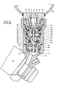
- FIG 3 shows a practical embodiment of the damping device according to the invention; in this Figure the elements bear the same references as the corresponding elements in Figure 1.
- the damper 14 is here independent of the stepped piston 9 and disposed in a bore of this piston.
- the damper 1 is supported on the shoulder of a spacer 29 and on a shim 30, itself supported on a shoulder of the frame 2. It is held by a nut 31 screwed onto a tubular extension 29 a of the spacer 29 which passes axially through the shock absorber 1. A nut 32 screwed into a thread in the frame 2 peripherally holds the shock absorber 1.
- the spacer 29 and its tubular extension 29 has comprise a stepped axial bore.
- valve 21 Inside the axial bore of the spacer is slidably mounted the valve 21 which is here a stepped valve. Its lower part, of small section, can close off the bore 23, while its upper part of large section slides in the axial bore of the spacer 29.
- This comprises peripheral orifices 33 which connect the chamber 7 above the damper 1 and the part of the hole in the spacer located opposite the lower part, of small section, of the valve 21.
- a second stepped spacer 34 can slide relative to the spacer 29 by deforming a seal 35 disposed between the two spacers 29 and 34. This seal is held by a nut 36. It seals between the chamber 7 and the chamber 37 located above the valve 21 and inside the spacers 29 and 34.
- the narrow part of the spacer 34 is crossed by an extension 38 of the valve 21, which has a collar 39 on which rests a lower cup 40 which transmits the force of the spring 22.
- This cup 40 has a bottom pierced with holes 41 for the free passage of the liquid.
- the spring 22 is supported on a top cup re 42 drilled peripherally with holes 43 and an axial hole 44.
- the upper cup 42 rests on a support 45 against which it is held in abutment by a nut 46 screwed into a thread of the frame 2.
- An O-ring 47 ensures the sealing between the support 45 and the frame 2.
- the stepped piston 9 can slide in the frame 2 and the support 45 by deforming the seals 48 and 49.
- the shoulder of the piston cooperates with the support 45 to define the chamber 12 directly supplied from the chamber 4 of the jack by the conduit 13 which could be inside or outside the frame 2.
- the second shock absorber 14 resting on a shoulder of the piston 9 is held peripherally by a nut 50 thus securing the shock absorber 14 and the piston 9.
- the shock absorber 14 has an axial hole traversed by an extension of the spacer 34 and by the extension 38 of the valve 21.
- a nut 51 screwed onto the extension of the spacer 34 keeps the damper 14 in abutment on an external shoulder of the spacer 34.
- the extension 38 of the valve 21 which passes through the narrow part of the spacer 34, allows the circulation of the liquid so that the liquid chamber 52 above the damper 14 extends inside the spacer 34 and from the upper part of the spacer 29 to the stage of large section ⁇ of the valve 21.
- This room 52 is in communication by the per slots 41 and 43 of the lower 40 and upper 42 cups with the accumulator 28 which is itself secured to the frame 2 by means of a nut 53 comprising an internal thread for connection to the accumulator and an external thread for connection to the frame 2.
- a calibrated hole 54 drilled in the stage of large section of the valve 21 allows the pressure balances between the upstream and downstream of the variable damper in the absence of flow.
- Figure 4 shows at 55 a the measured curve of the pressure difference P1 - P o as a function of the flow rate Q, for an oscillation frequency of 1Hz ; the curve 55 b is the curve for an oscillation frequency of 20 Hz. Due to the mobility of the damper 14, the curves 55 a and 55 b are close, which shows the good dynamic functioning of the device.
- variable damper which is particularly well suited to a hydropneumatic suspension, can be applied to any other device in which a displacement requires a flow of fluid.
Landscapes
- Engineering & Computer Science (AREA)
- General Engineering & Computer Science (AREA)
- Physics & Mathematics (AREA)
- Fluid Mechanics (AREA)
- Mechanical Engineering (AREA)
- Vehicle Body Suspensions (AREA)
- Fluid-Damping Devices (AREA)
Applications Claiming Priority (2)
| Application Number | Priority Date | Filing Date | Title |
|---|---|---|---|
| FR8614496A FR2605073B1 (fr) | 1986-10-14 | 1986-10-14 | Dispositif amortisseur variable automatique |
| FR8614496 | 1986-10-14 |
Publications (2)
| Publication Number | Publication Date |
|---|---|
| EP0264324A1 true EP0264324A1 (de) | 1988-04-20 |
| EP0264324B1 EP0264324B1 (de) | 1989-10-04 |
Family
ID=9339967
Family Applications (1)
| Application Number | Title | Priority Date | Filing Date |
|---|---|---|---|
| EP19870402220 Expired EP0264324B1 (de) | 1986-10-14 | 1987-10-07 | Automatisch regelbare Dämpfungsvorrichtung |
Country Status (3)
| Country | Link |
|---|---|
| EP (1) | EP0264324B1 (de) |
| DE (1) | DE3760685D1 (de) |
| FR (1) | FR2605073B1 (de) |
Cited By (3)
| Publication number | Priority date | Publication date | Assignee | Title |
|---|---|---|---|---|
| EP0346186A1 (de) * | 1988-06-08 | 1989-12-13 | Automobiles Peugeot | Hydropneumatische Aufhängungsvorrichtung und mit dieser Vorrichtung ausgestattetes Fahrzeug |
| EP0390670A1 (de) * | 1989-03-28 | 1990-10-03 | Automobiles Peugeot | Automatisch veränderliche Dämpfungsvorrichtung |
| WO2017137016A1 (en) * | 2016-02-11 | 2017-08-17 | Čvut V Praze, Fakulta Strojní | A method of control of a hydraulic damper damping force and a hydraulic damper |
Citations (4)
| Publication number | Priority date | Publication date | Assignee | Title |
|---|---|---|---|---|
| FR2088803A5 (de) * | 1970-04-24 | 1972-01-07 | Citroen Sa | |
| DE2230975A1 (de) * | 1971-06-22 | 1972-12-28 | Autoipari Kutato Intezet | Frequenzselektiver Schwingungsdämpfer für Kraftfahrzeuge |
| US3966030A (en) * | 1971-01-13 | 1976-06-29 | Jacques Sirven | Hydraulic shock absorber for vehicle suspension |
| DE3303293A1 (de) * | 1982-02-01 | 1984-01-05 | Kayaba Kogyo K.K., Tokyo | Daempfungskraft-regeleinrichtung uer teleskop-stossdaempfer |
Family Cites Families (2)
| Publication number | Priority date | Publication date | Assignee | Title |
|---|---|---|---|---|
| JPS58116210A (ja) * | 1981-12-28 | 1983-07-11 | Kayaba Ind Co Ltd | 積載量感応式シヨツクアブソ−バ |
| JPS60129443A (ja) * | 1983-12-14 | 1985-07-10 | Showa Mfg Co Ltd | 車両用油圧緩衝器 |
-
1986
- 1986-10-14 FR FR8614496A patent/FR2605073B1/fr not_active Expired - Fee Related
-
1987
- 1987-10-07 EP EP19870402220 patent/EP0264324B1/de not_active Expired
- 1987-10-07 DE DE8787402220T patent/DE3760685D1/de not_active Expired
Patent Citations (4)
| Publication number | Priority date | Publication date | Assignee | Title |
|---|---|---|---|---|
| FR2088803A5 (de) * | 1970-04-24 | 1972-01-07 | Citroen Sa | |
| US3966030A (en) * | 1971-01-13 | 1976-06-29 | Jacques Sirven | Hydraulic shock absorber for vehicle suspension |
| DE2230975A1 (de) * | 1971-06-22 | 1972-12-28 | Autoipari Kutato Intezet | Frequenzselektiver Schwingungsdämpfer für Kraftfahrzeuge |
| DE3303293A1 (de) * | 1982-02-01 | 1984-01-05 | Kayaba Kogyo K.K., Tokyo | Daempfungskraft-regeleinrichtung uer teleskop-stossdaempfer |
Non-Patent Citations (2)
| Title |
|---|
| PATENT ABSTRACTS OF JAPAN, vol. 7, no. 221 (M-246)[1366], 30 septembre 1983, page 156 M 246; & JP-A-58 116 210 (KAYABA KOGYO K.K.) 11-07-1983 * |
| PATENT ABSTRACTS OF JAPAN, vol. 9, no. 290 (M-430)[2013], 16 novembre 1985, page 76 M 430; & JP-A-60 129 443 (SHIYOUWA SEISAKUSHO) 10-07-1985 * |
Cited By (5)
| Publication number | Priority date | Publication date | Assignee | Title |
|---|---|---|---|---|
| EP0346186A1 (de) * | 1988-06-08 | 1989-12-13 | Automobiles Peugeot | Hydropneumatische Aufhängungsvorrichtung und mit dieser Vorrichtung ausgestattetes Fahrzeug |
| FR2632574A1 (fr) * | 1988-06-08 | 1989-12-15 | Peugeot | Dispositif de suspension hydropneumatique perfectionne et vehicule equipe de ce dispositif |
| EP0390670A1 (de) * | 1989-03-28 | 1990-10-03 | Automobiles Peugeot | Automatisch veränderliche Dämpfungsvorrichtung |
| FR2645079A1 (fr) * | 1989-03-28 | 1990-10-05 | Peugeot | Dispositif amortisseur variable automatique perfectionne |
| WO2017137016A1 (en) * | 2016-02-11 | 2017-08-17 | Čvut V Praze, Fakulta Strojní | A method of control of a hydraulic damper damping force and a hydraulic damper |
Also Published As
| Publication number | Publication date |
|---|---|
| FR2605073A1 (fr) | 1988-04-15 |
| FR2605073B1 (fr) | 1991-02-08 |
| DE3760685D1 (en) | 1989-11-09 |
| EP0264324B1 (de) | 1989-10-04 |
Similar Documents
| Publication | Publication Date | Title |
|---|---|---|
| FR2471873A1 (fr) | Dispositif de suspension de la caisse d'un vehicule permettant de regler la hauteur de ce vehicule au-dessus du sol par de faibles variations de la pression d'huile | |
| FR2711201A1 (fr) | Amortisseur à effet d'amortissement variable en fonction de la charge. | |
| FR2715203A1 (fr) | Amortisseur hydraulique réglable, pour véhicules automobiles. | |
| EP0750724A1 (de) | Regel- und modulierbare hydropneumatische dämpfungsvorrichtung | |
| FR2570457A1 (fr) | Amortisseur hydraulique reglable | |
| FR2651553A1 (fr) | Valve pour fluide hydraulique et amortisseur comportant une telle valve. | |
| EP0003290A1 (de) | Hydraulischer Dämpfer für Fahrzeugaufhängung | |
| FR2493256A1 (fr) | Fourche avant de motocyclette | |
| FR2868493A1 (fr) | Dispositif de suspension a amortisseur hydraulique a controle d'amortissement selectif | |
| EP2956687A1 (de) | Endlagendämpfungsvorrichtung | |
| FR2672654A1 (fr) | Auto-tenseur de courroie a poulie de tension et ressort de reglage. | |
| EP0264324B1 (de) | Automatisch regelbare Dämpfungsvorrichtung | |
| EP0278841B1 (de) | Aufhängung mit Federn verschiedener Art mit Höhenregelung und Dämpfungsregelung für eine Kraftfahrzeugachse | |
| FR2810951A1 (fr) | Dispositif de freinage d'un vehicule | |
| FR2914716A1 (fr) | Butee de compression hydraulique, notamment pour amortisseur hydraulique de suspension de vehicule automobile | |
| EP1554506A2 (de) | Hydraulischer anschlagpuffer für kraftfahrzeugstossdämpfer, stossdämpfendes system und verfahren zum betrieb eines solchen systems | |
| EP0244314B1 (de) | Schnell öffnendes Begrenzungsventil für hydropneumatisches Aufhängungselement für Schwerfahrzeug | |
| FR2507725A1 (fr) | Perfectionnements aux supports de suspension pour vehicules | |
| EP3997356B1 (de) | Hydraulischer endanschlag für einen dämpfer | |
| EP0346186B1 (de) | Hydropneumatische Aufhängungsvorrichtung und mit dieser Vorrichtung ausgestattetes Fahrzeug | |
| FR2573701A1 (fr) | Suspension pneumatique | |
| EP0262999B1 (de) | Lastabhängiges Bremsventil für Fahrzeuge | |
| FR2621663A1 (fr) | Amortisseur hydraulique du type a force d'amortissement reglable | |
| FR3047286B1 (fr) | Verin de suspension hydropneumatique de vehicule automobile et suspension de roue equipee d'un tel verin | |
| FR3134038A1 (fr) | Vehicule automobile comprenant un amortisseur ayant une butee inertielle integree |
Legal Events
| Date | Code | Title | Description |
|---|---|---|---|
| PUAI | Public reference made under article 153(3) epc to a published international application that has entered the european phase |
Free format text: ORIGINAL CODE: 0009012 |
|
| AK | Designated contracting states |
Kind code of ref document: A1 Designated state(s): DE GB IT |
|
| 17P | Request for examination filed |
Effective date: 19880316 |
|
| 17Q | First examination report despatched |
Effective date: 19880929 |
|
| GRAA | (expected) grant |
Free format text: ORIGINAL CODE: 0009210 |
|
| AK | Designated contracting states |
Kind code of ref document: B1 Designated state(s): DE GB IT |
|
| ITF | It: translation for a ep patent filed | ||
| GBT | Gb: translation of ep patent filed (gb section 77(6)(a)/1977) | ||
| REF | Corresponds to: |
Ref document number: 3760685 Country of ref document: DE Date of ref document: 19891109 |
|
| PLBE | No opposition filed within time limit |
Free format text: ORIGINAL CODE: 0009261 |
|
| STAA | Information on the status of an ep patent application or granted ep patent |
Free format text: STATUS: NO OPPOSITION FILED WITHIN TIME LIMIT |
|
| 26N | No opposition filed | ||
| PGFP | Annual fee paid to national office [announced via postgrant information from national office to epo] |
Ref country code: GB Payment date: 19911004 Year of fee payment: 5 |
|
| ITTA | It: last paid annual fee | ||
| PGFP | Annual fee paid to national office [announced via postgrant information from national office to epo] |
Ref country code: DE Payment date: 19911210 Year of fee payment: 5 |
|
| PG25 | Lapsed in a contracting state [announced via postgrant information from national office to epo] |
Ref country code: GB Effective date: 19921007 |
|
| GBPC | Gb: european patent ceased through non-payment of renewal fee |
Effective date: 19921007 |
|
| PG25 | Lapsed in a contracting state [announced via postgrant information from national office to epo] |
Ref country code: DE Effective date: 19930701 |
|
| PG25 | Lapsed in a contracting state [announced via postgrant information from national office to epo] |
Ref country code: IT Free format text: LAPSE BECAUSE OF NON-PAYMENT OF DUE FEES Effective date: 20051007 |