EP0264342A1 - Dispositif de fixation adjustable pour assembler deux parties de construction - Google Patents
Dispositif de fixation adjustable pour assembler deux parties de construction Download PDFInfo
- Publication number
- EP0264342A1 EP0264342A1 EP87630205A EP87630205A EP0264342A1 EP 0264342 A1 EP0264342 A1 EP 0264342A1 EP 87630205 A EP87630205 A EP 87630205A EP 87630205 A EP87630205 A EP 87630205A EP 0264342 A1 EP0264342 A1 EP 0264342A1
- Authority
- EP
- European Patent Office
- Prior art keywords
- hole
- component
- collar
- fastening device
- mounting element
- Prior art date
- Legal status (The legal status is an assumption and is not a legal conclusion. Google has not performed a legal analysis and makes no representation as to the accuracy of the status listed.)
- Granted
Links
- 238000010276 construction Methods 0.000 title description 2
- 230000005540 biological transmission Effects 0.000 claims abstract description 13
- 239000002184 metal Substances 0.000 claims abstract description 9
- 230000002093 peripheral effect Effects 0.000 claims description 8
- 239000004033 plastic Substances 0.000 description 7
- 230000003313 weakening effect Effects 0.000 description 3
- 238000009434 installation Methods 0.000 description 2
- 238000005553 drilling Methods 0.000 description 1
- 239000007769 metal material Substances 0.000 description 1
- 238000000034 method Methods 0.000 description 1
- 239000002990 reinforced plastic Substances 0.000 description 1
- 230000000284 resting effect Effects 0.000 description 1
Images
Classifications
-
- F—MECHANICAL ENGINEERING; LIGHTING; HEATING; WEAPONS; BLASTING
- F16—ENGINEERING ELEMENTS AND UNITS; GENERAL MEASURES FOR PRODUCING AND MAINTAINING EFFECTIVE FUNCTIONING OF MACHINES OR INSTALLATIONS; THERMAL INSULATION IN GENERAL
- F16B—DEVICES FOR FASTENING OR SECURING CONSTRUCTIONAL ELEMENTS OR MACHINE PARTS TOGETHER, e.g. NAILS, BOLTS, CIRCLIPS, CLAMPS, CLIPS OR WEDGES; JOINTS OR JOINTING
- F16B5/00—Joining sheets or plates, e.g. panels, to one another or to strips or bars parallel to them
- F16B5/02—Joining sheets or plates, e.g. panels, to one another or to strips or bars parallel to them by means of fastening members using screw-thread
- F16B5/0283—Joining sheets or plates, e.g. panels, to one another or to strips or bars parallel to them by means of fastening members using screw-thread with an externally threaded sleeve around the neck or the head of the screw-threaded element for adjustably fastening a plate or frame or the like to a fixed element
-
- E—FIXED CONSTRUCTIONS
- E06—DOORS, WINDOWS, SHUTTERS, OR ROLLER BLINDS IN GENERAL; LADDERS
- E06B—FIXED OR MOVABLE CLOSURES FOR OPENINGS IN BUILDINGS, VEHICLES, FENCES OR LIKE ENCLOSURES IN GENERAL, e.g. DOORS, WINDOWS, BLINDS, GATES
- E06B1/00—Border constructions of openings in walls, floors, or ceilings; Frames to be rigidly mounted in such openings
- E06B1/56—Fastening frames to the border of openings or to similar contiguous frames
- E06B1/60—Fastening frames to the border of openings or to similar contiguous frames by mechanical means, e.g. anchoring means
- E06B1/6069—Separate spacer means acting exclusively in the plane of the opening; Shims; Wedges; Tightening of a complete frame inside a wall opening
- E06B1/6076—Separate spacer means acting exclusively in the plane of the opening; Shims; Wedges; Tightening of a complete frame inside a wall opening of screw-type
Definitions
- the present invention relates to an adjustable fastening device, preferably made of metal, for joining two components together, with a mounting element that can be installed in an adapted hole in the component on the side of the component that is opposite the component, the mounting element being provided with an internal thread is and has a collar, with a force transmission element which is at least partially provided with an external thread and can be screwed into the mounting element and has a through hole with a stop or the like at one end, the hole being otherwise wholly or partly designed with a polygonal cross section and the support element consists of a relatively narrow sleeve-like ring.
- adjustable fastening devices in particular for mounts, windows, doors, frames or the like in the corresponding openings in buildings, etc.
- GB-PS No. 1 244 498 a fastening device by means of which the position of the window frame relative to the surrounding building can be precisely adjusted and the window frame can be fastened to the building at the same time.
- the adjustable fastening element according to this patent is essentially characterized in that it consists of an externally threaded pin which is adjustably inserted into a hole in the window frame provided with through threads. The threaded pin protrudes from the side surface of the window frame facing the surrounding structure, and when the frame is installed, the pin end lies against the structure mentioned.
- the peg has a central through hole through which a nail is finally passed in order to be driven into the surrounding structure.
- the peg and thus the window frame is finally attached to the surrounding building.
- the hole provided with continuous threads simply consists of a threaded hole in the window frame itself or of an internally threaded one provided lining inserted in the window frame.
- NO Patent No. 151.383 describes a fastening element that largely prevents the weakening of the window frame by large through holes.
- This fastener also withstands the high forces that occur when adjusting it.
- This fastening element is of the type which comprises a holding element which is installed in a corresponding recess in the side surface of the frame or frame facing the building. A hole with a relatively small diameter leads from the mentioned recess to the opposite side surface of the border or the frame.
- the mounting element has a through hole provided with an internal thread.
- the fastening element also consists of a pressure element which is partially threaded on the outside and has a through hole.
- a screw or similar fastener is used to fasten the fastener to the building.
- Be the fastening element is essentially characterized in that it also consists of a locking ring for fixing the mounting element in the frame or the like, and that the inner hole of the pressure element has a stop in the lowermost part closest to the construction, and that the hole in the rest is wholly or partially formed with a polygonal cross section.
- Fastening element described in 151.383 consists of the part of the mounting element which lies completely inside the recess from a head and the locking ring surrounding the mounting element is slotted in the innermost area.
- the pressure element i.e. the externally threaded pin, the head of which rests against the surface of the opening in the building, is normally fastened to the building by means of a screw, the screw head resting on a stop located so far inside the through inner hole of the pressure element that the part the hole that remains against the inside of the frame or frame remains free when the screw is installed.
- the last section of the hole is used to insert a tool with which the pressure element can be rotated and adjusted after loosening the screw mentioned.
- the fastening device described in NO-PS 151.383 is among others. necessary to cut two holes in the frame, i.e. a hole to create the relatively narrow through hole mentioned in the frame, and a second hole to create a wider recess for receiving said bracket member with the locking ring surrounding it.
- a hole to create the relatively narrow through hole mentioned in the frame i.e. a hole to create the relatively narrow through hole mentioned in the frame
- a second hole to create a wider recess for receiving said bracket member with the locking ring surrounding it.
- the wider recess in the frame which is intended to accommodate the mounting element, causes a certain weakening of the frame itself.
- the holding element consists of a metallic material and is designed such that it automatically locks in one of the components when it is installed in the through hole mentioned. Due to the design of the mounting element made of metal, such a thin-walled dimension can be selected that the mounting element directly into the relatively narrow through hole in which a component can be inserted. This eliminates the locking ring, which is required according to NO-PS 151.383.
- the adjustable fastening device is preferably made of metal. It consists of a mounting element, which is installed in an adapted through hole in one of two components to be joined on the side of the one component that faces the other component.
- the mounting element is provided with an internal thread.
- the fastening device also consists of a force transmission element, which is partially provided with an external thread, in order to be screwed into the mentioned holding element.
- the force transmission element has a through hole, which has a stop for a screw head or the like at one end, wherein the rest of the hole can be designed in whole or in part with a polygonal cross section.
- the mounting element consists of a relatively narrow sleeve-like ring, from which a plurality of tongue-like or ear-like parts protrude, which lock the mounting element on a component.
- the fastening device is essentially characterized in that the tongue-like or ear-like parts have corrugated edge surfaces and are somewhat inclined to the vertical center line of the sleeve-like ring mentioned.
- the object of the invention is to provide an adjustable fastening device of the type mentioned at the outset which is suitable for surrounds, frames and the like consisting of such hollow profiles.
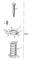
- the holding element provided with an internal thread has an axially protruding from its peripheral surface Distance from the collar arranged lip and a tab opposite in the plane of the collar of the lip with a hole.
- the holding element 2 consists of a sleeve-like ring 6 with a collar 8 and a lip 12 which projects radially from the peripheral surface 10 of the ring 6 and which is part of a part 14 which extends axially from the plane of the collar 8 along the peripheral surface 10 of the ring 6.
- the mounting element 2 is provided with an internal thread.
- the collar 8 merges on the side diametrically opposite the lip 12 into a tab 16 in which a hole 18 is provided.
- the power transmission element 4 has a through hole 10, which is polygonal at least at its upper end in FIG. 1, and which also has a polygonal head 22 at the other lower end in FIG. 1.
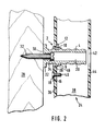
- the holding element 2 is installed in a hole 26 in the component 24.
- the force transmission element 4 is screwed into the mounting element 2 and lies with its head 22 against the second component 28.
- a raised circular edge 30 engages with the component 24.
- the force transmission element is fixed to component 24 by means of a screw 32.
- the head of the screw 32 lies in the hole 20 of the power transmission element 4 against a stop 34.
- the fastening device consisting of the two parts is inserted into the drilled hole 26 in the component 24, so that the lip 12 slides under the profile wall 36 of the hollow profile 38 and the collar 8 and the tab 16 on the wall 36 lie on.
- the tab 16 is screwed to the hollow profile by means of a screw 40. If the component 24 is to be joined to the component 28 later, a rotation of the force transmission element 4 is required. During this rotation, force is transmitted to the mounting element 2, and the tab 16 and the screw 40 prevent the mounting element from rotating in the hole 26.
- a hole 42 is provided on the profile wall 44 in order to be able to insert a tool into the hole 20 of the force transmission element 4 in order to rotate the same.
- the screw 32 can be screwed tight.
- the lip 12 and the tab 16 with the screw 40 serve to absorb the forces occurring when the component 24 is fastened to the component 28 with the device according to the invention in the axial direction thereof.
- a tongue 46 is punched out of the tab 16 and bent against the peripheral surface 10 of the ring 6. Because the hole 26 in the component 24 has to be drilled somewhat larger than the diameter of the ring 6 because of the L-shaped part 14, the tongue 46 diametrically opposite the L-shaped part 14 stabilizes the mounting element in the hole 26. It is quite conceivable that the lip 12 is formed on the peripheral surface 10; then the tongue 46 is unnecessary, at least in the case of thin-walled hollow profiles.
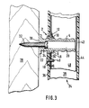
- FIG. 3. 2 differs from FIG. 1 only by the hollow profile 48 made of metal.
- the screw 40 also serves here for the screwing of the hollow metal profile and the hollow plastic profile, which is common in reinforced plastic hollow profiles. Since there is a slight play between the two hollow profiles, the lip 12 engages between the two hollow profiles.
Landscapes
- Engineering & Computer Science (AREA)
- General Engineering & Computer Science (AREA)
- Mechanical Engineering (AREA)
- Civil Engineering (AREA)
- Structural Engineering (AREA)
- Connection Of Plates (AREA)
- Analysing Materials By The Use Of Radiation (AREA)
- Investigating Or Analysing Biological Materials (AREA)
- Bolts, Nuts, And Washers (AREA)
- Paper (AREA)
- Control Of Motors That Do Not Use Commutators (AREA)
Priority Applications (1)
| Application Number | Priority Date | Filing Date | Title |
|---|---|---|---|
| AT87630205T ATE53630T1 (de) | 1986-10-17 | 1987-10-15 | Einstellbare befestigungsvorrichtung zum zusammenfuegen von zwei bauteilen. |
Applications Claiming Priority (2)
| Application Number | Priority Date | Filing Date | Title |
|---|---|---|---|
| LU86631A LU86631A1 (de) | 1986-10-17 | 1986-10-17 | Einstellbare befestigungsvorrichtung zum zusammenfuegen von zwei bauteilen |
| LU86631 | 1986-10-17 |
Publications (2)
| Publication Number | Publication Date |
|---|---|
| EP0264342A1 true EP0264342A1 (fr) | 1988-04-20 |
| EP0264342B1 EP0264342B1 (fr) | 1990-06-13 |
Family
ID=19730798
Family Applications (1)
| Application Number | Title | Priority Date | Filing Date |
|---|---|---|---|
| EP87630205A Expired - Lifetime EP0264342B1 (fr) | 1986-10-17 | 1987-10-15 | Dispositif de fixation adjustable pour assembler deux parties de construction |
Country Status (6)
| Country | Link |
|---|---|
| US (1) | US4846622A (fr) |
| EP (1) | EP0264342B1 (fr) |
| AT (1) | ATE53630T1 (fr) |
| DE (1) | DE3763216D1 (fr) |
| DK (1) | DK164673C (fr) |
| LU (1) | LU86631A1 (fr) |
Cited By (5)
| Publication number | Priority date | Publication date | Assignee | Title |
|---|---|---|---|---|
| NL9002387A (nl) * | 1990-11-01 | 1992-06-01 | Nijhuis Alkono B V | Element, systeem en werkwijze ter bevestiging van een paneelconstructie aan een steunconstructie. |
| FR2680208A1 (fr) * | 1991-08-09 | 1993-02-12 | Rehau Sa | Cale reglable. |
| GB2293425A (en) * | 1994-09-22 | 1996-03-27 | Allen William Edmondson | Fixing anchors,e.g.for window or door frames |
| WO2008012207A1 (fr) * | 2006-07-28 | 2008-01-31 | BSH Bosch und Siemens Hausgeräte GmbH | Système de fixation pour appareils domestiques |
| DE102006002262B4 (de) * | 2006-01-17 | 2024-06-06 | Robert Bosch Gmbh | Warmwassergerät |
Families Citing this family (19)
| Publication number | Priority date | Publication date | Assignee | Title |
|---|---|---|---|---|
| US6095736A (en) * | 1997-10-28 | 2000-08-01 | Nissi Industrial Technology, Inc. | Self-contained fastener device |
| US6652208B2 (en) * | 1999-04-08 | 2003-11-25 | Macdonald Joseph Gillis | Fastener device and method for attaching a panel of semi-rigid material to a substrate |
| US6669425B1 (en) * | 2002-03-25 | 2003-12-30 | John Preta | Self-threading fastener for connecting an article to a surface upon movement of the article towards the fastener |
| FR2864986B1 (fr) * | 2004-01-14 | 2006-04-28 | Ind De Moules Et Moulages Plas | Dispositif de fixation pour la pose de menuiseries sur dormants existants |
| US9272378B1 (en) | 2005-07-12 | 2016-03-01 | Elijah Tooling, Inc. | System for holding working objects |
| US8770902B1 (en) | 2005-07-12 | 2014-07-08 | Elijah Tooling, Inc. | Precision locating fastening system |
| USD745371S1 (en) | 2013-03-27 | 2015-12-15 | Joseph TROJANOWSKI | Receptacle cover |
| US9728947B2 (en) | 2012-08-30 | 2017-08-08 | Joseph TROJANOWSKI | Screwless and seamless cover plate and cover plate assemblies for electrical fixtures |
| US9711957B2 (en) | 2012-08-30 | 2017-07-18 | Joseph TROJANOWSKI | Screwless and seamless cover plate and cover plate assemblies that comprise one or more retention members that selectively engage and substantially conform to the outer surface and edges of an electrical outlet or switch, or audio, data, or video plug, cable, or connector, to releasably secure the cover plate sub-assembly thereto |
| USD878183S1 (en) | 2013-03-27 | 2020-03-17 | Joseph TROJANOWSKI | Receptacle cover comprising attachment clips |
| US9702388B2 (en) | 2014-08-08 | 2017-07-11 | Joseph TROJANOWSKI | Axially adjustable threaded mounting snap fit connector |
| US10596673B1 (en) | 2015-11-18 | 2020-03-24 | Elijah Tooling, Inc. | Modular pressure application system |
| US11666997B1 (en) | 2015-11-18 | 2023-06-06 | Elijah Tooling, Inc. | Precision locating fastening device |
| DE102019110201A1 (de) * | 2019-04-17 | 2020-10-22 | Witte Automotive Gmbh | Toleranzausgleichsvorrichtung |
| US20220065281A1 (en) * | 2020-09-03 | 2022-03-03 | Milbank Manufacturing Co. | Plumb adjuster for electrical enclosure |
| US12371941B2 (en) * | 2022-03-11 | 2025-07-29 | Charles James SPOFFORD | Self-aligning jamb jack screw with partial sphere |
| US12173516B2 (en) * | 2022-03-11 | 2024-12-24 | Charles James SPOFFORD | Self-aligning jamb jack screw |
| CN117628033A (zh) * | 2022-08-17 | 2024-03-01 | 伊利诺斯工具制品有限公司 | 紧固组件及包括该紧固组件的紧固系统 |
| US12534951B1 (en) | 2025-04-22 | 2026-01-27 | Charles James SPOFFORD | Threaded, booming, cylindrical shims |
Citations (7)
| Publication number | Priority date | Publication date | Assignee | Title |
|---|---|---|---|---|
| GB1244498A (en) * | 1967-11-14 | 1971-09-02 | Le Laminage A Froid S A | Improvements in or relating to window or door frames |
| US3992833A (en) * | 1974-06-05 | 1976-11-23 | Josef Hulinsky | Apparatus for mounting a window or a door frame |
| US4038801A (en) * | 1975-01-03 | 1977-08-02 | Busch Guenter | Device for connecting parts on walls and ceilings |
| DE3320297A1 (de) * | 1983-06-04 | 1984-12-06 | Arnold 7918 Illertissen Butzbach | Vorrichtung zur befestigung eines fensterrahmens |
| NO151383B (no) * | 1983-02-01 | 1984-12-17 | Hamax As | Anordning ved spalteventil |
| GB2145184A (en) * | 1983-08-16 | 1985-03-20 | Hamax As | Adjustable fasteners for door or window frames |
| DE8601106U1 (de) * | 1985-02-13 | 1986-03-06 | Edvardsen, Terje, Fredrikstad | Einstellbare Befestigungsvorrichtung zum Zusammenfügen von zwei Bauteilen |
Family Cites Families (5)
| Publication number | Priority date | Publication date | Assignee | Title |
|---|---|---|---|---|
| US2443343A (en) * | 1945-08-06 | 1948-06-15 | Mcinerney Plastics Company | Mounting |
| US2516274A (en) * | 1947-07-17 | 1950-07-25 | Tinnerman Products Inc | Fastening device |
| US2552782A (en) * | 1948-12-22 | 1951-05-15 | United Carr Fastener Corp | Nut fastener |
| US3217772A (en) * | 1964-04-17 | 1965-11-16 | Bishop & Babcock Corp | Front end mounting cage nut fastener |
| US3424212A (en) * | 1967-04-12 | 1969-01-28 | United Co The | Screw wrench device |
-
1986
- 1986-10-17 LU LU86631A patent/LU86631A1/de unknown
-
1987
- 1987-10-09 US US07/107,266 patent/US4846622A/en not_active Expired - Fee Related
- 1987-10-15 EP EP87630205A patent/EP0264342B1/fr not_active Expired - Lifetime
- 1987-10-15 DE DE8787630205T patent/DE3763216D1/de not_active Expired - Lifetime
- 1987-10-15 AT AT87630205T patent/ATE53630T1/de not_active IP Right Cessation
- 1987-10-16 DK DK540387A patent/DK164673C/da not_active IP Right Cessation
Patent Citations (7)
| Publication number | Priority date | Publication date | Assignee | Title |
|---|---|---|---|---|
| GB1244498A (en) * | 1967-11-14 | 1971-09-02 | Le Laminage A Froid S A | Improvements in or relating to window or door frames |
| US3992833A (en) * | 1974-06-05 | 1976-11-23 | Josef Hulinsky | Apparatus for mounting a window or a door frame |
| US4038801A (en) * | 1975-01-03 | 1977-08-02 | Busch Guenter | Device for connecting parts on walls and ceilings |
| NO151383B (no) * | 1983-02-01 | 1984-12-17 | Hamax As | Anordning ved spalteventil |
| DE3320297A1 (de) * | 1983-06-04 | 1984-12-06 | Arnold 7918 Illertissen Butzbach | Vorrichtung zur befestigung eines fensterrahmens |
| GB2145184A (en) * | 1983-08-16 | 1985-03-20 | Hamax As | Adjustable fasteners for door or window frames |
| DE8601106U1 (de) * | 1985-02-13 | 1986-03-06 | Edvardsen, Terje, Fredrikstad | Einstellbare Befestigungsvorrichtung zum Zusammenfügen von zwei Bauteilen |
Cited By (5)
| Publication number | Priority date | Publication date | Assignee | Title |
|---|---|---|---|---|
| NL9002387A (nl) * | 1990-11-01 | 1992-06-01 | Nijhuis Alkono B V | Element, systeem en werkwijze ter bevestiging van een paneelconstructie aan een steunconstructie. |
| FR2680208A1 (fr) * | 1991-08-09 | 1993-02-12 | Rehau Sa | Cale reglable. |
| GB2293425A (en) * | 1994-09-22 | 1996-03-27 | Allen William Edmondson | Fixing anchors,e.g.for window or door frames |
| DE102006002262B4 (de) * | 2006-01-17 | 2024-06-06 | Robert Bosch Gmbh | Warmwassergerät |
| WO2008012207A1 (fr) * | 2006-07-28 | 2008-01-31 | BSH Bosch und Siemens Hausgeräte GmbH | Système de fixation pour appareils domestiques |
Also Published As
| Publication number | Publication date |
|---|---|
| ATE53630T1 (de) | 1990-06-15 |
| DK540387D0 (da) | 1987-10-16 |
| DK164673C (da) | 1992-12-14 |
| DE3763216D1 (de) | 1990-07-19 |
| DK164673B (da) | 1992-07-27 |
| DK540387A (da) | 1988-04-18 |
| EP0264342B1 (fr) | 1990-06-13 |
| US4846622A (en) | 1989-07-11 |
| LU86631A1 (de) | 1987-04-02 |
Similar Documents
| Publication | Publication Date | Title |
|---|---|---|
| EP0264342B1 (fr) | Dispositif de fixation adjustable pour assembler deux parties de construction | |
| DE69707679T2 (de) | Schraube für kortikalknochen | |
| DE2243661C3 (de) | Vorrichtung zum Befestigen einer Platte an einem Bauteil, insbesondere von Verkleidungsplatten im Flugzeugbau | |
| EP0691478B1 (fr) | Dispositif de fixation pour une ferrure ayant un alésage, en particulier pour un élément de charnière | |
| DE8601106U1 (de) | Einstellbare Befestigungsvorrichtung zum Zusammenfügen von zwei Bauteilen | |
| DE60302835T2 (de) | Halteöse für Schrauben | |
| DE69006170T2 (de) | Schraubdübel, insbesondere für weiches Material, und dafür geeignetes Werkzeug. | |
| DE19816533C2 (de) | Vorrichtung zur Befestigung einer Innenverkleidung für Fahrzeuge | |
| EP1857607A2 (fr) | Elément et méthode de fixation de panneaux isolants | |
| DE4414765C2 (de) | Schraubbefestigung | |
| EP0846878B1 (fr) | Fixation pour matériau isolant | |
| EP1296069A2 (fr) | Assemblage vissé étanche, réglable et autofreiné | |
| EP0019782A2 (fr) | Cheville métallique creuse | |
| EP2971400B1 (fr) | Douille et élément de fixation pour fixer une couche de matériau | |
| EP0754827B1 (fr) | Dispositif pour la fixation amovible et axialement non coulissante d'une poignée sur un élément de palier, notamment pour une poignée de porte ou fenêtre | |
| DE19543651C2 (de) | Spreizbares Befestigungselement zum Befestigen oder Verbinden von Teilen | |
| LU86872A1 (de) | Einstellbare befestigungsvorrichtung zum zusammenfuegen von zwei bauteilen | |
| EP3567264B1 (fr) | Système de fixation | |
| EP0905425B1 (fr) | Dispositif de fixation | |
| DE4021245C2 (fr) | ||
| DE4033650A1 (de) | Gewindeeinsatz | |
| DE10008828A1 (de) | Flexibles Montage- und Befestigungssystem | |
| EP0155484B1 (fr) | Cheville à expansion | |
| DE102008040687A1 (de) | Verankerungselement | |
| DE19647209C2 (de) | Befestigungsvorrichtung aus Kunststoff |
Legal Events
| Date | Code | Title | Description |
|---|---|---|---|
| PUAI | Public reference made under article 153(3) epc to a published international application that has entered the european phase |
Free format text: ORIGINAL CODE: 0009012 |
|
| AK | Designated contracting states |
Kind code of ref document: A1 Designated state(s): AT DE GB SE |
|
| 17P | Request for examination filed |
Effective date: 19880520 |
|
| 17Q | First examination report despatched |
Effective date: 19890508 |
|
| GRAA | (expected) grant |
Free format text: ORIGINAL CODE: 0009210 |
|
| AK | Designated contracting states |
Kind code of ref document: B1 Designated state(s): AT DE GB SE |
|
| REF | Corresponds to: |
Ref document number: 53630 Country of ref document: AT Date of ref document: 19900615 Kind code of ref document: T |
|
| GBT | Gb: translation of ep patent filed (gb section 77(6)(a)/1977) | ||
| REF | Corresponds to: |
Ref document number: 3763216 Country of ref document: DE Date of ref document: 19900719 |
|
| PLBE | No opposition filed within time limit |
Free format text: ORIGINAL CODE: 0009261 |
|
| STAA | Information on the status of an ep patent application or granted ep patent |
Free format text: STATUS: NO OPPOSITION FILED WITHIN TIME LIMIT |
|
| 26N | No opposition filed | ||
| PGFP | Annual fee paid to national office [announced via postgrant information from national office to epo] |
Ref country code: GB Payment date: 19910808 Year of fee payment: 5 |
|
| PGFP | Annual fee paid to national office [announced via postgrant information from national office to epo] |
Ref country code: DE Payment date: 19910916 Year of fee payment: 5 |
|
| PGFP | Annual fee paid to national office [announced via postgrant information from national office to epo] |
Ref country code: SE Payment date: 19910923 Year of fee payment: 5 |
|
| PGFP | Annual fee paid to national office [announced via postgrant information from national office to epo] |
Ref country code: AT Payment date: 19910926 Year of fee payment: 5 |
|
| REG | Reference to a national code |
Ref country code: GB Ref legal event code: 732 |
|
| PG25 | Lapsed in a contracting state [announced via postgrant information from national office to epo] |
Ref country code: GB Effective date: 19921015 Ref country code: AT Effective date: 19921015 |
|
| PG25 | Lapsed in a contracting state [announced via postgrant information from national office to epo] |
Ref country code: SE Effective date: 19921016 |
|
| GBPC | Gb: european patent ceased through non-payment of renewal fee |
Effective date: 19921015 |
|
| PG25 | Lapsed in a contracting state [announced via postgrant information from national office to epo] |
Ref country code: DE Effective date: 19930701 |
|
| EUG | Se: european patent has lapsed |
Ref document number: 87630205.0 Effective date: 19930510 |