EP0264465B1 - Méthode et appareil pour la fabrication d'un tube revêtu - Google Patents
Méthode et appareil pour la fabrication d'un tube revêtu Download PDFInfo
- Publication number
- EP0264465B1 EP0264465B1 EP19860114406 EP86114406A EP0264465B1 EP 0264465 B1 EP0264465 B1 EP 0264465B1 EP 19860114406 EP19860114406 EP 19860114406 EP 86114406 A EP86114406 A EP 86114406A EP 0264465 B1 EP0264465 B1 EP 0264465B1
- Authority
- EP
- European Patent Office
- Prior art keywords
- tube
- glass tube
- thermoplastic
- metallic
- heating
- Prior art date
- Legal status (The legal status is an assumption and is not a legal conclusion. Google has not performed a legal analysis and makes no representation as to the accuracy of the status listed.)
- Expired
Links
Images


Classifications
-
- C—CHEMISTRY; METALLURGY
- C23—COATING METALLIC MATERIAL; COATING MATERIAL WITH METALLIC MATERIAL; CHEMICAL SURFACE TREATMENT; DIFFUSION TREATMENT OF METALLIC MATERIAL; COATING BY VACUUM EVAPORATION, BY SPUTTERING, BY ION IMPLANTATION OR BY CHEMICAL VAPOUR DEPOSITION, IN GENERAL; INHIBITING CORROSION OF METALLIC MATERIAL OR INCRUSTATION IN GENERAL
- C23D—ENAMELLING OF, OR APPLYING A VITREOUS LAYER TO, METALS
- C23D5/00—Coating with enamels or vitreous layers
- C23D5/04—Coating with enamels or vitreous layers by dry methods
-
- C—CHEMISTRY; METALLURGY
- C03—GLASS; MINERAL OR SLAG WOOL
- C03C—CHEMICAL COMPOSITION OF GLASSES, GLAZES OR VITREOUS ENAMELS; SURFACE TREATMENT OF GLASS; SURFACE TREATMENT OF FIBRES OR FILAMENTS MADE FROM GLASS, MINERALS OR SLAGS; JOINING GLASS TO GLASS OR OTHER MATERIALS
- C03C27/00—Joining pieces of glass to pieces of other inorganic material; Joining glass to glass other than by fusing
- C03C27/02—Joining pieces of glass to pieces of other inorganic material; Joining glass to glass other than by fusing by fusing glass directly to metal
Definitions
- This invention relates to a method for the manufacture of a clad tube having glass, for example, tightly superposed in a layer on the inner side of a metallic tube such as a steel pipe, an apparatus for the manufacture of the clad tube, and a method for the operation of the apparatus mentioned above.
- a method of producing a clad tube with a glass tube and a steel tube which comprises heating the steel tube and the tube inserted through the steel tube in a heating oven filled with an atmosphere formed by combustion of gas or heavy oil thereby softening the glass tube and then applying heat on the interior of the glass tube thereby causing the glass tube to be inflated and fused with the inner side of the steel tube is well known.
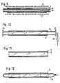
- FIG. 12 illustrates in detail a typical conventional method for the manufacture of a clad tube with a glass tube and a steel tube.
- 31 denotes a glass tube having one end thereof closed and the other end thermally formed in the shape of a nozzle to facilitate application of pressure of air therethrough
- 2 denotes a tube of steel such as stainless steel disposed around the outer side of the aforementioned glass tube 31.
- the steel tube 2 and the glass tube 31 are heated in the oven filled with the aforementioned atmosphere, then the softened glass tube 31 is pressed outwardly from the inner side thereof with the pressure applied through the nozzle of the glass tube thereby to fuse the glass tube 31 with the inner side of the steel tube 2, to complete a clad tube.
- the glass tube 31 has been formed by first molding molten glass in the shape of a pipe with a special die, cutting the pipe to a prescribed length, then reheating the opposite ends of the cut pipe, and forming the opposite ends severally in prescribed shapes.
- a glass tube having two openings at its opposite ends is used, said openings being tightly closed by sealing means.
- This invention has been made to overcome the drawbacks of the prior art mentioned above. It aims to provide a method for the manufacture of a clad tube which requires only a short heating time and consequently enjoys enhanced productivity, permits easy temperature control, and enables the finished product to exhibit satisfactory performance owing to thorough elimination of bubbles, an apparatus for the manufacture of the clad tube, and a method for the operation of the apparatus.
- thermoplastic tube consisting of a thermoplastic tube and a metallic tube, characterized by coaxially inserting into a cylindrical induction coil a metallic tube and a thermoplastic tube of greater length than the metallic tube, inserted through said metallic tube, said thermoplastic tube having two openings at its opposite ends which are tightly closed, allowing said metallic tube to be heated by said induction coil serving as a heater, and heating said thermoplastic tube with the radiant heat from said heater and, at the same time, applying pressure on the interior of said thermoplastic tube, thereby causing said thermoplastic tube to be inflated and fused with the inner surface of said metallic tube.
- thermoplastic tube consisting of a thermoplastic tube and a metallic tube consisting of a thermoplastic tube and a metallic tube
- a method for the manufacture of a clad tube consisting of a thermoplastic tube and a metallic tube consisting of a thermoplastic tube and a metallic tube comprising tightly closing a thermoplastic tube inserted through a metallic tube and having openings at the opposite ends thereof and being of greater length than the metallic tube, characterised by indirectly heating said thermoplastic tube by said metallic tube which is induction heated and, either after of during the course of said heating, applying pressure to the interior of said thermoplastic tube, thereby causing said thermoplastic tube to be inflated and fused with the inner surface of said metallic tube.
- an apparatus for carrying out the method of the present invention comprising means for tightly closing openings at the opposite ends of a thermoplastic tube inserted through a metallic tube, pressure means for applying pressure to the interior of said thermoplastic tube, and induction heating means for indirectly heating said metallic tube.
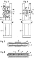
- Figure 1 depicts one working example of the present invention.
- a tube 2 of steel such as stainless steel is inserted through the interior of an induction coil 1 and, at the same time, a glass tube 3 is inserted through the interior of the steel tube 2 and these three components 1, 2 and 3 are coaxially supported in position.
- an electric current of high frequency in the order of 1,800 Hz is passed through the induction coil 1
- an induced electric current flows through the steel tube 2 disposed inside the induction coil.
- the steel tube 2 generates heat.
- the glass tube 3 inserted through the steel tube 2 now serving as a heater is heated with the radiant heat from the steel tube 2 as the heater.
- Figure 2 illustrates a typical apparatus for the manufacture of a clad tube by the use of the afore- mentioned induction coil.
- the parts which have equivalents in Figure 1 are denoted by the same reference numerals.
- A denotes an apparatus and 1 denotes a cylindrical heating induction coil disposed in the heating part of the apparatus and supported in a horizontal direction with a suitable member on a frame B erected on the apparatus A.
- a skid rail 4 adapted to facilitate the insertion and extraction of the steel tube 2, a member to be heated, and of the glass tube 3 inserted through this steel tube 2, is disposed in a horizontal direction.
- the outside diameter of this glass tube 3 is slightly smaller than the inside diameter of the steel tube 2 so that the glass tube 3 may be inserted into the afore-mentioned steel tube 2.
- This glass tube 3 has a length greater than the length of the steel tube 2.
- This length of the glass tube 3 is such that when the glass tube is inserted in the induction coil 1, the glass tube 3 will protrude to a prescribed length from each of the opposite ends of a heater of the apparatus.
- Reference numerals 5 and 6 denote a stationary cap and a movable cap for tightly closing the opposite ends of the glass tube 3 and supporting the glass tube 3 in position.
- the stationary cap 5 is attached to a movable bracket 12 (see figure 4) rotating about a shaft 11 on the frame B on the righthand side relative to the diagram of the apparatus A at a position substantially coinciding with the axis of the induction coil 1.
- the movable cap 6 is disposed on the left side of the diagram, of the apparatus at a position opposite the stationary cap 5, connected to the leading end of a piston 7a of a pneumatic cylinder 7 secured on a frame D, and enabled to be moved in a horizontal direction in consequence of the movement of the piston 7a of the cylinder 7.
- the end parts of this glass tube 3 are fixed in position by the stationary cap 5 and the movable cap 6 by means of respective packings 5a and 6a.
- a nozzle 6b for applying pressure to the interior of the glass tube 3 is provided on the movable cap by means of a packing 6a.
- 8 and 9 are clamps disposed respectively near the packings 5a and 6a and each formed of an upper arm 8b (9b) and a lower arm 8a (9a).
- the arms 8a and 8b are opened or closed by cylinders 8c and 8d fixed on the frame.
- a force is uniformly exerted radially towards the center of the glass tube 3 by means of a stationary member 10 so as to prevent the glass tube from being displaced in the horizontal direction.
- the clamp 9 on the lefthand side is provided with a similar cylinder, though not shown in the diagrams.
- the bracket 12 is turned about shaft 11 out of the surface of the drawing of Figure 4 and the steel tube 2 is mounted on the skid rail 4 at the central position inside the induction coil 1 so that the steel tube 4 may be uniformly heated throughout the entire volume thereof, with heat sufficiently distributed even to the opposite end parts thereof.
- the glass tube 3 is inserted through the interior of the steel tube 2.
- the movable cap 6 side of the glass tube 3 is allowed to protrude to a slightly greater distance than the opposite side thereof.
- the axis of the glass tube 3 and the axis of the induction coil 1 are made to coincide substantially with each other by the clamps 8 and 9.
- the clamps 8 and 9 are tightened around the glass tube 3 to such an extent that the glass tube 3 may be readily moved by the force exerted in the axial direction from the movable cap 6 side.
- the bracket 12 is turned about shaft 11 so that the righthand end of the glass tube 3 fits into the inner surface side of the stationary cap 5 and acts as a stopper and seal.
- the rotation of the bracket 12 is stopped by fastening the stopper 13 onto the frame.
- the movable cap 6 is moved by the cylinder 7 to bring the lefthand end of the glass tube 3 into engagement with the movable cap 6 and, by exertion of the force in the axial direction, the packings 5a and 6a are caused to seal the opposite end parts of the glass tube 3.
- the clamps 8 and 9 fitted around the glass tube 3 are fully tightened so that when the glass tube 3 is softened by the subsequent heating, the glass tube 3 will not be displaced by the force exerted by the cylinder 7 in the axial direction and the seals at the opposite end parts of the glass tube 3 will be retained effectively.
- the lower arms 8a and 9a of the clamps 8 and 9 are adjusted so that the glass tube 3 will be centered while the lower arms 8a and 9a are moving until their stroke ends and the upper arms 8b and 9b are tightened slightly more weakly than the lower arms 8a and 9a so as to prevent the clamps 8 and 9 from being displaced out of their fixed positions.
- an AC electric power for heating is applied to the induction coil 1 to start induction heating of the steel tube 2. Consequently, the glass tube 3 is heated to a prescribed temperature (in the range of 600 ° to 800 ° C) with the radiant heat from the heated steel tube 2.
- the glass tube 3 When the glass tube 3 is softened, an inert gas is introduced through the nozzle 6b into the glass tube 3 to exert pressure on the inner surface of the glass tube 3, with the result that the glass tube 3 will be inflated and fused with the inner side of the steel tube 2. Then, with proper timing, the clamps 8 and 9 and the stationary caps 5 and 6 are actuated by the manipulation of the respective cylinders 8c and 8d to loosen the clamped and sealed parts. At the same time, the bracket 12 is opened and the clad tube is taken out. The application of pressure to the interior of the glass tube 3 may be effected before the glass tube 3 is heated to the aforementioned prescribed temperature. Optionally, the glass tube may be substituted with a pipe made of a thermally deformable resin.
- sealing packings are disposed at the opposite open end surfaces of the glass tube so as to prevent leakage from the glass tube of a small wall thickness of 3 mm.
- an accurately controlled force is exerted in the axial direction upon the glass tube 3.
- the clamps which uniformly tighten the glass tube toward the axis thereof near the aforementioned packings possess flexibility enough to absorb the force and, at the same time, the clamps are maintained in position by stationary members with a friction coefficient sufficiently great to withstand the axially exerted force.
- the opposite end parts of the glass tube are not directly heated.
- the temperature distribution in the glass tube is such that the temperature of the central part thereof is higher than the opposite end parts.
- the temperature distribution is such that the temperature is uniform throughout the entire length as illustrated in Figure 8 (A) or, less desirably, the temperature is higher at the opposite end parts than in the central part as illustrated in Figure 8 (B).
- the induction coil 1 is wound densely in the central part 1a thereof and sparsely in the opposite end parts.
- the temperature distribution caused on the steel tube 2 by this induction coil 1 is such that the temperature is higher in the central part of the coil, i.e the central part in the axial direction of the steel tube 2, than in the opposite end parts as illustrated in Figure 7 (A) or (B).
- the temperature difference is desired to fall in the range of 30 ° to 100 ° C.
- the glass tube of Figure 7 (C) having such a temperature distribution as described above is subjected to application of pressure with the inert gas, the glass tube 3 is inflated and fused with the steel tube 2 first in the central part thereof which has a higher temperature.
- the glass tube 3 has no possibility of entrapping the gas between itself and the steel tube 2.
- the glass tube 3 produces uniform fusion with the steel tube 2 as illustrated in Figure 7 (E).
- Figure 6 depicts another working example of the second aspect of this invention.
- the induction coil 1 is wound at a fixed pitch.
- a condenser C is connected to the central part of the induction coil 1, specifically to coil pieces a and b disposed at the opposite ends of the portion of the induction coil corresponding to the densely wound portion of the induction coil of Figure 5.
- Figure 9 depicts another working example of this invention.
- a tube 2 of steel such as stainless steel is coaxially inserted in the interior of an induction coil 1.
- a glass tube 3 to be worked is similarly inserted inside the steel tube 2, and a magnetic tube 41 intended for accelerating heating is similarly inserted inside the glass tube 3.
- an electric current of high frequency in the order of 1,800 Hz is passed through the induction coil 1
- an induced electric current flows through the steel tube 2 disposed inside this induction coil 1.
- the magnetic tube 41 is adapted for accelerating the heating inside the glass tube 3 inserted through the steel tube 2.
- the glass tube is heated with the heat generated by the steel tube 2 owing to the consequent loss of electric current and the radiant heat from the magnetic tube 41.
- the glass tube 3 is heated simultaneously on the outside and the inside and, therefore, the temperature of the glass tube 3 is elevated to a prescribed level (in the range of 600 ° to 800 ° C) in a short period of time.
- the steel pipe 2 is prevented from being heated to the aforementioned high temperature and the magnetic tube 41 is selectively heated to the high temperature by demagnetizing the steel tube 2 and giving the magnetic tube 41 a thickness in the range of 1 to 3 mm.
- the temperature difference between the steel tube 2 and the magnetic tube 41 falls in the range of 100 ° to 150 ° C. A proper setting of this temperature difference can be easily adjusted by the frequency of the power to be fed to the induction coil 1.
- FIG. 10 depicts yet another working example of this invention.
- a glass tube 3 is cut to a prescribed size.
- the outside diameter of this glass tube 3 is slightly smaller than the inside diameter of a steel tube 2 so that the glass tube 3 may be safely inserted inside the steel tube 2.
- the glass tube 3 has a greater length than the steel tube 2 so that the glass tube inserted through the steel tube 2 may protrude to a prescribed length from either end part of the steel tube 2.
- the glass tube 3 is provided at the opposite ends thereof with lids 42 and 43 capable of resiting heat and hermetically sealing the air inside the glass tube 3.
- the lid 42 is provided with a pressure device 51 adapted to deliver pressure through the lid 42 and exert it on the interior of the glass tube 3.
- valve of the pressure device 51 is closed and the glass tube 3 is hermetically sealed in a state containing the air.
- a heating device (not shown) disposed outside the steel tube 2 is turned on to heat the glass tube 3 through the steel tube 2 until the glass tube 3 is softened.
- the valve of the aforementioned heating device 51 is opened to start exertion of pressure to the interior of the glass tube 3 and thereby to cause the glass tube 3 to be inflated radially and eventually fused with the inner side of the steel tube 2.
- the exertion of the pressure to the interior of the glass tube 3 may be carried out while the heating of the glass tube 3 is in process as described above.
- the glass tube 3 may be substituted with a pipe of thermally deformable resin, for example.
- Figure 11 depicts a clad tube obtained by cutting off the portions of the glass tube 3 protruding from the opposite ends of the steel tube 2 after the afore-mentioned fusion is completed.
- This clad tube may be used as an ozon generating tube for an ozon generator, for example.
- the present invention invariably in all the aspects thereof, contemplates producing a clad tube by inserting inside a metallic tube a glass tube -of greater length, indirectly heating the glass tube with the radiant heat from the metallic tube, and applying pressure to the interior of the heated and softened glass tube.
- the opposite end parts of the glass tube have a relatively low temperature and the portion of the glass tube radially opposed to the metallic tube can be heated to a uniform temperature.
- the produced glass tube enjoys a good quality.
- the temperature of the glass tube can be elevated to the stated level in a short period of time owing to the adoption of an induction heating device using an induction coil adapted to effect induction heating of the metallic tube.
- the apparatus used enjoys improved productivity, and ease of temperature control and compactness of structure.
- the induction coil is so adapted as to acquire a higher temperature in the central part thereof, the pressure exerted to the interior of the heated and softened glass tube enables the glass tube to be inflated and fused with the steel tube first in the central part thereof and, as a result, the fusion so effected has no possibility of entrapping the gas in any part between the glass tube and the steel tube. Because of the uniform fusion produced between the glass tube and the steel tube, the clad tube consequently.finished is allowed to acquire a good quality.
- the temperature of the glass tube can reach the selected level very quickly.
- This aspect of the invention also has an effect of precluding the possible deterioration of the material of the metallic tube due to overheating by suitably selecting the materials of the component tubes thereby enabling the magnetic tube disposed inside the glass tube to be selectively heated.
- the manufacture of a clad tube is effected by providing the glass tube at the opposite open end parts thereof with means of tight closure, softening the glass tube by heating, and then exerting pressure to the interior of the glass tube thereby enabling the glass tube to be inflated radially and eventually fused with the inner side of the metallic tube.
- This method therefore, has no use for the here-tofore inevitable work of cutting off the opposite end parts of the glass tube. Since it can use a plain glass tube having open ends, there is derived an effect of producing the clad tube at a low cost.
Landscapes
- Chemical & Material Sciences (AREA)
- Engineering & Computer Science (AREA)
- Materials Engineering (AREA)
- Organic Chemistry (AREA)
- Mechanical Engineering (AREA)
- Metallurgy (AREA)
- Ceramic Engineering (AREA)
- Life Sciences & Earth Sciences (AREA)
- Chemical Kinetics & Catalysis (AREA)
- General Chemical & Material Sciences (AREA)
- Geochemistry & Mineralogy (AREA)
- General Induction Heating (AREA)
Claims (5)
Priority Applications (2)
| Application Number | Priority Date | Filing Date | Title |
|---|---|---|---|
| DE8686114406T DE3669495D1 (de) | 1986-10-17 | 1986-10-17 | Verfahren und vorrichtung zur herstellung einer beschichteten roehre. |
| EP19860114406 EP0264465B1 (fr) | 1986-10-17 | 1986-10-17 | Méthode et appareil pour la fabrication d'un tube revêtu |
Applications Claiming Priority (1)
| Application Number | Priority Date | Filing Date | Title |
|---|---|---|---|
| EP19860114406 EP0264465B1 (fr) | 1986-10-17 | 1986-10-17 | Méthode et appareil pour la fabrication d'un tube revêtu |
Publications (2)
| Publication Number | Publication Date |
|---|---|
| EP0264465A1 EP0264465A1 (fr) | 1988-04-27 |
| EP0264465B1 true EP0264465B1 (fr) | 1990-03-14 |
Family
ID=8195505
Family Applications (1)
| Application Number | Title | Priority Date | Filing Date |
|---|---|---|---|
| EP19860114406 Expired EP0264465B1 (fr) | 1986-10-17 | 1986-10-17 | Méthode et appareil pour la fabrication d'un tube revêtu |
Country Status (2)
| Country | Link |
|---|---|
| EP (1) | EP0264465B1 (fr) |
| DE (1) | DE3669495D1 (fr) |
Families Citing this family (3)
| Publication number | Priority date | Publication date | Assignee | Title |
|---|---|---|---|---|
| RU2121523C1 (ru) * | 1997-07-15 | 1998-11-10 | Научно-технический центр Предприятия "Кубаньгазпром" | Способ двустороннего эмалирования труб большого диаметра |
| RU2213808C1 (ru) * | 2002-01-21 | 2003-10-10 | Заставский Александр Родионович | Способ нанесения защитного покрытия на поверхность металла, контактирующую с пищевыми продуктами |
| US12139436B2 (en) | 2019-10-17 | 2024-11-12 | Asml Netherlands B.V. | Droplet generator nozzle |
Family Cites Families (2)
| Publication number | Priority date | Publication date | Assignee | Title |
|---|---|---|---|---|
| DE2310328A1 (de) * | 1969-08-20 | 1974-10-17 | Tatarskij Gni I Pi Neftjanoj P | Verfahren zum ueberziehen der innenflaeche von roehrenfoermigen metallerzeugnissen mit glas |
| AU1105570A (en) * | 1970-02-24 | 1971-08-04 | T. I. Stainless Tubes Limited | Cladding of metallic articles with glass |
-
1986
- 1986-10-17 DE DE8686114406T patent/DE3669495D1/de not_active Expired - Lifetime
- 1986-10-17 EP EP19860114406 patent/EP0264465B1/fr not_active Expired
Also Published As
| Publication number | Publication date |
|---|---|
| DE3669495D1 (de) | 1990-04-19 |
| EP0264465A1 (fr) | 1988-04-27 |
Similar Documents
| Publication | Publication Date | Title |
|---|---|---|
| US4745245A (en) | Method and apparatus for the manufacture of a clad tube through use of induction heating | |
| US4532793A (en) | Method for deep-drawing sheet metal and an apparatus for carrying out the method | |
| EP0522017B1 (fr) | Procede, embout et appareil de fabrication d'un recipient rempli d'un produit | |
| US3047910A (en) | Method of making thermoplastic tubular container | |
| US4555373A (en) | Pressing of reinforced thermosetting polymer articles | |
| US5690764A (en) | Collapsible tube package and method of construction | |
| EP0264465B1 (fr) | Méthode et appareil pour la fabrication d'un tube revêtu | |
| EP0142217B1 (fr) | Procédé et dispositif pour rebattre des objets tubulaires en polymères | |
| CA2217311C (fr) | Boite munie d'une membrane de fermeture en feuille, ainsi que procede, dispositif et feuille pour la fabrication de cette boite | |
| US3677845A (en) | Method for the in situ covering of large diameter process rolls with heat shrinkable films of fluorinated ethylene polymers and the like | |
| US4210479A (en) | Method for bonding a plastic tubing to a metal needle and the needle assembly formed thereby | |
| CA2160732A1 (fr) | Methode pour l'obtention de tubes a partir d'un materiau composite possedant de bonnes caracteristiques tribologiques et mecaniques | |
| US4582674A (en) | Device for evacuating and filling final storage containers for radioactive materials | |
| KR20060025608A (ko) | 용기를 봉합하기 위한 자기 펄스 용접 방법 및 장치와봉합된 용기 | |
| US4217156A (en) | Method for sealing a plastics lid to a container of plastics-coated paper board and apparatus for carrying out the method | |
| JPS6431622A (en) | Method of welding tube end section to tube plate | |
| US4171499A (en) | Electric lamp and socket construction, particularly infrared, elongated, high-power radiator for photo copy apparatus, and method of its manufacture | |
| US3713956A (en) | Method and apparatus for hermetically sealing a rigid panel | |
| US2684397A (en) | Battery and method of making same | |
| US4052585A (en) | Butt welding process and apparatus for effecting same | |
| US3528166A (en) | Process for the welding of metal objects | |
| US3522124A (en) | Method for producing a sealing joint between thin sheets | |
| JP3428912B2 (ja) | 密封ライナーをプラスチック製ふたに組立てるための方法及び装置 | |
| CN111014865A (zh) | 一种粉末装管真空密封装置及密封方法 | |
| US3975134A (en) | Apparatus for lining drums with plastic material |
Legal Events
| Date | Code | Title | Description |
|---|---|---|---|
| PUAI | Public reference made under article 153(3) epc to a published international application that has entered the european phase |
Free format text: ORIGINAL CODE: 0009012 |
|
| AK | Designated contracting states |
Kind code of ref document: A1 Designated state(s): CH DE FR LI |
|
| 17P | Request for examination filed |
Effective date: 19880407 |
|
| 17Q | First examination report despatched |
Effective date: 19880902 |
|
| GRAA | (expected) grant |
Free format text: ORIGINAL CODE: 0009210 |
|
| AK | Designated contracting states |
Kind code of ref document: B1 Designated state(s): CH DE FR LI |
|
| REF | Corresponds to: |
Ref document number: 3669495 Country of ref document: DE Date of ref document: 19900419 |
|
| ET | Fr: translation filed | ||
| PLBE | No opposition filed within time limit |
Free format text: ORIGINAL CODE: 0009261 |
|
| STAA | Information on the status of an ep patent application or granted ep patent |
Free format text: STATUS: NO OPPOSITION FILED WITHIN TIME LIMIT |
|
| 26N | No opposition filed | ||
| REG | Reference to a national code |
Ref country code: FR Ref legal event code: D6 |
|
| PGFP | Annual fee paid to national office [announced via postgrant information from national office to epo] |
Ref country code: FR Payment date: 20021008 Year of fee payment: 17 |
|
| PGFP | Annual fee paid to national office [announced via postgrant information from national office to epo] |
Ref country code: DE Payment date: 20021017 Year of fee payment: 17 |
|
| PGFP | Annual fee paid to national office [announced via postgrant information from national office to epo] |
Ref country code: CH Payment date: 20021101 Year of fee payment: 17 |
|
| PG25 | Lapsed in a contracting state [announced via postgrant information from national office to epo] |
Ref country code: LI Free format text: LAPSE BECAUSE OF NON-PAYMENT OF DUE FEES Effective date: 20031031 Ref country code: CH Free format text: LAPSE BECAUSE OF NON-PAYMENT OF DUE FEES Effective date: 20031031 |
|
| PG25 | Lapsed in a contracting state [announced via postgrant information from national office to epo] |
Ref country code: DE Free format text: LAPSE BECAUSE OF NON-PAYMENT OF DUE FEES Effective date: 20040501 |
|
| REG | Reference to a national code |
Ref country code: CH Ref legal event code: PL |
|
| PG25 | Lapsed in a contracting state [announced via postgrant information from national office to epo] |
Ref country code: FR Free format text: LAPSE BECAUSE OF NON-PAYMENT OF DUE FEES Effective date: 20040630 |
|
| REG | Reference to a national code |
Ref country code: FR Ref legal event code: ST |